Introduction.
Important Notes.
This guide covers the installation of both programmed and un-programmed systems.
More detailed manuals have been supplied in the FireCell Instruction Pack within the
control panel packaging.
Programming can be achieved either manually or via computer programs.
Software is freely available from our website www.emsgroup.co.uk
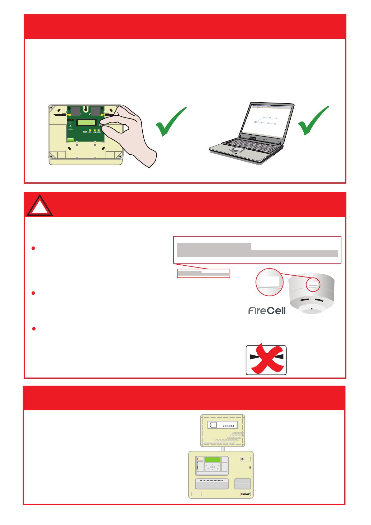
If your system has been supplied fully programmed, please be aware of the following
points:-
Step 1 Install the Panel & Hub:
!
FIRECELL PANEL - Loop 1 (68 Devices)
Address Name Type Zone Action Text
001.00 Call Point FireCell Call Point 01 Fire CP GF UNIT 1
001.00 Call Point FireCell Call Point 01 Fire CP GF UNIT 1
001.00 Call Point FireCell Call Point 01 Fire CP GF UNIT 1
001.00 Call Point FireCell Call Point 01 Fire CP GF UNIT 1
001.00 Call Point FireCell Call Point 01 Fire CP GF UNIT 1
001.00 Call Point FireCell Call Point 01 Fire CP GF UNIT 1
001.00 Call Point FireCell Call Point 01 Fire CP GF UNIT 1
001.00 Call Point FireCell Call Point 01 Fire CP GF UNIT 1
001.00 Call Point FireCell Call Point 01 Fire CP GF UNIT 1
001.00 Call Point FireCell Call Point 01 Fire CP GF UNIT 1
001.00 Call Point FireCell Call Point 01 Fire CP GF UNIT 1
001.00 Call Point FireCell Call Point 01 Fire CP GF UNIT 1
001.00 Call Point FireCell Call Point 01 Fire CP GF UNIT 1
001.00 Call Point FireCell Call Point 01 Fire CP GF UNIT 1
001.00 Call Point FireCell Call Point 01 Fire CP GF UNIT 1
001.00 Call Point FireCell Call Point 01 Fire CP GF UNIT 1
001.00 Call Point FireCell Call Point 01 Fire CP GF UNIT 1
001.00 Call Point FireCell Call Point 01 Fire CP GF UNIT 1
001.00 Call Point FireCell Call Point 01 Fire CP GF UNIT 1
001.00 Call Point FireCell Call Point 01 Fire CP GF UNIT 1
001.00 Call Point FireCell Call Point 01 Fire CP GF UNIT 1
001.00 Call Point FireCell Call Point 01 Fire CP GF UNIT 1
001.00 Call Point FireCell Call Point 01 Fire CP GF UNIT 1
001.00 Call Point FireCell Call Point 01 Fire CP GF UNIT 1
001.00 Call Point FireCell Call Point 01 Fire CP GF UNIT 1
001.00 Call Point FireCell Call Point 01 Fire CP GF UNIT 1
001.00 Call Point FireCell Call Point 01 Fire CP GF UNIT 1
001.00 Call Point FireCell Call Point 01 Fire CP GF UNIT 1
001.00 Call Point FireCell Call Point 01 Fire CP GF UNIT 1
001.00 Call Point FireCell Call Point 01 Fire CP GF UNIT 1
001.00 Call Point FireCell Call Point 01 Fire CP GF UNIT 1
001.00 Call Point FireCell Call Point 01 Fire CP GF UNIT 1
L1/036
A text address schedule will be
supplied with the Control Panel packaging
detailing device locations and address
numbers.
All products will be labelled with
their associated address numbers so must
be installed in their correct locations.
DO NOT press the device logon
buttons if the system is supplied this way.
Doing this will un-programme the device
from the system.
Radio Detector Base
Part No: FCX-170-001
EN54-25:2008
Technical Data see Installation guide
PRESS HERE TO
LOG ON
POWER
FAU LT
SYSTEM
FAU LT
FIRE
Fire Alarm Control
Radio Hub
Control Panel
If the site has been surveyed, the
location of the units will be indicated
on the survey report located within the
control panel packaging.
See FireCell Instruction Pack for more
information.
©2018 EMS Ltd. All rights reserved Page 2 of 4 MK140 Iss 6 15/08/2018 AJM


