DBI-SALA DBI-SALA® Reusable Heavy-Duty Roof Anchor 2103673, 1 EA Operating instructions
- Type
- Operating instructions

© 3M 2019
OSHA 1910.140 OSHA 1926.502
USER INSTRUCTION MANUAL
5902138 REv. G
Roof AnchoR &
Sayine
TM
Horizontal Lifeline System
1
7600511
A B c D
50 ft
(15 m)
9.1 in
(23.2 cm)
24 in
(61 cm)
3,600 lbs
(16 kN)
D
D
2103673
5.1 lbs (2.3 KG)
7600505
18 lbs (8.2 KG)
2103673
5.1 lbs (2.3 KG)
c
B
A
c
B
Page is loading ...
Page is loading ...
Page is loading ...
Page is loading ...

FORM NO: 5908299 REV: A
6
SAFETY INFORMATION
Please read, understand, and follow all safety information contained in these instructions prior to the use of this Anchorage Connector.
FAILURE TO DO SO COULD RESULT IN SERIOUS INJURY OR DEATH.
These instructions must be provided to the user of this equipment. Retain these instructions for future reference.
Intended Use:
This Anchorage Connector is intended for use as part of a complete personal fall protection system.
Use in any other application including, but not limited to, material handling, recreational or sports related activities, or other activities not described in
the User Instructions, is not approved by 3M and could result in serious injury or death.
This device is only to be used by trained users in workplace applications.
! WARNING
This Anchorage Connector is part of a personal fall protection system. It is expected that all users be fully trained in the safe installation and operation
of their personal fall protection system. Misuse of this device could result in serious injury or death. For proper selection, operation, installation,
maintenance, and service, refer to these User Instructions and all manufacturer recommendations, see your supervisor, or contact 3M Technical Service.
• To reduce the risks associated with working with an Anchorage Connector which, if not avoided, could result in serious injury or
death:
- Inspect the device before each use, at least annually, and after any fall event. Inspect in accordance with the User Instructions.
- If inspection reveals an unsafe or defective condition, remove the device from service and repair or replace according to the User Instructions.
- Any device that has been subject to fall arrest or impact force must be immediately removed from service and destroyed.
- The device must only be installed in the specied substrates or on structures detailed in the User Instructions. Installations and use outside the
scope of this instruction must be approved by 3M Fall Protection.
- The substrate or structure to which the anchorage connector is attached must be able to sustain the static loads specied for the anchor in the
orientations permitted in the User Instructions.
- Only connect other fall protection subsystems to the designated anchorage connection point on the device.
- Prior to drilling or fastening, ensure no electric lines, gas lines, or other critical embedded systems will be contacted by the drill or the device.
- Ensure that fall protection systems/subsystems assembled from components made by different manufacturers are compatible and meet the
requirements of applicable standards, including the ANSI Z359 or other applicable fall protection codes, standards, or requirements. Always
consult a Competent or Qualied Person before using these systems.
• To reduce the risks associated with working at height which, if not avoided, could result in serious injury or death:
- Ensure your health and physical condition allow you to safely withstand all of the forces associated with working at height. Consult with your
doctor if you have any questions regarding your ability to use this equipment.
- Never exceed allowable capacity of your fall protection equipment.
- Never exceed maximum free fall distance of your fall protection equipment.
- Do not use any fall protection equipment that fails pre-use or other scheduled inspections, or if you have concerns about the use or suitability
of the equipment for your application. Contact 3M Technical Services with any questions.
- Some subsystem and component combinations may interfere with the operation of this equipment. Only use compatible connections. Consult
3M prior to using this equipment in combination with components or subsystems other than those described in the User Instructions.
- Use extra precautions when working around moving machinery (e.g., top drive of oil rigs) electrical hazards, extreme temperatures, chemical
hazards, explosive or toxic gases, sharp edges, or below overhead materials that could fall onto you or your fall protection equipment.
- Use Arc Flash or Hot Works devices when working in high heat environments.
- Avoid surfaces and objects that can damage the user or equipment.
- Ensure there is adequate fall clearance when working at height.
- Never modify or alter your fall protection equipment. Only 3M or parties authorized, in writing, by 3M may make repairs to the equipment.
- Prior to use of fall protection equipment, ensure a rescue plan is in place which allows for prompt rescue if a fall incident occurs.
- If a fall incident occurs, immediately seek medical attention for the worker who has fallen.
- Do not use a body belt for fall arrest applications. Use only a Full Body Harness.
- Minimize swing falls by working as directly below the anchorage point as possible.
- If training with this device, a secondary fall protection system must be utilized in a manner that does not expose the trainee to an unintended
fall hazard.
- Always wear appropriate personal protective equipment when installing, using, or inspecting the device/system.
EN

7
SIT 5908279 Rev. B
SAFETY INFORMATION
Please read, understand, and follow all safety information contained in these instructions prior to the use of this Horizontal System.
FAILURE TO DO SO COULD RESULT IN SERIOUS INJURY OR DEATH.
These instructions must be provided to the user of this equipment. Retain these instructions for future reference.
Intended Use:
This Horizontal System is intended for use as part of a complete personal fall protection system.
Use in any other application including, but not limited to, material handling, recreational or sports related activities, or other activities not described in
the User Instructions, is not approved by 3M and could result in serious injury or death.
This system is only to be used by trained users in workplace applications.
! WARNING
This Horizontal System is part of a personal fall protection system. It is expected that all users be fully trained in the safe installation and operation of
their personal fall protection system. Misuse of this device could result in serious injury or death. For proper selection, operation, installation,
maintenance, and service, refer to these User Instructions and all manufacturer recommendations, see your supervisor, or contact 3M Technical Service
• To reduce the risks associated with working with a Horizontal System which, if not avoided, could result in serious injury or death:
- Inspect the system before each use, at least annually, and after any fall event. Inspect in accordance with the User Instructions.
- If inspection reveals an unsafe or defective condition, remove the system from service and repair or replace according to the User Instructions.
- Any system that has been subject to fall arrest or impact force must be immediately removed from service and all components must be
inspected by a Competent Person prior to being used again.
- Ensure system is appropriate for the number of simultaneous users.
- Work as closely to the horizontal lifeline as possible to prevent swing fall and limit fall clearance requirements. Refer to connecting device User
Instructions for more information.
- Ensure that fall protection systems/subsystems assembled from components made by different manufacturers are compatible and meet the
requirements of applicable standards, including the ANSI Z359 or other applicable fall protection codes, standards, or requirements. Always
consult a Competent or Qualied Person before using these systems.
• To reduce the risks associated with working at height which, if not avoided, could result in serious injury or death:
- Ensure your health and physical condition allow you to safely withstand all of the forces associated with working at height. Consult with your
doctor if you have any questions regarding your ability to use this equipment.
- Never exceed allowable capacity of your fall protection equipment.
- Never exceed maximum free fall distance of your fall protection equipment.
- Do not use any fall protection equipment that fails pre-use or other scheduled inspections, or if you have concerns about the use or suitability
of the equipment for your application. Contact 3M Technical Services with any questions.
- Some subsystem and component combinations may interfere with the operation of this equipment. Only use compatible connections. Consult
3M prior to using this equipment in combination with components or subsystems other than those described in the User Instructions.
- Use extra precautions when working around moving machinery (e.g. top drive of oil rigs) electrical hazards, extreme temperatures, chemical
hazards, explosive or toxic gases, sharp edges, or below overhead materials that could fall onto you or the fall protection equipment.
- Use Arc Flash or Hot Works devices when working in high heat environments.
- Avoid surfaces and objects that can damage the user or equipment.
- Ensure there is adequate fall clearance when working at height.
- Never modify or alter your fall protection equipment. Only 3M or parties authorized in writing by 3M may make repairs to the equipment.
- Prior to use of fall protection equipment, ensure a rescue plan is in place which allows for prompt rescue if a fall incident occurs.
- If a fall incident occurs, immediately seek medical attention for the fallen worker for the worker who has fallen.
- Do not use a body belt for fall arrest applications. Use only a Full Body Harness.
- Minimize swing falls by working as directly below the anchorage point as possible.
- If training with this device, a secondary fall protection system must be utilized in a manner that does not expose the trainee to an unintended
fall hazard.
- Always wear appropriate personal protective equipment when installing, using, or inspecting the device/system.
EN

8
;
Prior to installation and use of this equipment, record the product identication information from the ID label in the
Inspection and Maintenance Log (Table 2) at the back of this manual.
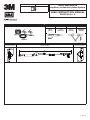
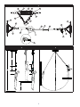
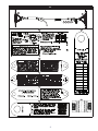
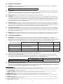
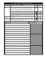
PRODUCT DESCRIPTION:
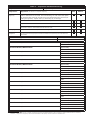
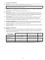
2103673: Figure 2 illustrates the 3M™ DBI-SALA™ Roof Anchor and Sayine Horizontal Lifeline System. The Roof Anchor (H)
consists of a cadmium plated forged O-ring (K), 9/32-inch alloy chain (G), and 3-inch wide rubber belt (D) attached to a steel
base. In use, the steel base (E) is attached to the roof structure per these instructions. The O-ring (K) is used for connection of
the fall arrest or restraint system.
7611904: Sayine Synthetic Horizontal Lifeline, 50 foot (15 m), includes two Roof Anchors. Equipped with product for single
user.
7611907: Equipped with product for two (2) users.
Table 1 – Specications
System Specications:
Capacity: This anchorage connector is designed for use by persons with a combined weight (person, clothing,
tools, etc.) of no more than 310 lbs (140 kg). Only one personal protective system may be connected
to the roof anchor (2103673) at any time. DBI/SALA Sayine Synthetic Horizontal Lifeline Systems
connected to the 2103673 roof anchor are rated for two users.
Anchorage: Fall Arrest: The structure to which the Anchorage Connector is attached must sustain static loads
applied in the directions permitted by the Fall Arrest System of at least: 3,600 lbs (16 kN) with
certication of a Qualied Person
2
; or 5,000 lbs (22 kN) without certication. When more than one
Personal Fall Arrest System (PFAS) is attached to an anchorage, these static loads must be multiplied by
the number of PFAS attached to the anchorage.
;
OSHA 1926.500 and OSHA 1910.66: Anchorages used for attachment to a Personal Fall Arrest
System (PFAS) must be independent of any anchorage used to suspend or support platforms and
must support 5,000 lbs (22 kN) per user attached, or be designed, installed, and used as part of a
completer PFAS which maintains a Safety Factor of a least 2 and is supervised by a Qualied Person
2
.
Restraint: The structure to which the Anchorage Connector is attached must sustain static loads
applied in the directions permitted by the Restraint System of at least 3,000 lbs (13 kN). When more
than one Restraint System is attached to an anchorage, the static load must be multiplied by the
number of Restraint Systems attached to the anchorage.
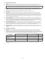
Dimensions: See Figure 1 for the dimensions of each Roof Anchor model.
Product Weight: See Figure 1 for the weight of each Roof Anchor model.
Standards: Meets the test requirements of OSHA 1910.140 and 1926.502
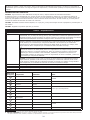
Component Specications:
Figure 2
Reference Component Materials Note:
A
Clamp Plate
Steel
Zinc Plated
B
Rivet
Steel
C
Labels
Scrimmed Vinyl
D
Belt
Rubber
E
Side Plate
Steel
Electro-deposition PaintF
Stud
Steel
G
Chain
Steel
H
Roof Anchor
NA
I
Horizontal Lifeline System
NA
J
Rope Direction
NA
K
O-Ring
Steel
Zinc Plated
L
Connector
Steel
M
Rope
Nylon
1 Capacity: 310 lbs (140 kg) is the capacity range required by ANSI.
2 Qualied Person: An individual with a recognized degree or professional certicate, and extensive experience in Fall Protection. This individual must be capable
of design, analysis, evaluation, and specication in Fall Protection.

9
1.0 PRODUCT APPLICATION
1.1 PURPOSE: Anchorage Connectors are designed to provide anchorage connection points for Fall Arrest
1
, Fall Restraint
2
,
Work Positioning
3
, or Rescue
4
systems.
;
Do not connect Lifting Equipment to the Anchorage Connector.
1.2 STANDARDS: Your Anchorage Connector conforms to the national or regional standard(s) identied on the front cover
of these instructions. If this product is resold outside the original country of destination, the re-seller must provide these
instructions in the language of the country in which the product will be used.
1.3 SUPERVISION: Use of this equipment must be supervised by a Competent Person
5
.
1.4 TRAINING: This equipment must be installed and used by persons trained in its correct application. This manual is to
be used as part of an employee training program as required by ANSI and OSHA, and/or regional regulations. It is the
responsibility of the users and installers of this equipment to ensure they are familiar with these instructions, trained in
the correct care and use of this equipment, and are aware of the operating characteristics, application limitations, and
consequences of improper use of this equipment.
1.5 RESCUE PLAN: When using this equipment and connecting subsystem(s), the employer must have a rescue plan and
the means at hand to implement and communicate that plan to users, authorized persons
6
, and rescuers
7
. A trained, on-
site rescue team is recommended. Team members should be provided with the equipment and techniques to perform a
successful rescue. Training should be provided on a periodic basis to ensure rescuer prociency.
1.6 INSPECTION FREQUENCY:
The Anchorage Connector shall be inspected by the user before each use and, additionally,
by a competent person other than the user at intervals of no longer than one year.
8
Inspection procedures are described in
the “Inspection and Maintenance Log”. Results of each Competent Person inspection should be recorded on copies of the
“Inspection and Maintenance Log”.
1.7 AFTER A FALL: If the Anchorage Connector is subjected to the forces of arresting a fall, it must be removed from service
immediately, clearly marked “DO NOT USE”, and then either destroyed or forwarded to 3M for replacement or repair.
2.0 SYSTEM REQUIREMENTS
2.1 ANCHORAGE: Anchorage structure requirements vary with the system application and whether it is a certied
anchorage
9
or non-certied anchorage
10
. The structure to which a fall arrest, restraint, positioning, or rescue system is
attached must sustain static loads applied in the directions permitted as shown in the following table. Anchorage Strength
requirements, along with system applications, are specied below, unless noted or dened otherwise in Table 1:
Fall Protection System Certied Anchorage
9
Non-Certied Anchorage
10
Dened by
Fall Arrest 2 times maximum arresting force 5,000 lbs (22.2 kN) OSHA, ANSI
Restraint/Travel Restraint 2 times foreseeable force
1,000 lbs (4.4 kN) per ANSI
5,000 lbs (22.2 kN) per OSHA
OSHA, ANSI
Work Positioning 2 times foreseeable force 3,000 lbs (13.3 kN) OSHA, ANSI
Rescue 5 times applied load 3,000 lbs (13.3 kN) ANSI
When more than one system is attached to an anchorage, the strengths stated above must be multiplied by the number
of systems attached to the anchorage. See ANSI Z359.2 for more information.
2.2 PERSONAL FALL ARREST SYSTEM: Figure 1 illustrates the application of this Anchorage Connector. Personal Fall
Arrest Systems (PFAS) used with the system must meet applicable Fall Protection standards, codes, and requirements.
The PFAS must incorporate a Full Body Harness and limit Arresting Force to the following values:
Maximum Arresting Force Free Fall
PFAS with Shock Absorbing Lanyard 1800 lbs (8 kN)
Refer to the instruction(s) included with your
Lanyard or SRD for Free Fall limitations.
PFAS with Self Retracting Device (SRD) 1800 lbs (8 kN)
2.3 FALL PATH AND SRD LOCKING SPEED: A clear path is required to assure positive locking of an SRD. Situations which
do not allow for an unobstructed fall path should be avoided. Working in confined or cramped spaces may not allow the
body to reach sufficient speed to cause the SRD to lock if a fall occurs. Working on slowly shifting material, such as sand
or grain, may not allow enough speed buildup to cause the SRD to lock.
1 Fall Arrest System: A collection of Fall Protection Equipment congured to arrest a free fall. Protects the user in the event of a fall. Free fall is permitted up to
the limits allowed by the connecting device (either an Energy Absorbing Lanyard or Self-Retracting Device (SRD)).
2 Restraint System: A collection of Fall Protection Equipment congured to prevent the person’s center of gravity from reaching a fall hazard.Prevents the user
from reaching a hazard. No vertical free fall is permitted.
5 Competent Person: One who is capable of identifying existing and predictable hazards in the surroundings or working conditions which are unsanitary,
hazardous, or dangerous to employees, and who has authorization to take prompt corrective measures to eliminate them.
6 Authorized Person: A person assigned by the employer to perform duties at a location where the person will be exposed to a fall hazard.
7 Rescuer: Person or persons other than the rescue subject acting to perform an assisted rescue by operation of a rescue system.
8 Inspection Frequency: Extreme working conditions (harsh environments, prolonged use, etc.) may require increasing the frequency of competent person
inspections.
9 Certied Anchorage: An anchorage for fall arrest, positioning, restraint, or rescue systems that a Qualied Person certies to be capable of meeting the
criteria for a certied anchorage according to Section 2.1.
10 Non-Certied Anchorage: A fall arrest anchorage that a Competent Person can judge to be capable of supporting the predetermined anchorage forces
listed in Section 2.1.

10
2.4 HAZARDS: Use of this equipment in areas with environmental hazards may require additional precautions to prevent
injury to the user or damage to the equipment. Hazards may include, but are not limited to: heat, chemicals, corrosive
environments, high voltage power lines, explosive or toxic gases, moving machinery, sharp edges, or overhead materials
that may fall and contact the user or Personal Fall Arrest System.
2.5 FALL CLEARANCE: Figure 3 illustrates the components of a Fall Arrest. There must be sufcient Fall Clearance (FC)
to arrest a fall before the user strikes the ground or other obstruction. Clearance is affected by a number of factors
including: Anchorage Location, (A) Lanyard Length, (B) Lanyard Deceleration Distance or SRD Maximum Arrest Distance,
(C) Harness Stretch and D-Ring/Connector Length and Settling. Refer to the instructions included with your Fall Arrest
subsystem for specics regarding Fall Clearance calculation.
2.6 SWING FALLS: Swing Falls occur when the anchorage point is not directly above the point where a fall occurs (see Figure
4). The force of striking an object in a swing fall may cause serious injury or death. Minimize swing falls by working as directly
below the anchorage point as possible. Do not permit a swing fall if injury could occur. Swing falls will signicantly increase the
clearance required when a Self-Retracting Device or other variable length connecting subsystem is used.
2.7 COMPONENT COMPATIBILITY: 3M equipment is designed for use with 3M approved components and subsystems
only. Substitutions or replacements made with non-approved components or subsystems may jeopardize compatibility of
equipment and may affect the safety and reliability of the complete system.
2.8 CONNECTOR COMPATIBILITY: Connectors are considered to be compatible with connecting elements when they
have been designed to work together in such a way that their sizes and shapes do not cause their gate mechanisms to
inadvertently open regardless of how they become oriented. Contact 3M if you have any questions about compatibility.
Connectors (hooks, carabiners, and D-rings) must be capable of supporting at least 5,000 lbs. (22.2 kN). Connectors
must be compatible with the anchorage or other system components. Do not use equipment that is not compatible.
Non-compatible connectors may unintentionally disengage (see Figure 5). Connectors must be compatible in size, shape,
and strength. If the connecting element to which a snap hook or carabiner attaches is undersized or irregular in shape, a
situation could occur where the connecting element applies a force to the gate of the snap hook or carabiner (A). This force
may cause the gate to open (B), allowing the snap hook or carabiner to disengage from the connecting point (C).
Self-locking snap hooks and carabiners are required by ANSI Z359 and OSHA.
2.9 MAKING CONNECTIONS: Snap hooks and carabiners used with this equipment must be self-locking. Ensure all
connections are compatible in size, shape and strength. Do not use equipment that is not compatible. Ensure all
connectors are fully closed and locked.
3M connectors (snap hooks and carabiners) are designed to be used only as specied in each product’s user’s instructions.
See Figure 6 for examples of inappropriate connections. Do not connect snap hooks and carabiners:
A. To a D-ring to which another connector is attached.
B. In a manner that would result in a load on the gate. Large throat snap hooks should not be connected to standard
size D-rings or similar objects which will result in a load on the gate if the hook or D-ring twists or rotates, unless the
snap hook complies is equipped with a 3,600 lb (16 kN) gate. Check the marking on your snap hook to verify that it
is appropriate for your application.
C. In a false engagement, where features that protrude from the snap hook or carabiner catch on the anchor, and
without visual conrmation seems to be fully engaged to the anchor point.
D. To each other.
E. Directly to webbing or rope lanyard or tie-back (unless the manufacturer’s instructions for both the lanyard and
connector specically allows such a connection).
F. To any object which is shaped or dimensioned such that the snap hook or carabiner will not close and lock, or that
roll-out could occur.
G. In a manner that does not allow the connector to align properly while under load.

11
3.0 INSTALLATION
;
Installation of the DBI-SALA Roof Anchor must be supervised by a Qualied Person
1
. The installation must be
certied by a Competent Person
2
as meeting the criteria for a Certied Anchorage, or that it is capable of supporting
the potential forces that could be encountered during a fall.
1
2
3.1 PLANNING: Plan your fall protection system prior to installation of the Roof Anchor. Account for all factors that may
affect your safety before, during and after a fall. Consider all requirements, limitations and specications dened in
Section 2 and Table 1.
3.2 INSTALLATION REQUIREMENTS
A. ROOF ANCHOR SITE PLAN: Before starting the roof construction, a site plan should establish where the roof anchors
will be installed and when, during the construction process, they may be used. The following are guidelines on locating
roof anchors:
The roof anchor should be located at the roof peak (when possible) and at least 6 feet (1.8 m) from any exposed roof
edge. On very small roof areas, locate the roof anchor as far from the roof edge as possible.
Do not install roof anchors on unsupported roof structure such as eve or gable overhangs.
Do not install roof anchors on facia boards.
Roof anchors should be installed at 8 foot (2.4 m) spacing along the roof peak.
Hip roofs require a roof anchor on each hip face.
On long low pitched roofs, multiple roof anchors should be installed along gable ends (6 feet [1.8 m] from the edge)
to reduce swing fall hazards.
Figure 8 shows typical roof anchor locations for various roof congurations.
B. ROOF FRAMING: Roof framing members to which the roof anchors are attached must be in good condition. Members
must be free of splits, cracks, large knots or other defects that may weaken the member. Do not attach the roof
anchor to rotted or deteriorated wood.
;
Roof anchors installed onto a rafter or truss which previously had a roof anchor nailed or screwed in place must be
positioned to assure the new nails will not use any of the existing holes.
C. ROOF ANCHOR INSTALLATION: Roof anchors must be located on the roof in accordance with the previously
discussed site plan. Site work rules must be followed regarding when an installed anchor is ready for use (i.e. properly
braced, etc.).
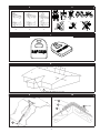
D. ATTACHING THE ROOF ANCHOR:
Figure 9:
Adjust the side plates to match the surface it will be mounted on, either a roof peak or a at surface. Position the
anchor on the roof so the 6 screw holes along the center of the side plates are over a roof (framing) member (A) (2x4
minimum).
Figure 10:
Then, push down to minimize any gap between the anchor (A) and the sheathing (B) and install twelve 16d nails or 6
lag screws (C) (3/16-inch or smaller pilot holes may be drilled for easier installation of lag screws). Use only 1/4-inch
x 2 1/2-inch or longer lag screws. See section 5.0 for pre-use inspection.
;
The lag screws or nails must go through the sheathing (Figure 10B) and into the roof member. If they do not, the
anchor will not hold the rated loads and serious injury or death could occur.
;
Use only 16d nails or 1/4-inch x 2 1/2-inch or longer lag screws.
;
If the 2103673 is installed over old shingles, make sure it is nailed or screwed into the roof member (Figure 10D
rafter or truss).
E. REMOVAL OF ROOF ANCHOR: Remove the 2103673 roof anchor prior to shingling the area with the anchor. To
remove it, unscrew the lag screws or pull the nails and remove. The 2103673 is a removable roof anchor and is
designed to be reinstalled following inspection per section 5.0.
3.3 CONNECTING TO ROOF ANCHOR: Consider all requirements, limitations and specications dened in Section 2.9
Making Connections. Connection to the installed roof anchor may be made using a self locking snap hook or self
locking and self closing carabiner only. Do not use a knot to connect a lifeline to the roof anchor. Do not pass a lanyard or
lifeline through the roof anchor ring and hook back into lanyard or lifeline. When connecting, make sure connections are
fully closed and locked.
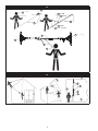
Figure 11 illustrates proper connection of typical fall arrest or restraint equipment to the roof anchor:
A: Full Body Harness B: Self Retracting Lifeline C: Rope Grab D: Lifeline E: Roof Anchor F: Lanyard G: Energy Absorber
H: Synthetic HLL System
When using an energy absorbing lanyard (F), connect the energy absorber “pack” (G) end to the harness. When using a
self retracting lifeline (B), make sure the device is properly positioned so that retraction is not hindered. Always protect
the lifeline/lanyard from abrading against sharp or abrasive surfaces on the roof. Make sure all connections are compatible
is size, shape and strength. Never connect more than one personal protective system to any single roof anchor at a time.

12
3.4 CAPTIVATING LIFELINE: It is acceptable to captivate a lifeline (i.e. rope grab system) to an anchorage close to the
work area with a carabiner, see Figure 12:
A: Roof Peak B: Roof Edge C: Lifeline D: Roof Anchor E: Carabiner F: Rope Grab
;
Do not captivate the lifeline of a self retracting lifeline as this may affect the performance of its internal braking.
;
Read and follow manufacturer’s instructions for associated equipment (i.e. full body harness, shock absorbing
lanyard, self retracting lifeline, etc.) used in your personal fall arrest system.
;
For special (custom) versions of this product, follow the instructions herein. If enclosed, see attached supplement
for additional instructions to be followed when using a customized product.
4.0 USE
;
Training must be conducted without exposing the trainee to a fall hazard. Training should be repeated on a periodic
basis.
4.1 BEFORE EACH USE: Verify that your work area and Personal Fall Arrest System (PFAS) meet all criteria dened in
Section 2 and a formal Rescue Plan is in place. Inspect the Roof Anchor per the ‘User’ inspection points dened on the
“Inspection and Maintenance Log” (Table 2). If inspection reveals an unsafe or defective condition, do not use the system.
Remove the system from service and destroy, or contact 3M regarding replacement or repair.
4.2 FALL ARREST CONNECTIONS: The Roof Anchor is used with a Full Body Harness and Energy Absorbing Lanyard or Self-
Retracting Device (SRD). Figure 10 illustrates connection of the Lanyard or SRD between the Harness and Roof Anchor.
Connect the Lanyard or SRD between the D-Ring on the Roof Anchor and the back Dorsal D-Ring on the Harness as
instructed in the instructions included with the Lanyard or SRD.
;
Horizontal Lifeline Connections: See the product instruction for your Horizontal Lifeline (HLL) for proper
connection of the Lanyard or SRD to the HLL.
5.0 INSPECTION
5.1 INSPECTION FREQUENCY: The Roof Anchor must be inspected at the intervals dened in Section 1. Inspection
procedures are described in the “Inspection and Maintenance Log” (Table 2). Inspect all other components of the Fall
Protection System per the frequencies and procedures dened in the manufacturer’s instructions.
;
Roof Anchors are equipped with a Radio Frequency Identication (RFID) Tag (Figure 7). The RFID Tag can be used
in conjunction with a Handheld Reading Device to simplify inspection and inventory control and provide records for your
fall protection equipment.
5.2 DEFECTS: If inspection reveals an unsafe or defective condition, remove the Roof Anchor from service immediately and
contact 3M regarding replacement or repair. Do not attempt to repair the Fall Arrest System.
;
Authorized Repairs Only: Only 3M or parties authorized in writing my make repairs to this equipment.
5.3 PRODUCT LIFE: The functional life of the Fall Arrest System is determined by work conditions and maintenance. As long
as the product passes inspection criteria, it may remain in service.
6.0 MAINTENANCE, SERVICING, STORAGE
6.1 CLEANING: Periodically clean the Roof Anchor’s metal components with a soft brush, warm water, and a mild soap
solution. Ensure parts are thoroughly rinsed with clean water.
6.2 SERVICE: Only 3M or parties authorized in writing by 3M may make repairs to this equipment. If the Roof Anchor has
been subject to fall force or inspection reveals an unsafe or defective conditions, remove the system from service and
contact 3M regarding replacement or repair.
6.3 STORAGE AND TRANSPORT: When not in use, store and transport the Roof Anchor and associated fall protection
equipment in a cool, dry, clean environment out of direct sunlight. Avoid areas where chemical vapors may exist.
Thoroughly inspect components after extended storage.
7.0 LABELS
Figure 13 illustrates labels on the Roof Anchor and Sayine Horizontal Lifeline System. Labels must be replaced if they are not
fully legible.

Table 2 – Inspection and Maintenance Log
Inspection Date: Inspected By:
Components: Inspection: (See Section 1 for Inspection Frequency) User
Competent
Person
1
Roof Anchor
(Figure 2)
Inspect the Roof Anchor for physical damage. Look carefully for any signs of cracks,
dents or deformities in the metal. Check for bending, the roof anchor side plates
(E) should be at. Rivets (B) should be securely attached and fully clinched (not
pulling through hole). Inspect chain (G) and O-Ring (K) for damage.
Ensure the Roof Anchor is still securely attached. If loose, do not use.
Inspect the entire unit for corrosion.
Ensure the condition of the roof will support the Roof Anchor loads, see section 2.1. An anchor
connected to rotted or deteriorated wood should not be used.
Labels (Figure 13)
Verify that all labels are securely attached and are legible (see ‘Labels’)
PFAS and Other
Equipment
Additional Personal Fall Arrest System (PFAS) equipment (harness, SRL, etc) that are used with
the Flexiguard Anchorage System should be installed and inspected per the manufacturer’s
instructions.
Serial Number(s): Date Purchased:
Model Number: Date of First Use:
Corrective Action/Maintenance: Approved By:
Date:
Corrective Action/Maintenance: Approved By:
Date:
Corrective Action/Maintenance: Approved By:
Date:
Corrective Action/Maintenance: Approved By:
Date:
Corrective Action/Maintenance: Approved By:
Date:
Corrective Action/Maintenance: Approved By:
Date:
Corrective Action/Maintenance: Approved By:
Date:
Corrective Action/Maintenance: Approved By:
Date:
Corrective Action/Maintenance: Approved By:
Date:
Corrective Action/Maintenance: Approved By:
Date:
Corrective Action/Maintenance: Approved By:
Date:
Corrective Action/Maintenance: Approved By:
Date:
Corrective Action/Maintenance: Approved By:
Date:
Corrective Action/Maintenance: Approved By:
Date:
Corrective Action/Maintenance: Approved By:
Date:
Corrective Action/Maintenance: Approved By:
Date:
1 Competent Person: One who is capable of identifying existing and predictable hazards in the surroundings or working conditions which are unsanitary,
hazardous, or dangerous to employees, and who has authorization to take prompt corrective measures to eliminate them.
Page is loading ...
Page is loading ...

16
;
Prior to installation and use of this equipment, record the product identication information from the ID label in the
Inspection and Maintenance Log (Table 2) at the back of this manual.
PRODUCT DESCRIPTION:
2103673: Figure 2 illustrates the 3M™ DBI-SALA™ Roof Anchor and Sayine Horizontal Lifeline System. The Roof Anchor (H)
consists of a cadmium plated forged O-ring (K), 9/32-inch alloy chain (G), and 3-inch wide rubber belt (D) attached to a steel
base. In use, the steel base (E) is attached to the roof structure per these instructions. The O-ring (K) is used for connection of
the fall arrest or restraint system.
7611904: Sayine Synthetic Horizontal Lifeline, 50 foot (15 m), includes two Roof Anchors. Equipped with product for single
user.
7611907: Equipped with product for two (2) users.
Table 1 – Specications
System Specications:
Capacity: This anchorage connector is designed for use by persons with a combined weight (person, clothing,
tools, etc.) of no more than 310 lbs (140 kg). Only one personal protective system may be connected
to the roof anchor (2103673) at any time. DBI/SALA Sayine Synthetic Horizontal Lifeline Systems
connected to the 2103673 roof anchor are rated for two users.
Anchorage: Fall Arrest: The structure to which the Anchorage Connector is attached must sustain static loads
applied in the directions permitted by the Fall Arrest System of at least: 3,600 lbs (16 kN) with
certication of a Qualied Person
2
; or 5,000 lbs (22 kN) without certication. When more than one
Personal Fall Arrest System (PFAS) is attached to an anchorage, these static loads must be multiplied by
the number of PFAS attached to the anchorage.
;
OSHA 1926.500 and OSHA 1910.66: Anchorages used for attachment to a Personal Fall Arrest
System (PFAS) must be independent of any anchorage used to suspend or support platforms and
must support 5,000 lbs (22 kN) per user attached, or be designed, installed, and used as part of a
completer PFAS which maintains a Safety Factor of a least 2 and is supervised by a Qualied Person
2
.
Restraint: The structure to which the Anchorage Connector is attached must sustain static loads
applied in the directions permitted by the Restraint System of at least 3,000 lbs (13 kN). When more
than one Restraint System is attached to an anchorage, the static load must be multiplied by the
number of Restraint Systems attached to the anchorage.
Dimensions: See Figure 1 for the dimensions of each Roof Anchor model.
Product Weight: See Figure 1 for the weight of each Roof Anchor model.
Standards: Meets the test requirements of OSHA 1910.140 and 1926.502
Component Specications:
Figure 2
Reference Component Materials Note:
A
Clamp Plate
Steel
Zinc Plated
B
Rivet
Steel
C
Labels
Scrimmed Vinyl
D
Belt
Rubber
E
Side Plate
Steel
Electro-deposition PaintF
Stud
Steel
G
Chain
Steel
H
Roof Anchor
NA
I
Horizontal Lifeline System
NA
J
Rope Direction
NA
K
O-Ring
Steel
Zinc Plated
L
Connector
Steel
M
Rope
Nylon
1 Capacity: 310 lbs (140 kg) is the capacity range required by ANSI.
2 Qualied Person: An individual with a recognized degree or professional certicate, and extensive experience in Fall Protection. This individual must be capable
of design, analysis, evaluation, and specication in Fall Protection.
Page is loading ...
Page is loading ...

19
3.0 INSTALLATION
;
Installation of the DBI-SALA Roof Anchor must be supervised by a Qualied Person
1
. The installation must be
certied by a Competent Person
2
as meeting the criteria for a Certied Anchorage, or that it is capable of supporting
the potential forces that could be encountered during a fall.
1
2
3.1 PLANNING: Plan your fall protection system prior to installation of the Roof Anchor. Account for all factors that may
affect your safety before, during and after a fall. Consider all requirements, limitations and specications dened in
Section 2 and Table 1.
3.2 INSTALLATION REQUIREMENTS
A. ROOF ANCHOR SITE PLAN: Before starting the roof construction, a site plan should establish where the roof anchors
will be installed and when, during the construction process, they may be used. The following are guidelines on locating
roof anchors:
The roof anchor should be located at the roof peak (when possible) and at least 6 feet (1.8 m) from any exposed roof
edge. On very small roof areas, locate the roof anchor as far from the roof edge as possible.
Do not install roof anchors on unsupported roof structure such as eve or gable overhangs.
Do not install roof anchors on facia boards.
Roof anchors should be installed at 8 foot (2.4 m) spacing along the roof peak.
Hip roofs require a roof anchor on each hip face.
On long low pitched roofs, multiple roof anchors should be installed along gable ends (6 feet [1.8 m] from the edge)
to reduce swing fall hazards.
Figure 8 shows typical roof anchor locations for various roof congurations.
B. ROOF FRAMING: Roof framing members to which the roof anchors are attached must be in good condition. Members
must be free of splits, cracks, large knots or other defects that may weaken the member. Do not attach the roof
anchor to rotted or deteriorated wood.
;
Roof anchors installed onto a rafter or truss which previously had a roof anchor nailed or screwed in place must be
positioned to assure the new nails will not use any of the existing holes.
C. ROOF ANCHOR INSTALLATION: Roof anchors must be located on the roof in accordance with the previously
discussed site plan. Site work rules must be followed regarding when an installed anchor is ready for use (i.e. properly
braced, etc.).
D. ATTACHING THE ROOF ANCHOR:
Figure 9:
Adjust the side plates to match the surface it will be mounted on, either a roof peak or a at surface. Position the
anchor on the roof so the 6 screw holes along the center of the side plates are over a roof (framing) member (A) (2x4
minimum).
Figure 10:
Then, push down to minimize any gap between the anchor (A) and the sheathing (B) and install twelve 16d nails or 6
lag screws (C) (3/16-inch or smaller pilot holes may be drilled for easier installation of lag screws). Use only 1/4-inch
x 2 1/2-inch or longer lag screws. See section 5.0 for pre-use inspection.
;
The lag screws or nails must go through the sheathing (Figure 10B) and into the roof member. If they do not, the
anchor will not hold the rated loads and serious injury or death could occur.
;
Use only 16d nails or 1/4-inch x 2 1/2-inch or longer lag screws.
;
If the 2103673 is installed over old shingles, make sure it is nailed or screwed into the roof member (Figure 10D
rafter or truss).
E. REMOVAL OF ROOF ANCHOR: Remove the 2103673 roof anchor prior to shingling the area with the anchor. To
remove it, unscrew the lag screws or pull the nails and remove. The 2103673 is a removable roof anchor and is
designed to be reinstalled following inspection per section 5.0.
3.3 CONNECTING TO ROOF ANCHOR: Consider all requirements, limitations and specications dened in Section 2.9
Making Connections. Connection to the installed roof anchor may be made using a self locking snap hook or self
locking and self closing carabiner only. Do not use a knot to connect a lifeline to the roof anchor. Do not pass a lanyard or
lifeline through the roof anchor ring and hook back into lanyard or lifeline. When connecting, make sure connections are
fully closed and locked.
Figure 11 illustrates proper connection of typical fall arrest or restraint equipment to the roof anchor:
A: Full Body Harness B: Self Retracting Lifeline C: Rope Grab D: Lifeline E: Roof Anchor F: Lanyard G: Energy Absorber
H: Synthetic HLL System
When using an energy absorbing lanyard (F), connect the energy absorber “pack” (G) end to the harness. When using a
self retracting lifeline (B), make sure the device is properly positioned so that retraction is not hindered. Always protect
the lifeline/lanyard from abrading against sharp or abrasive surfaces on the roof. Make sure all connections are compatible
is size, shape and strength. Never connect more than one personal protective system to any single roof anchor at a time.

20
3.4 CAPTIVATING LIFELINE: It is acceptable to captivate a lifeline (i.e. rope grab system) to an anchorage close to the
work area with a carabiner, see Figure 12:
A: Roof Peak B: Roof Edge C: Lifeline D: Roof Anchor E: Carabiner F: Rope Grab
;
Do not captivate the lifeline of a self retracting lifeline as this may affect the performance of its internal braking.
;
Read and follow manufacturer’s instructions for associated equipment (i.e. full body harness, shock absorbing
lanyard, self retracting lifeline, etc.) used in your personal fall arrest system.
;
For special (custom) versions of this product, follow the instructions herein. If enclosed, see attached supplement
for additional instructions to be followed when using a customized product.
4.0 USE
;
Training must be conducted without exposing the trainee to a fall hazard. Training should be repeated on a periodic
basis.
4.1 BEFORE EACH USE: Verify that your work area and Personal Fall Arrest System (PFAS) meet all criteria dened in
Section 2 and a formal Rescue Plan is in place. Inspect the Roof Anchor per the ‘User’ inspection points dened on the
“Inspection and Maintenance Log” (Table 2). If inspection reveals an unsafe or defective condition, do not use the system.
Remove the system from service and destroy, or contact 3M regarding replacement or repair.
4.2 FALL ARREST CONNECTIONS: The Roof Anchor is used with a Full Body Harness and Energy Absorbing Lanyard or Self-
Retracting Device (SRD). Figure 10 illustrates connection of the Lanyard or SRD between the Harness and Roof Anchor.
Connect the Lanyard or SRD between the D-Ring on the Roof Anchor and the back Dorsal D-Ring on the Harness as
instructed in the instructions included with the Lanyard or SRD.
;
Horizontal Lifeline Connections: See the product instruction for your Horizontal Lifeline (HLL) for proper
connection of the Lanyard or SRD to the HLL.
5.0 INSPECTION
5.1 INSPECTION FREQUENCY: The Roof Anchor must be inspected at the intervals dened in Section 1. Inspection
procedures are described in the “Inspection and Maintenance Log” (Table 2). Inspect all other components of the Fall
Protection System per the frequencies and procedures dened in the manufacturer’s instructions.
;
Roof Anchors are equipped with a Radio Frequency Identication (RFID) Tag (Figure 7). The RFID Tag can be used
in conjunction with a Handheld Reading Device to simplify inspection and inventory control and provide records for your
fall protection equipment.
5.2 DEFECTS: If inspection reveals an unsafe or defective condition, remove the Roof Anchor from service immediately and
contact 3M regarding replacement or repair. Do not attempt to repair the Fall Arrest System.
;
Authorized Repairs Only: Only 3M or parties authorized in writing my make repairs to this equipment.
5.3 PRODUCT LIFE: The functional life of the Fall Arrest System is determined by work conditions and maintenance. As long
as the product passes inspection criteria, it may remain in service.
6.0 MAINTENANCE, SERVICING, STORAGE
6.1 CLEANING: Periodically clean the Roof Anchor’s metal components with a soft brush, warm water, and a mild soap
solution. Ensure parts are thoroughly rinsed with clean water.
6.2 SERVICE: Only 3M or parties authorized in writing by 3M may make repairs to this equipment. If the Roof Anchor has
been subject to fall force or inspection reveals an unsafe or defective conditions, remove the system from service and
contact 3M regarding replacement or repair.
6.3 STORAGE AND TRANSPORT: When not in use, store and transport the Roof Anchor and associated fall protection
equipment in a cool, dry, clean environment out of direct sunlight. Avoid areas where chemical vapors may exist.
Thoroughly inspect components after extended storage.
7.0 LABELS
Figure 13 illustrates labels on the Roof Anchor and Sayine Horizontal Lifeline System. Labels must be replaced if they are not
fully legible.

Table 2 – Inspection and Maintenance Log
Inspection Date: Inspected By:
Components: Inspection: (See Section 1 for Inspection Frequency) User
Competent
Person
1
Roof Anchor
(Figure 2)
Inspect the Roof Anchor for physical damage. Look carefully for any signs of cracks,
dents or deformities in the metal. Check for bending, the roof anchor side plates
(E) should be at. Rivets (B) should be securely attached and fully clinched (not
pulling through hole). Inspect chain (G) and O-Ring (K) for damage.
Ensure the Roof Anchor is still securely attached. If loose, do not use.
Inspect the entire unit for corrosion.
Ensure the condition of the roof will support the Roof Anchor loads, see section 2.1. An anchor
connected to rotted or deteriorated wood should not be used.
Labels (Figure 13)
Verify that all labels are securely attached and are legible (see ‘Labels’)
PFAS and Other
Equipment
Additional Personal Fall Arrest System (PFAS) equipment (harness, SRL, etc) that are used with
the Flexiguard Anchorage System should be installed and inspected per the manufacturer’s
instructions.
Serial Number(s): Date Purchased:
Model Number: Date of First Use:
Corrective Action/Maintenance: Approved By:
Date:
Corrective Action/Maintenance: Approved By:
Date:
Corrective Action/Maintenance: Approved By:
Date:
Corrective Action/Maintenance: Approved By:
Date:
Corrective Action/Maintenance: Approved By:
Date:
Corrective Action/Maintenance: Approved By:
Date:
Corrective Action/Maintenance: Approved By:
Date:
Corrective Action/Maintenance: Approved By:
Date:
Corrective Action/Maintenance: Approved By:
Date:
Corrective Action/Maintenance: Approved By:
Date:
Corrective Action/Maintenance: Approved By:
Date:
Corrective Action/Maintenance: Approved By:
Date:
Corrective Action/Maintenance: Approved By:
Date:
Corrective Action/Maintenance: Approved By:
Date:
Corrective Action/Maintenance: Approved By:
Date:
Corrective Action/Maintenance: Approved By:
Date:
1 Competent Person: One who is capable of identifying existing and predictable hazards in the surroundings or working conditions which are unsanitary,
hazardous, or dangerous to employees, and who has authorization to take prompt corrective measures to eliminate them.
Page is loading ...
Page is loading ...
Page is loading ...
Page is loading ...
Page is loading ...
Page is loading ...
Page is loading ...
Page is loading ...
Page is loading ...
Page is loading ...

USA
3833 SALA Way
Red Wing, MN 55066-5005
Toll Free: 800.328.6146
Phone: 651.388.8282
Fax: 651.388.5065
Brazil
Rua Anne Frank, 2621
Boqueirão Curitiba PR
81650-020
Brazil
Phone: 0800-942-2300
Mexico
Calle Norte 35, 895-E
Col. Industrial Vallejo
C.P. 02300 Azcapotzalco
Mexico D.F.
Phone: (55) 57194820
Colombia
Compañía Latinoamericana de Seguridad S.A.S.
Carrera 106 #15-25 Interior 105 Manzana 15
Zona Franca - Bogotá, Colombia
Phone: 57 1 6014777
Canada
260 Export Boulevard
Mississauga, ON L5S 1Y9
Phone: 905.795.9333
Toll-Free: 800.387.7484
Fax: 888.387.7484
EMEA (Europe, Middle East, Africa)
EMEA Headquarters:
Le Broc Center
Z.I. 1re Avenue - BP15
06511 Carros Le Broc Cedex
France
Phone: + 33 04 97 10 00 10
Fax: + 33 04 93 08 79 70
Australia & New Zealand
137 McCredie Road
Guildford
Sydney NSW 2161
Australia
Phone: +(61) 2 8753 7600
Toll-Free : 1800 245 002 (AUS)
Toll-Free : 0800 212 505 (NZ)
Fax: +(61) 2 8753 7603
Asia
Singapore:
1 Yishun Avenue 7
Singapore 768923
Phone: +65-6450 8888
Fax: +65-6552 2113
China:
38/F, Maxdo Center, 8 Xing Yi Rd
Shanghai 200336, P R China
Phone: +86 21 62753535
Fax: +86 21 52906521
Korea:
3M Koread Ltd
20F, 82, Uisadang-daero,
Yeongdeungpo-gu, Seoul
Phone: +82-80-033-4114
Fax: +82-2-3771-4271
Japan:
3M Japan Ltd
6-7-29, Kitashinagawa, Shinagawa-ku, Tokyo
Phone: +81-570-011-321
Fax: +81-3-6409-5818
WEBSITE:
3M.com/FallProtection
ISO
9001
FM534873
EU DECLARATION OF CONFORMITY:
3M.com/FallProtection/DOC
U.S. PRODUCT WARRANTY, LIMITED REMEDY
AND LIMITATION OF LIABILITY
WARRANTY: THE FOLLOWING IS MADE IN LIEU OF ALL WARRANTIES OR CONDITIONS, EXPRESS
OR IMPLIED, INCLUDING THE IMPLIED WARRANTIES OR CONDITIONS OF MERCHANTABILITY OR
FITNESS FOR A PARTICULAR PURPOSE.
Unless otherwise provided by applicable law, 3M fall protection products are warranted against factory
defects in workmanship and materials for a period of one year from the date of installation or fi rst use
by the original owner.
LIMITED REMEDY: Upon written notice to 3M, 3M will repair or replace any product determined by
3M to have a factory defect in workmanship or materials. 3M reserves the right to require product be
returned to its facility for evaluation of warranty claims. This warranty does not cover product damage
due to wear, abuse, misuse, damage in transit, failure to maintain the product or other damage beyond
3M’s control. 3M will be the sole judge of product condition and warranty options.
This warranty applies only to the original purchaser and is the only warranty applicable to 3M’s fall
protection products. Please contact 3M’s customer service department at 800-328-6146 or via email at
[email protected] for assistance.
LIMITATION OF LIABILITY: TO THE EXTENT PERMITTED BY APPLICABLE LAW, 3M IS NOT
LIABLE FOR ANY INDIRECT, INCIDENTAL, SPECIAL OR CONSEQUENTIAL DAMAGES INCLUDING,
BUT NOT LIMITED TO LOSS OF PROFITS, IN ANY WAY RELATED TO THE PRODUCTS REGARDLESS
OF THE LEGAL THEORY ASSERTED.
GARANTÍA GLOBAL DEL PRODUCTO, REPARACIONES LIMITADAS
Y LIMITACIÓN DE RESPONSABILIDAD
GARANTÍA: EL SIGUIENTE TEXTO SIRVE A MODO DE GARANTÍA O CONDICIÓN, EXPLÍCITA O IMPLÍCITA,
E INCLUYE LAS GARANTÍAS O CONDICIONES IMPLÍCITAS DE COMERCIABILIDAD O APTITUD PARA UN
PROPÓSITO ESPECÍFICO.
A menos que las leyes locales indiquen lo contrario, los productos de protección contra caídas 3M tienen
garantía por defectos de fábrica en la mano de obra y en los materiales durante un período de un año desde
la fecha de instalación o desde el primer uso del propietario original.
REPARACIONES LIMITADAS: 3M reparará o reemplazará un producto si determina que tiene un defecto
de fábrica en la mano de obra o en los materiales y tras haber recibido una notifi cación por escrito sobre
el presunto defecto. 3M se reserva el derecho de exigir la devolución del producto a sus instalaciones
para evaluar los reclamos sobre la calidad. Esta garantía no cubre los daños ocasionados por el desgaste,
el abuso, el mal mantenimiento, o como consecuencia del traslado del producto, u otros daños ajenos al
control de 3M. 3M será el único capaz de determinar la condición del producto y las opciones de la garantía.
Esta garantía solo se aplica al comprador original y es la única garantía válida para los productos de
protección contra caídas 3M. Comuníquese con el departamento de servicio al cliente de 3M de su región
para obtener ayuda.
LIMITACIÓN DE RESPONSABILIDAD: EN LA MEDIDA PERMITIDA POR LAS LEYES LOCALES, 3M NO
SERÁ RESPONSABLE DE LOS DAÑOS INDIRECTOS, IMPREVISTOS, ESPECIALES O CONSECUENTES; ENTRE
ELLOS, LA PÉRDIDA DE INGRESOS RELACIONADOS DE CUALQUIER MANERA CON LOS PRODUCTOS,
INDEPENDIENTEMENTE DE LA TEORÍA JURÍDICA QUE SE PUDIERA INVOCAR.
-
 1
1
-
 2
2
-
 3
3
-
 4
4
-
 5
5
-
 6
6
-
 7
7
-
 8
8
-
 9
9
-
 10
10
-
 11
11
-
 12
12
-
 13
13
-
 14
14
-
 15
15
-
 16
16
-
 17
17
-
 18
18
-
 19
19
-
 20
20
-
 21
21
-
 22
22
-
 23
23
-
 24
24
-
 25
25
-
 26
26
-
 27
27
-
 28
28
-
 29
29
-
 30
30
-
 31
31
-
 32
32


DBI-SALA DBI-SALA® Reusable Heavy-Duty Roof Anchor 2103673, 1 EA Operating instructions
- Type
- Operating instructions
Ask a question and I''ll find the answer in the document
Finding information in a document is now easier with AI
in other languages
Related papers
-
3M 2108410 User manual
-
3M DBI-SALA® Concrete Detent Pin 2101002, 1 EA Operating instructions
-
-
-
DBI-SALA 2200401 Operating instructions
-
DBI-SALA DBI-SALA® Cab Mount Self Retracting Lifeline, Web 3101008, 8 ft. (2.4m), 1 EA User manual
-
-
-
DBI-SALA DBI-SALA® Nano-Lok™ Twin-Leg Quick Connect Self Retracting Lifeline, Web 3101278 Operating instructions
-
Other documents
-
3M DBI-SALA® Confined Space Portable Fall Arrest Post 8516996, 1 EA Operating instructions
-
-
 Kong Back-Up Shock Pack User manual
-
-
Guardian Fall Protection 00455 Operating instructions
-
-
-
 DBI/Sala Water Dispenser 2100090 User manual
-
-

