Page is loading ...

© 3M 2019
FORM NO: 5903228
REV: F
USER INSTRUCTION MANUAL
Fall Arrest System
Model Numbers: 8517760, 8517761,
8517762, 8517763
1
G
E
J
I
H
J
F
F
A
B
C
C
C
C
E
D
D

2
2
≤ 6 ft
(1.82m)
≤ 6 ft
(1.82m)
≤ 6 ft
(1.82m)
≤ 6 ft
(1.82m)
3
V
H
F
ft (m)
ß H - ft (m) à
0
(0.0)
1
(0.3)
2
(0.6)
3
(0.9)
4
(1.2)
5
(1.5)
6 (1.8)
ß V - ft (m) à
0
(0.0)
0.0
(0.0)
1.0
(0.3)
2.0
(0.6)
3.0
(0.9)
4.0
(1.2)
5.0
(1.5)
6.0
(1.8)
1
(0.3)
1.0
(0.3)
1.4
(0.4)
2.2
(0.7)
3.2
(1.0)
4.1
(1.3)
5.1
(1.6)
6.1
(1.9)
2
(0.6)
2.0
(0.6)
2.2
(0.7)
2.8
(0.9)
3.6
(1.1)
4.5
(1.4)
5.4
(1.6)
6.3
(1.9)
3
(0.9)
3.0
(0.9)
3.2
(1.0)
3.6
(1.1)
4.2
(1.3)
5.0
(1.5)
5.8
(1.8)
6.7
(2.0)
4
(1.2)
4.0
(1.2)
4.1
(1.3)
4.5
(1.4)
5.0
(1.5)
5.7
(1.7)
6.4
(2.0)
7.2
(2.2)
5
(1.5)
5.0
(1.5)
5.1
(1.6)
5.4
(1.6)
5.8
(1.8)
6.4
(2.0)
7.1
(2.2)
7.8
(2.4)
6
(1.8)
6.0
(1.8)
6.1
(1.9)
6.3
(1.9)
6.7
(2.0)
7.2
(2.2)
7.8
(2.4)
8.5
(2.6)
7
(2.1)
7.0
(2.1)
7.1
(2.2)
7.3
(2.2)
7.6
(2.3)
8.1
(2.5)
8.6
(2.6)
9.2
(2.8)
8
(2.4)
8.0
(2.4)
8.1
(2.5)
8.2
(2.5)
8.5
(2.6)
8.9
(2.7)
9.4
(2.9)
10.0
(3.0)
9
(2.7)
9.0
(2.7)
9.1
(2.8)
9.2
(2.8)
9.5
(2.9)
9.8
(3.0)
10.3
(3.1)
10.8
(3.3)
10
(3.0)
10.0
(3.0)
10.0
(3.1)
10.2
(3.1)
10.4
(3.2)
10.8
(3.3)
11.2
(3.4)
11.7
(3.6)
11
(3.4)
11.0
(3.4)
11.0
(3.4)
11.2
(3.4)
11.4
(3.5)
11.7
(3.6)
12.1
(3.7)
12.5
(3.8)
12
(3.7)
12.0
(3.7)
12.0
(3.7)
12.2
(3.7)
12.4
(3.8)
12.6
(3.9)
13.0
(4.0)
13.4
(4.1)
13
(4.0)
13.0
(4.0)
13.0
(4.0)
13.2
(4.0)
13.3
(4.1)
13.6
(4.1)
13.9
(4.2)
14.3
(4.4)
14
(4.3)
14.0
(4.3)
14.0
(4.3)
14.1
(4.3)
14.3
(4.4)
14.6
(4.4)
14.9
(4.5)
15.2
(4.6)
15
(4.6)
15.0
(4.6)
15.0
(4.6)
15.1
(4.6)
15.3
(4.7)
15.5
(4.7)
15.8
(4.8)
16.2
(4.9)
16
(4.9)
16.0
(4.9)
16.0
(4.9)
16.1
(4.9)
16.3
(5.0)
16.5
(5.0)
16.8
(5.1)
17.1
(5.2)
17
(5.2)
17.0
(5.2)
17.0
(5.2)
17.1
(5.2)
17.3
(5.3)
17.5
(5.3)
17.7
(5.4)
18.0
(5.5)
18
(5.5)
18.0
(5.5)
18.0
(5.5)
18.1
(5.5)
18.2
(5.6)
18.4
(5.6)
18.7
(5.7)
19.0
(5.8)
19
(5.8)
19.0
(5.8)
19.0
(5.8)
19.1
(5.8)
19.2
(5.9)
19.4
(5.9)
19.6
(6.0)
19.9
(6.1)
20
(6.1)
20.0
(6.1)
20.0
(6.1)
20.1
(6.1)
20.2
(6.2)
20.4
(6.2)
20.6
(6.3)
20.9
(6.4)
21
(6.4)
21.0
(6.4)
21.0
(6.4)
21.1
(6.4)
21.2
(6.5)
21.4
(6.5)
21.6
(6.6)
21.8
(6.7)
22
(6.7)
22.0
(6.7)
22.0
(6.7)
22.1
(6.7)
22.2
(6.8)
22.4
(6.8)
22.6
(6.9)
22.8
(7.0)
23
(7.0)
23.0
(7.0)
23.0
(7.0)
23.1
(7.0)
23.2
(7.1)
23.3
(7.1)
23.5
(7.2)
23.8
(7.2)
24
(7.3)
24.0
(7.3)
24.0
(7.3)
24.1
(7.3)
24.2
(7.4)
24.3
(7.4)
24.5
(7.5)
24.7
(7.5)
25
(7.6)
25.0
(7.6)
25.0
(7.6)
25.1
(7.6)
25.2
(7.7)
25.3
(7.7)
25.5
(7.8)
25.7
(7.8)

3
4
5 6
A. B. C. D.
E. F. G.
A B C
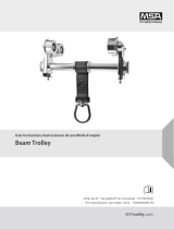
7
W L
8522028 * 2.77” (70.36 mm) 6.50” (165.10 mm)

FORM NO: 5908278 REV: A
4
SAFETY INFORMATION
Please read, understand, and follow all safety information contained in these instructions prior to the use of this Flexiguard System.
FAILURE TO DO SO COULD RESULT IN SERIOUS INJURY OR DEATH.
These instructions must be provided to the user of this equipment. Retain these instructions for future reference.
Intended Use:
This Flexiguard System is intended for use as part of a complete fall protection or rescue system.
Use in any other application including, but not limited to, material handling, recreational or sports related activities, or other activities not described in
the User Instructions, is not approved by 3M and could result in serious injury or death.
This system is only to be used by trained users in workplace applications.
! WARNING
This Flexiguard System is part of a personal fall protection or rescue system. It is expected that all users be fully trained in the safe installation and
operation of the complete system. Misuse of this system could result in serious injury or death. For proper selection, operation, installation,
maintenance, and service, refer to all Product Instructions and all manufacturer recommendations, see your supervisor, or contact 3M Technical Service.
• To reduce the risks associated with transporting a Flexiguard system which, if not avoided, could result in serious injury or death:
- Ensure the system is properly secured or congured prior to transport. Refer to the User Instructions for detailed transportation requirements.
- Only transport below 5 mph (8 km/h) and at inclines of 10° or less, or as outlined in the User Instructions.
- Ensure the system will not contact overhead objects or electrical hazards while transporting or in use.
• To reduce the risks associated with working with a Flexiguard system which, if not avoided, could result in serious injury or death:
- Inspect all components of the system before each use, at least annually, and after any fall event, in accordance with the User Instructions.
- If inspection reveals an unsafe or defective condition, remove the system from service and repair or replace according to the User Instructions.
- Any system that has been subject to fall arrest or impact force must be immediately removed from service. Refer to the User Instructions or
contact 3M Fall Protection.
- The substrate or structure on which the system is attached/positioned must be able to sustain the static loads specied for the system in the
orientations permitted in the User Instructions or Installation Instructions.
- Do not exceed the number of allowable users as per the User Instructions.
- Never attach to a system until it is fully assembled, positioned, adjusted, and installed. Do not adjust the system while a user is attached.
- Never work outside the safe work area as dened by the User Instructions.
- Do not connect to the system while it is being transported or installed.
- Always maintain 100% tie-off when transferring between anchor points on the system.
- Use caution when installing, using, and moving the system as moving parts may create potential pinch points.
- Ensure proper lockout/tagout procedures have been followed when applicable.
- Only connect fall protection subsystems to the designated anchorage connection point on the system.
- When drilling holes for assembly or installation of the system, ensure no electric lines, gas lines, or other critical materials or equipment will be
contacted by the drill.
- Ensure that fall protection systems/subsystems assembled from components made by different manufacturers are compatible and meet the
requirements of applicable standards, including the ANSI Z359 or other applicable fall protection codes, standards, or requirements. Always
consult a Competent or Qualied Person before using these systems.
• To reduce the risks associated with working at heights which, if not avoided, could result in serious injury or death:
- Ensure your health and physical condition allow you to safely withstand all of the forces associated with working at height. Consult with your
doctor if you have any questions regarding your ability to use this equipment.
- Never exceed allowable capacity of your fall protection equipment.
- Never exceed maximum free fall distance of your fall protection equipment.
- Do not use any fall protection equipment that fails pre-use or other scheduled inspections, or if you have concerns about the use or suitability
of the equipment for your application. Contact 3M Technical Services with any questions.
- Some subsystem and component combinations may interfere with the operation of this equipment. Only use compatible connections. Consult
3M prior to using this equipment in combination with components or subsystems other than those described in the User Instructions.
- Use extra precautions when working around moving machinery (e.g. top drive of oil rigs) electrical hazards, extreme temperatures, chemical
hazards, explosive or toxic gases, sharp edges, or below overhead materials that could fall onto you or the fall protection equipment.
- Use Arc Flash or Hot Works devices when working in high heat environments.
- Avoid surfaces and objects that can damage the user or equipment.
- Ensure there is adequate fall clearance when working at height.
- Never modify or alter your fall protection equipment. Only 3M or parties authorized in by 3M may make repairs to the equipment.
- Prior to use of fall protection equipment, ensure a rescue plan is in place which allows for prompt rescue if a fall incident occurs.
- If a fall incident occurs, immediately seek medical attention for the fallen worker for the worker who has fallen.
- Do not use a body belt for fall arrest applications. Use only a Full Body Harness.
- Minimize swing falls by working as directly below the anchorage point as possible.
- If training with this device, a secondary fall protection system must be utilized in a manner that does not expose the trainee to an unintended
fall hazard.
- Always wear appropriate personal protective equipment when installing, using, or inspecting the device/system.
EN

5
;
Prior to installation and use of this equipment, record the product identication information from the ID label in the
Inspection and Maintenance Log at the back of this manual.
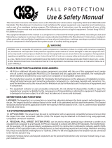
PRODUCT DESCRIPTION:
The Counterweight Rail Fall Arrest System combines easy access to elevated work areas with fall protection from the ground
for the duration of the work performed. The system includes a Horizontal Rail Assembly with Trolleys that ride in Track Rails to
any position along the Rail Assembly. The Trolleys serve as attachment points for the anchorage of a Personal Fall Arrest System
(PFAS). The system can be moved by use of a lift truck or maintenance vehicle when equipped with proper accessories.
Figure 1 illustrates components of the Counterweight Rail Fall Arrest System. See Table 1 for Component Specications. Table 1
stipulates the required amount of counterweight for use.
Table 1 – Specications
System Specications:
Capacity: 2 person up to 310 lbs (141 kg) each
Anchorage: Structure supporting the Counterweight Trailer Fall Arrest System must withstand a 15,500 lb (68.9 kN) vertical load.
Offset: 8 ft (2.43 m)
Total System
Weight:
Approximately 11,850 lb. (5,375 kg) with Concrete. Approximately 5,050 lbs (2,291 kg) with concrete removed.
Counterweight
Required
Min. 6,800 lbs (3084.4 kg)
Recommended two 4000 psi (27.6 Mpa) concrete blocks, 2’x2’x6’ (60cm x 60cm x 182cm)
Component Specications:
Figure 1
Reference Component Materials Note:
A
Primary Forklift Pockets Steel Tube
B
Alternate Forklift Pockets Steel Tube
C
Leveling Jack
Body & Hardware - Steel
Cable - 1/16” SS
D
Safety Labels Vinyl
E
Vertical Support Beams Steel
F
Rail Supports Aluminum
G
Glide Rail Aluminum
Maximum Capacity: 2 person up to 310 lbs each (141 kg)
including clothes, tools, etc. per Boom Arm and Anchorage
Connection Point
H
Slope Indicator Plastic
I
Counterweight Concrete 2X Weights with Concrete: 3,400 lb (1,542 kg) each
J
Tie Back Supports Aluminum
1 Anchorage Connection Points: Each Anchorage Connection Point has been tested and veried to a safety factor of 2:1 per OSHA.

6
1.0 PRODUCT APPLICATION
1.1 PURPOSE: Flexiguard
™
Anchorage Systems are designed to provide anchorage connection points for a Personal Fall Arrest
System (PFAS).
1.2 SUPERVISION: Installation of this equipment must be supervised by a Qualied Person
1
. Use of this equipment must be
supervised by a Qualied Person
1
.
1.3 TRAINING: This equipment must be installed and used by persons trained in its correct application. This manual is to be
used as part of an employee training program as required by OSHA. It is the responsibility of the users and installers of
this equipment to ensure they are familiar with these instructions, trained in the correct care and use of this equipment,
and are aware of the operating characteristics, application limitations, and consequences of improper use of this
equipment.
1.4 RESCUE PLAN: When using this equipment and connecting subsystem(s), the employer must have a rescue plan and
the means at hand to implement and communicate that plan to users, authorized persons
2
, and rescuers
3
. A trained, on-
site rescue team is recommended. Team members should be provided with the equipment and techniques to perform a
successful rescue. Training should be provided on a periodic basis to ensure rescuer prociency.
1.5 INSPECTION FREQUENCY:
The Flexiguard
Anchorage System
shall be inspected by the user before each use and,
additionally, by a competent person other than the user at intervals of no longer than one year.
4
Inspection procedures are
described in the “Inspection and Maintenance Log”. Results of each Competent Person inspection should be recorded on
copies of the “Inspection and Maintenance Log”.
1.6 AFTER A FALL: If the Flexiguard Anchorage System is subjected to the forces of arresting a fall, it must be removed from
the eld of service immediately and replaced or inspected by an Authorized 3M Representative.
2.0 SYSTEM CONSIDERATIONS
2.1 ANCHORAGE: Structure on which the Flexiguard Anchorage System is placed or mounted must meet the Anchorage
specications dened in Table 1.
2.2 PERSONAL FALL ARREST SYSTEM: Figure 1 illustrates the application of this Flexiguard Anchorage System. Personal
Fall Arrest Systems (PFAS) used with the system must meet applicable OSHA, ANSI, state, and federal requirements. The
PFAS shall incorporate a Full Body Harness and Self-Retracting Device (SRD) with a 900 lb (4 kN) Maximum Arresting
Force.
2.3 FALL PATH AND SRL LOCKING SPEED: A clear path is required to assure positive locking of an SRL. Situations which
do not allow for an unobstructed fall path should be avoided. Working in confined or cramped spaces may not allow the
body to reach sufficient speed to cause the SRL to lock if a fall occurs. Working on slowly shifting material, such as sand
or grain, may not allow enough speed buildup to cause the SRL to lock.
2.4 HAZARDS: Use of this equipment in areas with environmental hazards may require additional precautions to prevent
injury to the user or damage to the equipment. Hazards may include, but are not limited to: heat, chemicals, corrosive
environments, high voltage power lines, explosive or toxic gases, moving machinery, sharp edges, or overhead materials
that may fall and contact the user or Personal Fall Arrest System.
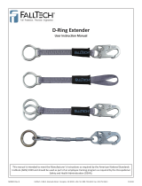
2.5 FALL CLEARANCE: There must be sufcient clearance below the user to arrest a fall before the user strikes the ground
or other obstruction. Fall Clearance is dependent on the following factors:
• Deceleration Distance • Worker Height • Elevation of Anchorage Connector
• Free Fall Distance • Movement of Harness Attachment Element • Connecting Subsystem Length
See the Personal Fall Arrest System manufacturer’s instructions for specics regarding Fall Clearance calculation.
2.6 SWING FALLS: Swing Falls occur when the anchorage point is not directly above the point where a fall occurs (see).
The force of striking an object in a swing fall may cause serious injury or death. Minimize swing falls by working as
directly below the anchorage point as possible. Do not permit a swing fall if injury could occur. Swing falls will signicantly
increase the clearance required when a Self-Retracting Device or other variable length connecting subsystem is used.
2.7 SHARP EDGES: Avoid working where Lifeline or Lanyard components of the Personal Fall Arrest System (PFAS) can
contact or abrade against unprotected sharp edges (see Figure 4). Where contact with a sharp edge is unavoidable, cover
the edge with protective material (A).
2.8 COMPONENT COMPATIBILITY: 3M equipment is designed for use with 3M approved components and subsystems
only. Substitutions or replacements made with non-approved components or subsystems may jeopardize compatibility of
equipment and may effect the safety and reliability of the complete system.
1 Qualied Person: A person with a recognized degree of professional certicate and with extensive knowledge, training, and experience in the fall protection
and rescue eld who is capable of designing, analyzing, evaluating, and specifying fall protections and rescue systems to the extent required by OSHA and other ap-
plicable standards.
2 Authorized Person: For purposes of the Z359 standards, a person assigned by the employer to perform duties at a location where the person will be exposed
to a fall hazard.
3 Rescuer: Person or persons other than the rescue subject acting to perform an assisted rescue by operation of a rescue system.
4 Inspection Frequency: Extreme working conditions (harsh environments, prolonged use, etc.)may require increasing the frequency of competent person
inspections.

7
2.9 CONNECTOR COMPATIBILITY: Connectors are considered to be compatible with connecting elements when they
have been designed to work together in such a way that their sizes and shapes do not cause their gate mechanisms to
inadvertently open regardless of how they become oriented. Contact 3M if you have any questions about compatibility.
Connectors (hooks, carabiners, and D-rings) must be capable of supporting at least 5,000 lbs. (22.2 kN). Connectors
must be compatible with the anchorage or other system components. Do not use equipment that is not compatible.
Non-compatible connectors may unintentionally disengage (see Figure 5). Connectors must be compatible in size, shape,
and strength. If the connecting element to which a snap hook or carabiner attaches is undersized or irregular in shape, a
situation could occur where the connecting element applies a force to the gate of the snap hook or carabiner (A). This force
may cause the gate to open (B), allowing the snap hook or carabiner to disengage from the connecting point (C).
Self-locking snap hooks and carabiners are required by ANSI Z359 and OSHA.
2.10 MAKING CONNECTIONS: Snap hooks and carabiners used with this equipment must be self-locking. Ensure all
connections are compatible in size, shape and strength. Do not use equipment that is not compatible. Ensure all
connectors are fully closed and locked.
3M connectors (snap hooks and carabiners) are designed to be used only as specied in each product’s user’s instructions.
See Figure 6 for examples of inappropriate connections. Do not connect snap hooks and carabiners:
A. To a D-ring to which another connector is attached.
A. In a manner that would result in a load on the gate. Large throat snap hooks should not be connected to standard
size D-rings or similar objects which will result in a load on the gate if the hook or D-ring twists or rotates, unless the
snap hook complies is equipped with a 3,600 lb (16 kN) gate. Check the marking on your snap hook to verify that it
is appropriate for your application.
B. In a false engagement, where features that protrude from the snap hook or carabiner catch on the anchor, and
without visual conrmation seems to be fully engaged to the anchor point.
C. To each other.
D. Directly to webbing or rope lanyard or tie-back (unless the manufacturer’s instructions for both the lanyard and
connector specically allows such a connection).
E. To any object which is shaped or dimensioned such that the snap hook or carabiner will not close and lock, or that
roll-out could occur.
F. In a manner that does not allow the connector to align properly while under load.

8
3.0 INSTALLATION
;
Installation of the Flexiguard™ Counterweight Rail Fall Arrest System (FAS) must be supervised by a Qualied
Person. The installation must be certied by a Qualied Person as meeting the criteria for a Certied Anchorage, or that
it is capable of supporting the potential forces that could be encountered during a fall.
1
;
This system is designed to be used on level ground only. If you have any questions regarding the safe terrain for
system installation and operation, please contact 3M.
3.1 PLANNING: Plan your fall protection system prior to installation of the Counterweight Rail Fall Arrest System (FAS).
Account for all factors that may affect your safety before, during and after a fall. Consider all requirements, limitations
and specications as dened in Sections 1 and 2.
3.2 ASSEMBLY: See IFU 5903234 for system assembly steps.
3.3 FOUR-WHEELED, SMALL-EYED SRD TROLLEYS: Glide Rail Trolley options vary and are based on the applicable trolley
frame system requirements.
;
Connection point for SRDs attached with an approved Double-Locking Carabiner. Small eye minimizes loss of
overhead clearance, keeping the worker’s attachment point as high as possible relative to their dorsal D-Ring. Model
Number and dimensions are specied in Figure 7.
;
After the Trolleys have been fully installed, reinspect all components for damage, correct orientation, and proper
torque on all nuts and bolts. Attach the intended fall arrest equipment (SRDs, Lanyards, etc.) to each Trolley and walk
the Trolley the entire length of the Track Assembly to ensure the Trolley Wheels travel smoothly in the Track.
4.0 USE
;
This system is designed to be used on level ground only. If you have any questions regarding if your terrain is safe
for system use, please contact 3M. Do not attempt to adjust the height of the rail system by setting items under the
leveling feet to gain more height. The Fixed-Height rail system must only be used when all four (4) leveling feet are
safely touching the ground.
4.1 BEFORE EACH USE: Verify that your work area and Personal Fall Arrest System (PFAS) meet all criteria dened in
Section 2 and a formal Rescue Plan is in place. Inspect the Counterweight Rail Fall Arrest System FAS per the ‘User’
inspection points dened on the ‘Inspection and Maintenance Log’ (Table 2). If inspection reveals an unsafe or defective
condition, do not use the system. Remove the system from service and contact 3M regarding replacement or repair.
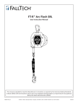
;
SAFE WORK AREA: Figure 2 illustrates the Safe Work Area for the Fall Arrest System. Try to work directly below
the Anchorage Connection Point to minimize Swing Fall. The angle of the Self-Retracting Lifeline should never be more
than 30° from vertical and the Horizontal Distance between the anchorage connection point and the worker should not
be greater than 6 ft (1.82 m).
4.2 USING THE COUNTERWEIGHT HORIZONTAL RAIL SYSTEM:
Step 1. Position the Counterweight Horizontal Rail System over the desired work area/object. Place the unit into position so
the Rail Assembly is centered in the work area to maximize the effective safe work area (See Figure 2), and reduce
the potential for a fall. The Leveling Feet must be positioned over a stable, level surface capable of supporting the
weight of the rail system.
Step 2. Secure and level the Counterweight Horizontal Rail System: Use the level supplied with the system to determine if the
system is resting level on the work surface. If uneven terrain is present, use the integrated jack assemblies to level
the system. Do not use the rail system if the system is not level within 1 degree in any direction.
Step 3. Don a Full Body Harness: Don a Full Body Harness per the manufacturer’s instructions.
Step 4. Connect the SRD Lifeline to the Full Body Harness: Connect the Self Locking Snap Hook or Self Locking/Self
Closing Carabiner on the end of the SRD Lifeline to the Front or Back D-Ring on the Full Body Harness. To ensure a
safe connection, always follow the instructions provided in the SRD and Full Body Harness manufacturers’ instructions
and observe the requirements in Section 2 of this manual regarding Compatibility of Connectors and Connections.
Step 5. When attached to the SRD: The worker is free to move about within recommended working areas at normal speeds.
The Trolley should roll freely in the Rail Assembly. The Lifeline should extend smoothly and retract without hesitation.
If slack line condition is created in normal use, the unit should be inspected and serviced by an authorized service
center. Should a fall occur, the SRD will lock and arrest the fall. Upon rescue, remove the SRD from use. Inspect as
described in manufacturer’s instructions. When working with the SRD, allow the lifeline to recoil back into the device
under control. Allowing the lifeline to be fully extended for long periods of time may cause premature weakening of the
retraction spring.
;
The maximum number of people that may be attached to the Counterweight Horizontal Frame System is stated
by the system labelling; each using an individual Trolley and SRD. No more than one (1) person should be attached
to a single Trolley at any time.
;
The SRD line must not drag or bend over a leading edge while accessing the work area. To eliminate that
problem reposition the unit. Follow the SRD manufacturer’s instructions carefully.

9
5.0 TRAINING
It is the responsibility of the user to assure they are familiar with these instructions, and are trained in the correct
care and use of this equipment. Users must also be aware of the operating characteristics, application limits, and the
consequences of improper use of this equipment.
6.0 INSPECTION
6.1 INSPECTION FREQUENCY: The Flexiguard
Fall Arrest System must be inspected at the intervals dened in Section 1.
Inspection procedures are described in the “Inspection and Maintenance Log”. Inspect all other components of the Fall
Protection System per the frequencies and procedures dened in the manufacturer’s instructions.
;
Some Flexiguard Fall Arrest Systems are equipped with a Radio Frequency Identication (RFID) Tag. The RFID Tag
can be used in conjunction with a Handheld Reading Device to simplify inspection and inventory control and provide
records for your fall protection equipment.
6.2 DEFECTS: If inspection reveals an unsafe or defective condition, remove the Fall Arrest System from service immediately
and contact 3M regarding replacement or repair. Do not attempt to repair the Fall Arrest System.
;
Only 3M or parties authorized in writing by 3M may make repairs to this equipment.
6.3 PRODUCT LIFE: The functional life of the Fall Arrest System is determined by work conditions and maintenance. As long
as the product passes inspection criteria, it may remain in service.
7.0 MAINTENANCE, SERVICING, STORAGE
7.1 CLEANING: Periodically clean the Fall Arrest System’s metal components with a soft brush, warm water, and a mild soap
solution. Ensure parts are thoroughly rinsed with clean water.
;
Although highly resistant to chemicals and environmental conditions, avoid contaminating the Flexiguard
Fall Arrest System with acids, bitumen, cement, paint, cleaning uids, etc. If the equipment contacts acids or other
caustic chemicals, remove from service and wash with water and a mild soap solution. Inspect per Table 2 before
returning to service.
7.2 SERVICE: Only 3M or parties authorized in writing by 3M may make repairs to this equipment. If the Flexiguard
Fall Arrest System has been subject to fall force or inspection reveals an unsafe or defective conditions, remove the
system from service and contact 3M regarding replacement or repair.
7.3 STORAGE AND TRANSPORT: When not in use, store and transport the Fall Arrest System and associated fall protection
equipment in a cool, dry, clean environment out of direct sunlight. Avoid areas where chemical vapors may exist.
Thoroughly inspect components after extended storage.

10
8.0 LABELS
Labels must be replaced if they are not fully legible.
9511857 Rev. A
APPROXIMATE WEIGHT
11,850 LBS / 5,375 kg
WARNING
9511857
9510749 REV B
FlexiGuard
CUSTOM FALL
PROTECTION SOLUTIONS
TM
PORTABLE COUNTERWEIGHTED
RAIL SYSTEM
STEP 1: ENGAGE THE FRONT OR SIDE FORK POCKETS WITH A
FORKLIFT CAPABLE OF SUPPORTING THE ENTIRE SYSTEM WEIGHT.
STEP 2: POSITION SYSTEM SO THAT GLIDERAIL IS OVER THE
DESIRED WORK SURFACE. ONCE IN PLACE, ROTATE EACH
STABILIZING JACK UNTIL THE SYSTEM IS LEVEL.
STEP 3: PULL DOWN THE TAG LINE TO CONNECT TO THE SRL (NOT
PROVIDED) USING A FULL BODY HARNESS.
STEP 4: SYSTEM USERS MUST STAY WITHIN THE SAFE WORKING
AREA. SEE FIGURE 1
WARNING
R
FIGURE 1
SAFE WORKING AREA
OPERATORS INSTRUCTIONS
PERSONS
• THIS SYSTEM IS APPROVED FOR USE WITH RETRACTABLE DEVICES
AND SHOCK ABSORBERS WITH A MAXIMUM ARRESTING FORCE(M.A.F.)
RATING OF 900 lb (4kN) OR LESS.
• TRANSFERRING FROM ONE SRL TO ANOTHER MUST BE DONE SO
YOU ARE ATTACHED TO AT LEAST ONE SRL AT ALL TIMES.
• NO MORE THAN ONE PERSON MAY BE ATTACHED TO A GLIDE RAIL
TROLLEY AT ANY GIVEN TIME. SEE BELOW TO DETERMINE THE
MAXIMUM NUMBER OF PERSONS ABLE TO USE THIS SYSTEM. NEVER
EXCEED THE MAXIMUM USER RATING.
• ALL USERS MUST READ AND UNDERSTAND THE INSTRUCTIONS
PRIOR TO USING THIS SYSTEM.
• BEWARE OF OVERHEAD POWER LINES
OR OTHER HAZARDS WHICH MAY CAUSE
ELECTRIC SHOCK.
• SYSTEM MUST BE WITHIN 1 DEGREE OF
LEVEL PRIOR TO USE.
• THE CORRECT AMOUNT OF COUNTER-
WEIGHT MUST BE INSTALLED PRIOR TO
THIS MAN-RATED SYSTEM IS DESIGNED FOR
A MAXIMUM OF
USER CAPACITY IN ACCORDANCE WITH
MANUFACTURER’S INSTRUCTIONS. FAILURE
TO COMPLY MAY RESULT IN SERIOUS INJURY
OR DEATH.
2
6’
6’
6’
6’
SAFE WORKING AREA SAFE WORKING AREA
COUNTERWEIGHT
PAD
9510749
9505175
9504547
9502313

Table 2 – Inspection and Maintenance Log
Inspection Date: Inspected By:
Components: Inspection: (See Section 6 for Inspection Frequency) User
Competent
Person
Flexiguard
System
Inspect structural components for signicant rust or corrosion that may affect the structural
integrity of the fall protection system. Minor cosmetic surface rust or surface corrosion that has
developed over time is acceptable on certain areas of the system. Any areas of concern should
be reviewed by a Qualied Person
1
(or contact 3M).
Inspect Jacks &
Counterweight
Inspect the Jacks for cracks, dents, bends, etc. Ensure the appropriate amount of counterweight
is in place. (See Table 1.)
Inspect hardware
Verify there are no loose nuts and bolts on the system and all pins are in place.
Tighten all loose bolts to the proper torque specications.
Labels
Verify that all labels are securely attached and are legible. (See ‘Labels’.)
PFAS and Other
Equipment
Additional Personal Fall Arrest System (PFAS) equipment (harness, SRD, etc) that are used with
the Flexiguard Anchorage System should be installed and inspected per the manufacturer’s
instructions.
Serial Number(s): Date Purchased:
Model Number: Date of First Use:
Corrective Action/Maintenance: Approved By:
Date:
Corrective Action/Maintenance: Approved By:
Date:
Corrective Action/Maintenance: Approved By:
Date:
Corrective Action/Maintenance: Approved By:
Date:
Corrective Action/Maintenance: Approved By:
Date:
Corrective Action/Maintenance: Approved By:
Date:
Corrective Action/Maintenance: Approved By:
Date:
Corrective Action/Maintenance: Approved By:
Date:
1 Qualied Person: A person with a recognized degree of professional certicate and with extensive knowledge, training, and experience in the fall protection
and rescue eld who is capable of designing, analyzing, evaluating, and specifying fall protections and rescue systems to the extent required by OSHA and other
applicable standards.

USA
3833 SALA Way
Red Wing, MN 55066-5005
Toll Free: 800.328.6146
Phone: 651.388.8282
Fax: 651.388.5065
Brazil
Rua Anne Frank, 2621
Boqueirão Curitiba PR
81650-020
Brazil
Phone: 0800-942-2300
Mexico
Calle Norte 35, 895-E
Col. Industrial Vallejo
C.P. 02300 Azcapotzalco
Mexico D.F.
Phone: (55) 57194820
Colombia
Compañía Latinoamericana de Seguridad S.A.S.
Carrera 106 #15-25 Interior 105 Manzana 15
Zona Franca - Bogotá, Colombia
Phone: 57 1 6014777
Canada
260 Export Boulevard
Mississauga, ON L5S 1Y9
Phone: 905.795.9333
Toll-Free: 800.387.7484
Fax: 888.387.7484
EMEA (Europe, Middle East, Africa)
EMEA Headquarters:
Le Broc Center
Z.I. 1re Avenue - BP15
06511 Carros Le Broc Cedex
France
Phone: + 33 04 97 10 00 10
Fax: + 33 04 93 08 79 70
Australia & New Zealand
95 Derby Street
Silverwater
Sydney NSW 2128
Australia
Phone: +(61) 2 8753 7600
Toll-Free : 1800 245 002 (AUS)
Toll-Free : 0800 212 505 (NZ)
Fax: +(61) 2 8753 7603
Asia
Singapore:
1 Yishun Avenue 7
Singapore 768923
Phone: +65-6450 8888
Fax: +65-6552 2113
Shanghai:
19/F, L’Avenue, No.99 Xian Xia Rd
Shanghai 200051, P R China
Phone: +86 21 62539050
Fax: +86 21 62539060
Korea:
3M Koread Ltd
20F, 82, Uisadang-daero,
Yeongdeungpo-gu, Seoul
Phone: +82-80-033-4114
Fax: +82-2-3771-4271
Japan:
3M Japan Ltd
6-7-29, Kitashinagawa, Shinagawa-ku, Tokyo
Phone: +81-570-011-321
Fax: +81-3-6409-5818
WEBSITE:
3M.com/FallProtection
ISO
9001
FM534873
EU DECLARATION OF CONFORMITY:
3M.com/FallProtection/DOC
U.S. PRODUCT WARRANTY, LIMITED REMEDY
AND LIMITATION OF LIABILITY
WARRANTY: THE FOLLOWING IS MADE IN LIEU OF ALL WARRANTIES OR CONDITIONS, EXPRESS
OR IMPLIED, INCLUDING THE IMPLIED WARRANTIES OR CONDITIONS OF MERCHANTABILITY OR
FITNESS FOR A PARTICULAR PURPOSE.
Unless otherwise provided by applicable law, 3M fall protection products are warranted against factory
defects in workmanship and materials for a period of one year from the date of installation or fi rst use
by the original owner.
LIMITED REMEDY: Upon written notice to 3M, 3M will repair or replace any product determined by
3M to have a factory defect in workmanship or materials. 3M reserves the right to require product be
returned to its facility for evaluation of warranty claims. This warranty does not cover product damage
due to wear, abuse, misuse, damage in transit, failure to maintain the product or other damage beyond
3M’s control. 3M will be the sole judge of product condition and warranty options.
This warranty applies only to the original purchaser and is the only warranty applicable to 3M’s fall
protection products. Please contact 3M’s customer service department at 800-328-6146 or via email at
3MF[email protected] for assistance.
LIMITATION OF LIABILITY: TO THE EXTENT PERMITTED BY APPLICABLE LAW, 3M IS NOT
LIABLE FOR ANY INDIRECT, INCIDENTAL, SPECIAL OR CONSEQUENTIAL DAMAGES INCLUDING,
BUT NOT LIMITED TO LOSS OF PROFITS, IN ANY WAY RELATED TO THE PRODUCTS REGARDLESS
OF THE LEGAL THEORY ASSERTED.
/