
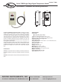
WIRING INSTRUCTIONS
Wiring diagram is displayed on the inside cover of the unit and in figure
1.
NOTICE: If the length of the probe cables measures more than 100
meters, a recalibration adjustment must be made (parameter P1).
NOTICE: Avoid installing the probe cables in proximity with any power
cables.
PROGRAMMING PARAMETERS
In order to adjust parameters, jumper must be set in unlocked position.
Access only to Set Points SP (without software code protection):
• Press and release SET. Parameter SP appears on the display.
• Press SET to see the value of the parameter.
• Modify the value using the UP and DOWN keys.
• Press SET Key to save the value.
• Press SET and DOWN to quit programming, or wait 1 minute for the
TIMEOUT.
Access to all parameters (software code protected):
• Press SET for 8 seconds. The access code value 0 is shown on the
display.
• Using the UP and DOWN buttons, set the code (factory-set code is 0).
• Press SET to confirm the code. If it is correct, the first parameter label
will be shown on the display (SP).
• Move to the desired parameter with the UP and DOWN keys.
• Press SET to see the value of the parameter.
• Modify the value with the UP and DOWN keys.
• Press SET to save and exit parameter list.
• Press SET and DOWN to quit programming, or wait 1 minute for the
TIMEOUT.
Resetting the parameter pass code
The parameter code can be set to zero by holding the SET key and
cycling power to the unit.
LED INDICATIONS
This indicates that the output is energized or that the compressor is
connected. It waits for the programmed minimum stop time of the
compressor.
This indicates that defrosting is activated.
Error Messages
In normal operation, the probe temperature will be shown. In case of
alarm or error, the following messages will be shown:
• Er- Memory error.
• -- Shorted-circuited probe error.
• oo- Open probe error.
PARAMETER DESCRIPTIONS
SP = Set Point. Temperature desired to regulate the machine. Can vary
from r1 to r2.
r0 = Differential. Heating: If temperature is ≥ SP then output is OFF. If
temperature is < SP - r0 then output is ON. Cooling: If temperature is ≥
SP + r0 then output is ON. If temperature is < SP then output is OFF.
r1 = Lower Set Point Limit.
r2 = Upper Set Point Limit.
d0 = Heat or Cooling Control. Ht = heating control, Co = cooling con-
trol.
d2 = Defrosting Time Remaining, in minutes. If d2 = 0, defrosting will
not start.
d8 = Interval Between Two Defrostings, in hours.
c0 = Minimum Time for Compressor to be OFF. Minimum time for
compressor to stop until it can start again.
c1 = Continuous Cycle Time. The remaining time for a continuous cold
cycle.
c2 = ON Time of fault cycle, during probe error.
c3 = OFF Time of fault cycle, during probe error.
P0 = Selection of Engineering units between F and C.
P1 = Ambient Probe Calibration. Offsets temperature in degrees to
adjust the ambient probe.
H5 = Access Code to Parameters. Factory-set to 0.
H6 = Selection of Input Probe Type: PTC or NTC.
t0 = Temperature Display Limit. Maximum temperature shown on the
display, although the real temperature can be greater.
OPERATION IN CASE OF ERROR
If the probe or thermostat memory should fail, the compressor will be
connected in accordance to the parameters set in C2 and C3.
MAINTENANCE/REPAIR
Upon final installation of the Series TSW, no routine maintenance is
required. The Series TSW is not field serviceable and should be returned
if repair is needed. Field repair should not be attempted and may void
warranty.
WARRANTY/RETURN
Refer to “Terms and Conditions of Sales” in our catalog and on our web-
site. Contact customer service to receive a Return Goods Authorization
number before shipping the product back for repair. Be sure to include a
brief description of the problem plus any additional application notes.
Dwyer Instruments,Inc.
Attn: Repair Department
102 Highway 212
Michigan City, IN 46360 U.S.A.
S
P
r0
r1
r
2
d
0
d
2
d8
c0
c1
c
2
c
3
P
0
P
1
H5
H6
t0
D
escription
S
et Point
Differential or hysteresis
Lower value for set point
H
igher value for set point
H
eating or Cooling Control
T
ime for Defrosting
Interval time between Defrosts
Minimum stop time for compressor
Continuous cycle time
O
n time of fault cycle
O
ff time of fault cycle
E
ngineering Units
A
mbient Probe Adjustment
Parameter acess code
Probe Input Type
Maximum Temperature on Display
U
nits
D
egrees
Degrees
Degrees
D
egrees
O
ption
M
inutes
Hours
Minutes
Hours
M
inutes
M
inutes
O
ption
D
egrees
Number
Option
Degrees
R
ange
r
1 to r2
1 to 20°
-50 to 150°C
-50 to 302°F
-
50 to 150°C
-
50 to 302°F
H
t/Co
0
to 59
0 to 24
0 to 59
0 to 24
0
to 999
0
to 999
°
C/°F
-
10 to 10°
0 to 99
Ptc/ntc
-50 to 150°C
-
50 to 302°F
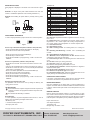
PROBE
INPUTS
2 37 8 9 10 11
OUTPUTS
Sd1
TS2-K
O
UT 1
POWER
SUPPLY
F
igure 1
F
igure 2
Locked Unlocked
Parameter List
©Copyright 2014 Dwyer Instruments, Inc. Printed in U.S.A. 7/14 FR# R0-443773-00 Rev. 2
DWYER INSTRUMENTS, INC.
Phone: 219/879-8000 www.dwyer-inst.com
P
.O.
BOX
373
•
MICHIGAN
CITY
,
INDIANA
46360,
U.S.A.
Fax:
219/872-9057
e-mail:
[email protected]

 1
1
 2
2

