
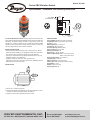
Bulletin PC-VBS
The Series VBS Vibration Switch is small, compact, and uses two easy
set up dials that adjust the maximum RMS velocity set point and false trip
time delay. The Series VBS is intended to continuously monitor the
changes in a machine’s vibration level. The VBS takes real-time RMS
vibration input and provides an analog output of velocity, as well as a
switching output when an alarm value is exceeded.
SAFETY INSTRUCTIONS
• Please read the product description prior to setup of the unit. Ensure
that the product is suitable for your applications without any restrictions.
• The unit conforms to the relevant regulations and EC directives.
• Improper or unintended use may lead to malfunctions of the unit or to
unwanted effects in your application.
• Installation, electrical connection, setup, operation and
maintenance of the unit must only be carried out by qualified personnel
authorized by the machine operator.
INSTALLATION
1. Mount only in a thick housing wall.
2. Ensure a safe vibration transmission and the signal direction is correct,
and allow no elastic intermediate layers. See Figure 1.
3. Tighten the sensor with a tightening torque of 15 Nm.
Specifications - Installation and Operating Instructions
Series VBS Vibration Switch
SPECIFICATIONS
Housing Material: PBT, PC, FPM, and 316 SS.
Temperature Limit: -22 to 221°F (-30 to 105°C).
Accuracy: < ±3%.
Measuring Range: 0 to 50 mm/s.
Connections: M12 connector.
Enclosure Rating: NEMA 6 (IP67).
Electrical Rating: 18 to 32 VDC.
Mounting Orientation: All.
Nonlinearity: < ±0.25% of span.
Switch Output Range: VBS-1: 0 to 25 mm/s Vrms;
VBS-2: 0 to 50 mm/s Vrms.
Analog Output Range: 10 to 1000 Hz.
Output Signal: 4 to 20 mA.
Switch Time Delay: 1 to 60 seconds.
Switch Type: PNP normally open (500 mA max).
Repeatability: < 0.5%.
Weight: 0.25 lb (0.114 kg).
Agency Approval: CE.
DWYER INSTRUMENTS, INC.
Phone: 219/879-8000 www.dwyer-inst.com
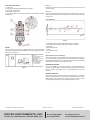
1-1/32˝
[25.91]
M8 CONNECTION
(316 SS)
M
12X1
4
PIN CONNECTION
1-1/16˝
[26.87]
2
-1/2˝
[
63.67]
2
-7/8˝
[
73.05]
VBS-X
s
ec
s
ec
Delay Set
1
0
15
POWER
CKING
m
m/s
inch/s
R
MS Set
Analog
Out
4...
20
m
A
500 mA
pnp
1
8...
3
2
V
DC
Figure 1

DWYER INSTRUMENTS, INC.
Phone: 219/879-8000 www.dwyer-inst.com
©Copyright 2014 Dwyer Instruments, Inc. Printed in U.S.A. 4/14 FR# R6-443973-00 Rev. 1
OPERATION AND DISPLAY
1. Locking ring
2. Setting rings (manually adjustable after unlocking)
3. LED green: voltage supply
4. M8 process connection
5. LED yellow: lights when switching threshold and time delay exceeded.
See Figure 2.
WIRING
The unit must be connected by a qualified electrician. The national and
international regulations for the installation of electrical equipment must be
adhered to. See Figure 3.
RMS Set
Effective value of the switching threshold, defining the limit value of the
vibration velocity.
Delay Set
Time in seconds during which the limit value must be effectively above the
switching threshold (RMS Set) to activate the switching output (normally
closed pin 4).
Output Behavior
1. Time delay after the switching threshold has been exceeded
2. Time delay after the switching threshold has been exceeded
3. Switch-off
4. Switching threshold
5. Delay
Vss = Vibration velocity
t = time
Implementation of the Time Delays
The time delay starts when the defined switching threshold is exceeded (1)
/ (2). The time delay is cancelled when the value falls below the switching
threshold (without switch-off). The switch-off is triggered when the switching
threshold is exceeded during a full time delay (3).
MAINTENANCE/REPAIR
Upon final installation of the Series VBS no routine maintenance is
required. The Series VBS is not field serviceable and should be returned if
repair is needed. Field repair should not be attempted and may void
warranty.
WARRANTY/RETURN
Refer to “Terms and Conditions of Sales” in our catalog and on our website.
Contact customer service to receive a Return Goods Authorization number
before shipping the product back for repair. Be sure to include a brief
description of the problem plus any additional application notes.
Figure 3
Figure 2
Figure 3
-
 1
1
-
 2
2


Ask a question and I''ll find the answer in the document
Finding information in a document is now easier with AI
Related papers
-
Dwyer Series TDT User manual
-
-
Dwyer Series TSW User manual
-
-
-
-
-
-
-
Mercoid 123 Series User manual