Page is loading ...

© EUROHEAT DISTRIBUTORS (H.B.S) LTD. Nov 2006 E & OE Instructions Part number IN1042 Edition H
1
IN1042
Installation Instructions For
HARMONY
1 & 3
STANFORD
80
Wood and Multifuel Stoves
This Manual Must Always Be Available To The Stove Operator
Serial Number
Part No.
Model Name
This manual must be used in conjunction with document
IN1173 The Wood and Multifuel Chimney and Installation Guide,

© EUROHEAT DISTRIBUTORS (H.B.S) LTD. Nov 2006 E & OE Instructions Part number IN1042 Edition H
2
Contact Details:
Euroheat Distributors (H.B.S). Ltd.
Unit 2,
Court Farm Business Park,
Bishops Frome,
Worcestershire. WR6 5AY.
www.euroheat.co.uk
© EUROHEAT DISTRIBUTORS (H.B.S) LTD. October 2006
Technical Guide IN1173 Edition A
1
Wood and Multifuel Stove
Flue and Installation
Technical Guide
Document No: IN1173 Edition A
info@euroheat.co.uk
The Wood and Multifuel Chimney and Installation Guide.
Document No: IN1173. This guide which is included with the stoves information
pack should be used in conjunction with this manual for installation advice.
Useful organisations
Solid Fuel Association 0845 601 4406 www.solidfuel.co.uk
The National Association of Chimney Sweeps 01785 811732 www.chimneyworks.co.uk
HETAS Ltd. 0845 634 5626 www.hetas.co.uk
The Model Range Explained
Nestor Martin and Euroheat insist on progressive development to produce products which are market leading.
Our aims are to produce stoves with the latest innovations, user friendly operation and highly efficient for lower
cost operation.
This operation manual offers user information for the range of HARMONY 1, HARMONY 3, AND STANFORD 80
In some cases you find references in this document to the model size rather than the models exterior design.
There are two sizes of appliances. Harmony 1, Stanford 80 referred to as size 1. Harmony 3 as size 2. Although
the exterior cloths change between model change, for example the Harmony 1 and the Stanford 80, the
internal workings are the same. The Harmony 1 and Harmony 3 are multifuel models, while the Stanford 80
unless fitted with multifuel kit is only suitable for wood.
Model Identification
You will see on the front page of this document a label which confirms which model you have. This label also
advises you of the stoves unique serial number. This information is also attached to your stove for reference.
Important
Please ensure the warranty registration form is completed if you are the installer and confirm with the user
that it is there responsibility to return it to Euroheat. In this way the model and its history will be recorded for
reference in the future.
For the latest versions of manuals, technical information, accessories and spare parts visit the euroheat web
site.
Whilst we are always happy to assist you, please make sure you have read this manual and The Wood and
Multifuel Chimney and Installation Guide, before contacting the technical support team.
Technical support telephone number 01885 491117. E-mail tech@euroheat.co.uk

© EUROHEAT DISTRIBUTORS (H.B.S) LTD. Nov 2006 E & OE Instructions Part number IN1042 Edition H
3
IMPORTANT
.
The installation of this appliance must comply with all local regulations, including those referring to
national and European Standards before it can be operated. The stove is not suitable for a shared flue.
However, for England and Wales, only, the coming into force on 1st April 2002 of SI 2002 No 440 exempts
the householder from this legal requirement for the installation of solid fuel fired appliance whose rated heat
output is 50kW or less in a building having no more than 3 storeys (excluding any basement) if a Competent
Engineer is employed who is registered under the Registration Scheme for Companies and Engineers involved
in the Installation and Maintenance of Domestic Solid Fuel Fired Equipment operated by HETAS Ltd. These
registered Competent Engineers may also carry out associated building work necessary to ensure that the
installed appliance complies with Building Regulations without involving the Local Authority Building Control
Department.
Improper adjustment, alteration, maintenance or the fitting of replacement parts not recommended by the
manufacturer can cause injury or property damage. Do not operate the stove with faulty seals or damaged
glass.
Due to the high operating temperatures of this appliance it should be located away from pedestrian traffic
and away from furniture and draperies. Do not store paper or wood near the appliance. Any mats and rugs put
in front of the stove should be fire proof and secured to prevent the possibility of tripping.
Advise all persons as to the stove’s high surface temperatures. If it is possible for children or infirm adults to
come into contact with the stove, fit a suitable fire guard.
It is imperative that all air passageways into, out of, and within the appliance are kept clean. All permanent
ventilation into the room provided for the stove must remain clear and unobstructed at all times. Consideration
must be given to the need for extra ventilation if another heating source needing air is to be operated
simultaneously. If an extraction fan is proposed to be fitted to a connecting area of the house, after the stove
has been installed, professional advice should be sought from a qualified engineer.
The user should be advised that the appliance should be inspected regularly and the chimney cleaned at
least annually.
More frequent cleaning may be required and the advice of a qualified chimney sweep should be sought.
Our range of stoves is capable of operating with outstanding efficiency if the flue system is correct. Because
so little heat is wasted to the flue it is possible that moisture within the products of combustion will condense
if the heat losses within the flue way are too great and allow the flue gases to cool. For this reason we
recommend that the stove is fitted with a suitable flue liner, the same diameter as the flue spigot, to prevent
the possibility of acidic damage to the fabric of the chimney and damage to the stove which will reduce the
longevity of the stove.
When correctly installed, the stove is designed to produce heat, safely. It cannot do so if the installation is
less than absolutely stable, constructed of materials suitable for such an installation and consideration has not
been given to the possibility of people with less than ideal common sense operating it.
Have the existing chimney swept by a chimney sweep. Although you will be lining the chimney, any deposits
left in the chimney will cause problems and may become a fire hazard.
Your attention is drawn to the precautions and responsibilities under the Health and Safety at Work Acts,
and whatever new legislation being introduced during the life of this document.

© EUROHEAT DISTRIBUTORS (H.B.S) LTD. Nov 2006 E & OE Instructions Part number IN1042 Edition H
4
Model Flue Size Air Requirement
Equivalent Area as
Approved Document J
Efficiency Net
%
Efficiency
Gross %
Harmony 1 5” (125mm) 1650mm
2
75 69
Harmony 3 6” (153mm) 6050mm
2 74 68
Stanford 80 5” (125mm) 1650mm
2 75 69
Technical Details
Model Name Model Number Heat Output
Nominal
Wood
Weight KG Flue
Draught
Nominal
Heat
Output
Flue Gas
Mass Flow
g/s
Flue Gas
Temperature
Down Stream
of Flue Spigot
deg C
Harmony 1 39692 8kW 155 11pa 7.6 365
Harmony 3 39696 16kW 213 10pa 14.6 365
Stanford 80 39962 8kW 155 11pa 7.6 365
The Flue
It is possible to remove the top baffles to access the flue for cleaning. However we would advise that if at all
possible an external cleaning access is provided. If the chimney has been lined with the same size flue as the
flue pipe it will be possible to sweep from the flue access point. If the flue is of a larger size than the flue pipe
it may not be possible to use a sweeping brush of adequate size. In which case another cleaning access will be
required. For detailed information see IN1173 The Wood and Multifuel Chimney and Installation Guide.
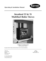
Adjusting thermostat setting
The cold setting of the thermostat must be checked
before the stove is operated for the first time.
The thermostat can be adjusted in two places. A may be
bent for course adjustment and B for fine adjustment.
With the stove cold the gap between the inside left of
the thermostat disc and the cast iron body of the stove
should be 0-1 mm at normal room temperature.
Note: the thermostat disc is designed to close at an
angle.
A
B

© EUROHEAT DISTRIBUTORS (H.B.S) LTD. Nov 2006 E & OE Instructions Part number IN1042 Edition H
5
Changing to Rear Flue Connection
1. Remove flue spigot from top of stove and the flue spigot protector.
2. Remove flue blanking plate from rear of stove.
3. Fit the blanking plate to top of stove with the blanking plate protector. This protection plate is supplied with
the appliance normally located in the ash pan of new models.
4. Fit flue spigot to rear of stove. Do not fit the flue spigot protector.
Flue Spigot
Gasket
Flue Blanking Plate
Gasket
Blanking Plate
Protector
Changing to Top Flue Connection
The procedure is as fitting rear flue but follow the information in reverse and fit the flue spigot protector.
Flue Outlet Configuration
Harmony I, Stanford 80
When using rear flue outlet fit the flue blanking plate
protector before fitting blanking plate. This protection plate
prevents damage to the flue outlet blanking plate.
When using top flue outlet fit the flue spigot protector.
This protector prevents damage to the flue outlet.
Harmony 3
When using top flue outlet fit the flue spigot protector.
This protector prevents damage to the flue outlet.
When using rear flue outlet fit the flue blanking plate
protector before fitting blanking plate. This protection plate
prevents damage to the flue outlet blanking plate.
Flue Blanking Plate Protector
Flue Spigot Protector
Flue Blanking Plate Protector
Flue Spigot Protector

© EUROHEAT DISTRIBUTORS (H.B.S) LTD. Nov 2006 E & OE Instructions Part number IN1042 Edition H
6
Do not be tempted to fit the stove into an unsuitable fireplace. Beyond the requirements of Building
Regulations and access to facilitate servicing the stove, providing a setting which will compliment a stove is
not a luxury, it is the practicality of making the most of an investment. A good builder or fireplace specialist
will be able to transform even the most utilitarian of fireplaces. Whether altering its proportions to those of the
“Golden Mean” ideal, see below, or exposing a wooden or stone lintel or simply removing superfluous detailing
for a comparatively small cost, and the result will be a pleasure for many years.
1
2/3
2/3
1/3 2/3
“Golden Mean”
1. The stove must always stand perfectly level. Adjustment screws and/or triangular plastic levelling spacers
may be provided with the stove. The provision of a suitable level hearth within the recess is an important
consideration when planning a fireplace.
2. Sufficient space should be allowed for service work.
3. At least the minimum clearance from inflammable materials and conforming to the current Building
Regulations.
4. Sufficient space around the stove so that the controls may be operated without the risk of injury to the
operator.
5. Mounting brackets should be installed to facilitate the secure fitting of a fire guard, if one is to be fitted to
protect the young, elderly or infirm.
6. Curtains and soft furnishings should be a minimum of 1m from the stoves body or the surface temperature of
these furnishings must not exceed 65°C.
7. The mounting of expensive paintings, mirrors and plasma screen televisions above a fireplace is not
recommended.
Fireplace Design
Hearths
The stove should stand wholly above a hearth constructed of suitably robust materials and should be able to
accommodate the weight of the appliance and its unsupported flue components. The materials should conform
to local Building Regulations and British Standards.
If the stove is not to stand in a purpose built fireplace recess (this excludes prefabricated constructions) a hearth
made of non-combustible board, steel material, tiles or glass of at least 12mm thick may be used as long as the
floor can accommodate the weight of the appliance and its unsupported flue components.
All our multifuel stoves conform to standards where the hearth temperature does not exceed 100°C. This means°C. This means
a hearth of only 12mm of non combustible material can used. This information only applies to our range of
appliances. Caution do not fit a 12mm hearth to other manufactures products unless documentation is provided
to prove hearth temperatures.

© EUROHEAT DISTRIBUTORS (H.B.S) LTD. Nov 2006 E & OE Instructions Part number IN1042 Edition H
7
In all installations surrounding flammable materials must not exceed 65°C.
Minimum clearance
from flammable materials
A 300mm At least
B 250mm At least
C 300mm At least
D 300mm At least
E 250mm At least
A
B
D
C
E
Stove
Opening of stove
firebox
A
E
E
F
D
Non-combustible fireplace recess
In a fireplace recess Free standing
From Non-combustible Materials.
Distance Required hearth surface
A At least 300mm the edge of which should be clearly defined
B At least 150mm the edge of which should be clearly defined
C At least 150mm the edge of which should be clearly defined
D At least 150mm the edge of which should be clearly defined
E At least 50mm* the edge of which should be clearly defined
F At least 50mm* the edge of which should be clearly defined
Minimum Installation Clearances
Curtains and furnishings should be a minimum of 1m from the
stove or the surface temperature must not exceed 65°C.
From Combustible Materials.
Stove
Opening of stove
firebox
A
B B
C

© EUROHEAT DISTRIBUTORS (H.B.S) LTD. Nov 2006 E & OE Instructions Part number IN1042 Edition H
8
Removing Internal Protection Castings and Grate
Step 1 Removing Top Baffles
Lift the right hand baffle upwards, lifting the rear
more than the front. Move the baffle towards
the stove back to allow the front edge to clear
the supporting ledge and pull forward. The left
baffle removes similarly. To replace the baffles
reverse the procedure, ensuring the front edges
of the baffles are pulled to the front of the stove
and the baffles are as close together as possible.
Step 2 Removing Rear Protection Plates
Remove support bracket retaining screws lift out
protection plates.
Step 3 Removing Side Protection Plates
Remove support bracket retaining screws lift out
protection plates.

© EUROHEAT DISTRIBUTORS (H.B.S) LTD. Nov 2006 E & OE Instructions Part number IN1042 Edition H
9
Step 6 Removing Grate Frame
Remove grate frame. Lift rear edge of grate frame. Lift frame move to the right through side door then remove
through front door.
C
B
A
Step 4 Removing Riddling Links
Remove or loosen rear heat shield
Remove screw “A”
Remove riddling link bar “B”
Remove screws “C” and riddler guide seals.
Step 5 Removing Grate
Lift front of grate remove through front door.

© EUROHEAT DISTRIBUTORS (H.B.S) LTD. Nov 2006 E & OE Instructions Part number IN1042 Edition H
10
Flue draught measured
with the air wash vent
fully open and all other
air supplies to the fire
closed.
Euroheat can supply
the flue measurement
gauges order number
MS026.
Note this is not a
water gauge used to
measure gas pressure.
0.04
0.02
0.06
millimetres
inches
Maximum
firing rate
Minimum
firing rate
Draught Requirements
Draught measured with the air wash vent fully open
and all other air supplies to the stove closed
.09
.08
.07
.06
.05
.04
.03
.02
.01
I
N
.
O
F
W
A
T
E
R
D
R
A
F
T
O
R
P
R
E
S
S
U
R
E
-
L
O
W
R
A
N
G
E
I
N
.
O
F
W
A
T
E
R D
R
A
F
T
O
R
P
R
E
S
S
U
R
E -
H
I
G
H
R
A
N
G
E
.05
.1
.2
.3
.4
.5
.6
.7
.8
.9
1.0
The negative pressure created within the combustion chamber of the stove must be measured using a test hole
drilled into the flue, as close to the stove as possible and before any draught stabilizer that may be fitted to the
flue.
To ensure a constant air inlet size the readings should be taken with both the grate and the thermostatically
controlled air inlet to the stove shut, and the secondary air-wash inlet fully open.
A reading should be taken before the stove is lit to identify any possible problems which may be caused by air
being drawn down the flue by other heating appliances fitted with a flue, extraction fans, etc.. These should be
dealt with before lighting the stove.
Once lit, the stove and flue should be allowed to warm thoroughly before letting the fire burn at a low setting.
While taking the flue draught reading, all air entries to the combustion chamber of the stove should be closed
except the secondary air-wash shutter, which should be fully open. The draught measurement should read
approximately 0.5mm wg.
The stove should now be made to burn at its maximum output and another draught measurement taken, again
closing all air supplies to the stove other than the secondary air-wash shutter. The draught reading when the
burner is operating at its maximum setting should be approximately 1.5mm. wg.
A flue draught which is too low will result in the stove being difficult to light, responding only slowly to
demands for increased output and unable to reach its full heating output.
Flue draught which is too high will make control of the fire difficult, and makes it possible to over fire the
stove, which can seriously damage it. In this instance a flue draught stabiliser may need to be fitted.
The installation manual should be consulted if the flue draught pressure readings are incorrect.

© EUROHEAT DISTRIBUTORS (H.B.S) LTD. Nov 2006 E & OE Instructions Part number IN1042 Edition H
11
Commissioning Check List
Inspect the door and glass seals and ensure all handle latches are adjusted correctly, procedure in the operating
instructions.
Check baffles are installed correctly and that the riddling mechanism is operating.
Ensure that the fire responds to the operation of the controls and that there are no visible emissions of the
combustion products into the room.
Check the flue draught is within the parameters within these instructions. If not fit a suitable flue stabiliser.
Instruct the user on the use of the tools, operation of the appliance and the summer shut down procedure.
Information in the operating instructions.
Instruct the user never to operate the stove with the furnace door open and that the user is aware of the requirement
of a suitable fire guard where children, the old or infirm may come into contact with the appliance.
Hand over the installation instructions, operating instructions and completed warranty form to the user. Remind
the owner to return the warranty form for registration.
Complete the Stoves Registration Form and Pass to User for
Registration
Euroheat, Efel and Nestor Martin have a policy of continual research and development and reserve the right to
modify its appliances without prior notice.
We make every effort to ensure that the information provided in this document is correct and accurate at the
time of printing. Continued updates occur to adapt documents to customer requirements and appliance changes.
For the latest editions of all Euroheat documentation visit our web site
www.euroheat.co.uk.
We would request that you inform Euroheat of information which you feel is not provided in this document which
would assist other users in the future.
The Euroheat Technical Team
Welcome to the world of real Stoves
Euroheat Technical Team
X
Mark box when completed
/