Page is loading ...

© Euroheat Distributors (H.B.S) Ltd. 2000 Instructions Part number IN10111 Edition C
1
Serial Number
Part No.
Technical Help Line
For Installation and Service Advice
Telephone 01885 491117
8.30-12.30 and 1.30-5.30 Week days
Fax 01885 491105 Anytime.
Sales 01885 491111
Euroheat Distributors (H.B.S.) Ltd.,
Unit 2, Court Farm Business Park,
Bishops Frome,
Worcestershire,
WR6 5AY.
01885 490474
Installation Instructions for
Harmony 5
Wood and Coal Stove

© Euroheat Distributors (H.B.S) Ltd. 2000 Instructions Part number IN10111 Edition C
2
INTRODUCTION
The purpose of this technical document is to present, on the basis of the laws of physics involved, the importance
of the drawing power of chimneys and other factors on which the satisfactory functioning of wood & coal heating
equipment depends.
Modern building trends: small-sized rooms, sealed windows and door frames, high thermal output equipment, the
observance of health regulations and clean air fuel products require the whole problem to be reconsidered in its
entirety.
We manufacture a complete heating appliance which has to be connected to a chimney for normal operation. That
chimney when being hot must be capable of providing the air necessary for combustion and fully evacuating the
combustion products.
The installer is responsible under the Health and Safety at Work Act 1974 vi the caustic nature of fire cement and
the possibility of disturbing asbestos in existing installations and to suggest appropriate protection to be given to
the person(s) carrying out the installation.
1) This appliance must be installed by a fully qualified heating engineer. He is responsible to ensure that the
installation is in accordance with all currently accepted British Standards and Codes of Practice, particularly BS6461,
CP403 and BS5449, relating to the installation of solid fuel appliances.
2) The stove must be placed at least 40cm away from any combustible materials. If necessary, any adjoining walls
should be protected from the effects of heat.

© Euroheat Distributors (H.B.S) Ltd. 2000 Instructions Part number IN10111 Edition C
3
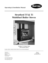
Flue Outlet Options
Optional Front Facing Thermostat Indicator

© Euroheat Distributors (H.B.S) Ltd. 2000 Instructions Part number IN10111 Edition C
4
D. Wind eddies or down-draughts around the top of
the chimney, sometimes due to remote obstacles (hills,
trees, houses, particular architectural arrangements, roof
ridge, etc.) may cause drawing problems.
E. Permanent or temporary excess drawing, also
prejudicial to good combustion (buzzing noise), can be
controlled by a draught regulating flap when excess
draught is experienced at high flow settings. A draught
stabilizer is highly recommended as part of a
standard installation.
F. In all cases the draught of the chimney must be
measured with a draught indicator (gauge) connected to
the flue which runs from the stove to the chimney.
The negative pressure indicated must ideally lie within
the shaded zone on the requirement graph when the
stove is operating smoothly.
Conclusion
Whilst it is obvious that a chimney with adequate drawing
power alone will ensure the satisfactory functioning of
the stove, it should never be forgotten that a large
percentage of problems are caused by faulty drawing
power of chimneys.
CHIMNEY DRAUGHT
For a wood/coal stove to operate normally, it is essential
that the suction of the chimney, which determines the
provision of air to the stove, is continuous and that the
evacuation of the fumes is ensured during combustion.
That is why it is recommended, above all, to check the
state of the chimney to which the stove must be
connected. Once connected it is of the utmost
importance to balance the flue draught to conform the
graph showing draught requirements.
1. THE CHIMNEY
If the chimney is cold, the water in the flue gases will
condense. If it is porous the condensate will appear in
the form of unsightly brown patches on the external
walls of the chimney.
In the event of poor combustion an understanding of
the paragraphs which follow will enable you to solve all
the problems.
A. In naturally aspirated wood/coal stoves the air
necessary for combustion is drawn into the combustion
chamber by the negative pressure of the chimney. The
negative pressure is uniquely due to the fact that the
combustion gases present in the chimney are hot and
lighter than the air outside it. If the chimney is cold,
either because it has not been used for a long time or
because it has no heat insulation or is too short (minimum
4 m), the slow air movement will prevent the flame
burning cleanly. It is always necessary to wait for a while
when there is difficulty in operating until the chimney
has warmed, before deciding that it is the chimney which
is at fault.
B. If inside the house, the stove chimney which is the
natural moving force of the combustion, is competing
with another stronger moving force (the entry of
secondary air into the chimney, another higher or better
insulated chimney, an extractor hood in the kitchen, a
water-heater or a clothes dryer,...) combustion will be
difficult and in the most serious cases smoke and fumes
will even be drawn back into the house. If the house is
too well sealed and the air necessary for combustion
cannot reach the stove, the same malfunction will occur.
In this case, it is not the chimney which is at fault, but
the fact that the room is too well sealed. This is easily
observed by the following symptoms: the flame is weak,
flickers or produces excess smoke. (responds slowly)
The remedy consists of ensuring normal ventilation of
the room in which the appliance is fitted.
This problem can be resolved, in particular, by bringing
in the air necessary for combustion through a pipe of
adequate dimensions leading from outside the premises
close to the stove. Like humans a stove has to breathe.
C. Any obstacle to the easy passage of the combustion
gases through the chimney will be prejudicial to good
drawing and therefore to satisfactory operation. Bends,
turbulence, foreign bodies, dirt, nests, cold walls, etc.-
see the cases shown in the appended diagrams.
A stable chimney draught within the
required parameters is always required.

© Euroheat Distributors (H.B.S) Ltd. 2000 Instructions Part number IN10111 Edition C
5
Planning the chimney
A. The ideal chimney should be vertical, smooth, free
of cracks or foreign bodies. The chimney must be swept
before lining or connection.
Good
Poor
B. To prevent throttling, suction cowls (chimney pots),
or anti-down draught devices must not have a smaller
connecting section than the chimney.
2. The chimney and connection

© Euroheat Distributors (H.B.S) Ltd. 2000 Instructions Part number IN10111 Edition C
6
D. Ceramic or pumice flue liners must be installed with
surrounding insulation. Ideally connecting flue pipe
should fit to the outside of the flue liner. All flue
connections must have the female socket facing upwards,
male connection downwards.
E. It is unfortunately quite common to find that ceramic
(clay) lined flues are installed with no insulation. This
can result in slow, poor operating chimneys which are
inclined to cause condensation and other related
problems. In many cases the solution is to install a flexible
liner.
Good
Poor
C. The chimney outlets should be at least 1 m higher
than the roof ridge or the neighbour's wall. That is to
say that the chimney must not open into a pressure zone,
i.e. between two buildings or under higher trees.

© Euroheat Distributors (H.B.S) Ltd. 2000 Instructions Part number IN10111 Edition C
7
Good
Poor
G. Rear flue connections should be fitted with a tee pipe,
this allows a catchment area for falling soot and debris.
F. Connecting flue pipe must be joined to the chimney
system above the point where the chimney narrows. Flue
gases passing into void areas, turbulise, lose temperature
and so chimney draught.
Cleaning access options
Rear flue connection internal or
external
Top flue connections internal only
Void
Soot,
debris can
block flue

© Euroheat Distributors (H.B.S) Ltd. 2000 Instructions Part number IN10111 Edition C
8
H. Rear flue connections must not be more than 153mm
horizontal. Flue pipe passing through cavity walls should
be sleeved.
I. External flues must be insulated to prevent heat loss.
Good
Poor
J. Large empty spaces should be avoided. Flue
connections must be carefully planned to prevent
problems with voids.
K. Access to the chimney system for inspection or
cleaning should be provided
Good
Poor
Flue must sleeved when
passing through walls
External flues must be insulated

© Euroheat Distributors (H.B.S) Ltd. 2000 Instructions Part number IN10111 Edition C
9
L. Prefabricated flues should be constructed so that the
weight of the chimney is not supported on the stove.
M. In severe excess chimney draught conditions a
draught stabilizer may be required.
Fitting Requirements
1. Stabilizer the same size as flue should be fitted.
2. The stabilizer should be at the end of a horizontal
branch of approximately 100mm.
3. The stabilizer should be fitted no closer than
700mm to the flue outlet of the appliance.
4. The flue stabilizer should be fitted in the same
room as the stove installation.

© Euroheat Distributors (H.B.S) Ltd. 2000 Instructions Part number IN10111 Edition C
10
3. Chimney Cowls
1. Rain Ingress.
To prevent rain penetration into the chimney system and stove. Damp chimney conditions result in poor and slow
draught. Water can also damage the stove especially during periods of none use.
2. Bird Prevention.
Birds have the habit of building nests in chimney terminations. These endeavours often cause partial or complete
blockage of the chimney system.
3. Down Draught Prevention.
Down draughts are normally caused by poorly positioned flue terminations. It is a far better policy to change the
chimney termination location by extension or redesign as severe down draughts will not be prevented by supposed
down draught cowls. In fact many assumptions of down draught are due to serious changes in the flue draught
caused by wind variations on the termination position. (See stabilizer cowls ). However, there are cases where the
house position, i.e., in a valley where down draughts cannot be prevented.
4. Flue Stabilization Cowls.
The area of flue stabilization is one of the least understood. Wind movement across a chimney terminal can either
decrease the chimney upward movement “down draught” or more likely with a well designed chimney increase the
upward pull by causing a venturi effect. The symptoms of change are as
follows:-
A. The flame becomes fierce and uncontrollable, reduced burning times,
sooty glass in windy conditions.
B. A roar or buzzing noise can be heard.
To confirm this condition a flue draught reading should be taken.
There are only a limited number of chimney cowls dedicated to flue
stabilization. When sourcing a stabalizing cowel take great care. Many
down draught cowels will increase flue draught in windy conditions.
Air Supply
If inside the house, the stove chimney which is the natural moving force of the combustion, is competing with
another stronger moving force (the entry of secondary air into the chimney, another higher or better insulated
chimney, an extractor hood in the kitchen, a water-heater or a clothes dryer,...) combustion will be difficult and in
the most serious cases smoke and fumes will even be drawn back into the house. If the house is too well sealed and
the air necessary for combustion cannot reach the stove, the same malfunction will occur.
Building Regulations require the provision for air supply.
An air entry opening or openings with a total free area of at least 550mm
2
per kW/hr of rated output above
5kWhr.
Where a flue draught stabiliser is used the total free area should be increased by 300mm for each kW/hr of rated
output.
Chimney terminations have four basic areas of use.
Euroheat currently recommend 2 cowls.
1. Colt top cowl. Available from most local stove centres and builders merchants.
2. Euro-cowl. Available from most local stove centres and direct on 002 80863179
(cowl pictured is the Euro-cowl). When ordering a Euro-cowl we suggest it is
ordered with a bird guard, base plate and additional retaining strap.
Flue liner to top of
clay pot
Clay pot fitted to
chimney top
Base plate

© Euroheat Distributors (H.B.S) Ltd. 2000 Instructions Part number IN10111 Edition C
11
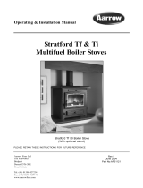
Minimum Clearance
from Inflammable
Materials
Minimum
Required
Clearance
for
Operation
A 18" 450mm 12" 300mm
B 16" 400mm 12" 300mm
C 12" 300mm N/A
D 16" 400mm 2" 50mm
E 16" 400mm 6" 150mm
A
B
D
C
E
F
1
2/3
2/3
1/3 2/3
Installation
Do not be tempted to fit the stove into an unsuitable fireplace. Beyond the requirements of the building regulations
and access to facilitate servicing the stove, providing a setting which will compliment the Harmony is not a luxury,
it is the practicality of making the most of an investment. A good builder will be able to transform even the most
utilitarian of fireplaces, whether altering its proportions to those of the “Golden Mean” ideal, exposing a wooden
lintel, stone or simply removing superfluous detailing for comparatively small costs, and the result will be a pleasure
for many years.
Minimum installation clearances
Decorative plinth for Harmony 5
F = Decorative Hearth Plate
Supplied as standard with Harmony 5
The measurements are for advice only. In all
installations surrounding inflammable materials
must not exceed 80oC. The stove must always stand
perfectly level and have sufficient space allowed for
service work.
F

© Euroheat Distributors (H.B.S) Ltd. 2000 Instructions Part number IN10111 Edition C
12
5. Some Advice and Instructions
1) Question:
What happens if the chimney flue descends to a lower
floor (the cellar, for example)?
Answer:
The combustion gases involve some DEAD WEIGHT
when mixed with a pocket of cold air. This will have a
considerable detrimental effect on the drawing power
of the chimney.
Remedy:
It is necessary to block the chimney with a metal sheet
or concrete, etc. a few centimetres below the joint of
the connecting pipe. Sufficient depth for a debris trap
should be provided.
2) Question:
What happens if you wish to connect an appliance to a
chimney flue, to which another stove is already
connected?
Answer:
This is prohibited under the U.K. building regulations
and should not be allowed.
3) Question:
What happens when a chimney flue is excessively large?
Answer:
The combustion gases leaving the stove through a given
section expand suddenly, cool down and lose all
ascending force. The drawing power is, therefore, very
weak or non existent.
Remedy:
The chimney must be lined to give it a more suitable
size.
4) Question:
What happens if the flue draught is to low?
Answer:
The stove will be difficult to light, responding only slowly
to the demands of increased output and unable to reach
its full heating output.
Remedy:
a) Ensure there is enough free air to the stove.
b) The flue is of a suitable size and is not obstructed.
c) Consult installation instructions.
5) Question:
What happens if there is to much flue draught?
Answer:
This can seriously damage the stove. An environment
can be created akin to a Blacksmiths forge within the
body of the stove. Early signs of this is an uncontrolable
fire, the glass crazing on the inside. Later signs are burnt,
bent and buckelled cast iron internal stove parts.
Remedy:
Ensure the stove is installed and commissioned as per
the installation instructions so that a flue draught test is
carried out prior to use. A flue draught stabaliser can be
fitted to the flue and a flue draught reading again taken.
6) Question:
What do you do when a customer insists that the
appliance be fitted in poor conditions?
Answer:
Poor conditions can only arise mainly due to the chimney.
In this case the customer must be convinced that
modifications are necessary. It is always preferable to
abstain from taking action which will result in poor
installation and so poor stove operation.
7) Question:
Why must connecting flue pipes be inclined upwards?
Answer:
a) to prevent the gas from stagnating in the flue pipe;
b) to prevent condensation by cooling off the gas;
c) to prevent the sooting up of the pipes and the stove
itself.
8) Question:
What should the degree of incline be?
Answer:
Given that the ideal chimney is vertical, angles should
be avoided as far as possible and the incline should be as
close to vertical as is practicable. The further away from
the chimney the stove is placed, i.e., the more flue pipe
required, the greater their incline should be.

© Euroheat Distributors (H.B.S) Ltd. 2000 Instructions Part number IN10111 Edition C
13
To correctly commission the fully installed stove a flue draught measurement gauge will be required. This should
be sufficiently accurate to measure the negative pressure produced in the chimney system. If a flue stabilizer is
fitted it should then be set in accordance with the graphic below, with the stove at maximum setting.
Commissioning
1. Adjusting thermostat setting
1mm
Thermostat
adjustment
screw
The cold setting of the thermostat must be checked before the
stove is operated for the first time.
With the stove cold the gap between the inside left of the
thermostat disc and the cast iron body of the stove should be
1mm. at normal room temperature.
Note the thermostat disc is designed to close at a predetermined
angle.
firing rate
0.04
0.02
0.06
millimetres
inches
firing rate
2. Flue draught measurement
Flue draught measured
with the air wash vent
fully open and all other
air supplies to the fire
closed.
Euroheat can supply flue
measurement gauges
order number MS026.
Note this is not a water
gauge used to measure
gas pressure.
.02
.01
.03
.04
.05
.06
.07
.08
.09
.05
.1
.2
.3
.4
.5
.6
.7
.8
.9
1.0

© Euroheat Distributors (H.B.S) Ltd. 2000 Instructions Part number IN10111 Edition C
14
Flue Draught Measurement. cont
The negative pressure created within the combustion chamber of the stove must be measured using a test hole
drilled into the flue, as close to the stove as possible and before any draught stabilizer that may be fitted to the flue.
To ensure a constant air inlet size the readings should be taken with both the grate and the thermostatically controlled
air inlet to the stove shut, and the secondary air-wash inlet fully open.
A reading should be taken before the stove is lit to identify any possible problems which may be caused by air being
drawn down the flue by other heating appliances fitted with a flue, extraction fans, etc.. These should be dealt with
before lighting the stove.
Once lit, the stove and flue should be allowed to warm thoroughly before letting the fire burn at a low setting.
While taking the flue draught reading, all air entries to the combustion chamber of the stove should be closed
except the secondary air-wash shutter, which should be fully open. The draught measurement should read
approximately 0.5mm gg.
The stove should now be made to burn at its maximum output and another draught measurement taken, again
closing all air supplies to the stove other than the secondary air-wash shutter. The draught reading when the burner
is operating at its maximum setting should be approximately 1.5mm. gg.
A flue draught which is too low will result in the stove being difficult to light, responding only slowly to demands
for increased output and unable to reach its full heating output.
Flue draught which is too high will make control of the fire difficult, and makes it possible to over fire the stove,
which can seriously damage it. In this instance a flue draught stabaliser may need to be fitted.
The installation manual should be consulted if the flue draught pressure readings are incorrect.
3. Operation and Lighting
The customer is to be advised about the operation and lighting procedures, use of the tools and general maintenance
of the stove.
4. Warranty
The warranty registration form should be completed and the user advised to return it fully completed to Euroheat
for registration.
5. Instructions
All instructions are to be left with the user.
/