WarmlyYours TCT120-KIT-ST-3.7W-150 Installation guide
- Category
- Motorcycle Accessories
- Type
- Installation guide

Free Design Service • 24/7 Installation Support • No Nonsense™ Warranty •(800) 875-5285 • www.WarmlyYours.com
TempZone™ Floor Heating Cable
Installation Instructions


1 ProductInformationandSpecications ................................................................................................ 1
2 Before You Begin ................................................................................................................................... 2
3 PlanningtheInstallation ....................................................................................................................... 4
4 ElectricalConsiderations ....................................................................................................................... 6
5 InstallationandOperation .................................................................................................................... 9
6 Testing ................................................................................................................................................... 19
7 OperatingTips ....................................................................................................................................... 21
8 Troubleshooting .................................................................................................................................... 22
9 Addenda ................................................................................................................................................ 26
10 Warranty Information ............................................................................................................................ 30
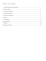
Table of Contents

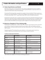
1.1 Product Specications and Details
Radiantoorheatingsystemsareuniquelydesignedforuseasprimaryorsupplementalheatsourcesinresidentialor
lightcommercialapplicationsforuseundertile,stone,hardwood,engineeredhardwood,carpet(verifyinstallationisin
compliancewithlocalelectricalcode),andlaminateooring.
TheTempZone™FloorHeatingCableiscomposedofatwin-conductorcableandacoldleadof15feetforconnectiontoa
powersource.Theheatingcabledelivers3.7watts/linearfoot.Wattagepersquarefootdependsontheinstallation.Referto
the“ProductSelectionGuide--120V”or“ProductSelectionGuide--240V”insection9foradditionalinformation.
TheTempZone™heatingcableconsistsofacopperalloyresistance-heatingelementinsulatedwithauoropolymerhaving
highdielectricstrengthandtheabilitytowithstandhightemperaturestoensuresafety.Thecoreissurroundedbyacopper
metalscreening,whichprovidesadditionalmechanicalstrengthandagroundpath.Afoilshieldsurroundsthecopper
groundtovirtuallyeliminateEMF.Anouteruoropolymerjacketstrengthensthecableandprotectsagainstcorrosion.
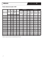
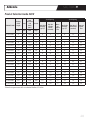
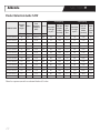
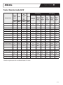
1.2 Selection of TempZone™ Floor Heating Cable
TheTempZone™FloorHeatingCableisavailableineither120Vor240Vandarangeoflengthstomeettherequirements
ofeachinstallation.Todeterminetheappropriateproductforyourinstallation,refertothe“InstallationandSpacing
Recommendations”chartbelow,andthenconsulteitherthe“ProductSelectionGuide--120V”or“ProductSelectionGuide--
240V”insection9.
WarmlyYoursTempZone™FloorHeatingCablecanbeinstalledat3-or4-inchintervalstomeettheneedsofany
installation.Todeterminewhichspacingworksbestforyourinstallation,considerthefollowing:
Installation and Spacing Recommendations
3-inch Spacing 4-inch Spacing
Wattage
(dependsoncablelength)
15watts/sq.ft. 11watts/sq.ft.
Heating Type Primaryorsupplemental Supplemental
SuboorType Concreteandwood Wood(andothernon-concretesurfaces)
Flooring Type Tile,stone,laminate,carpet* Hardwood,engineeredwood,laminate,carpet*
WetAreas Bathrooms,showers N/A
Climate Colderandwarmerclimates Warmerclimates
Recommendeduses
Olderhomeswhereinsulationmaynot
be optimal
Newhomeswithoptimalinsulationvalues
Coverage
120V:upto120sq.ft.
240V:upto240sq.ft.
120V:upto160sq.ft.
240V:upto325sq.ft.
* Note: Cable must be embedded in a 3/8 inch layer of self-leveling underlayment.
Product Information and Specications
SECTION 1
1

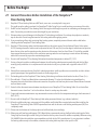
2.1 General Precautions Before Installation of the TempZone™
Floor Heating Cable
2.1.1 TempZone™FloorHeatingCablemustNOTtouch,crossover,oroverlapitselfatanypoint.
Thiscouldcausethecabletooverheat.UseTempZone™CableFixingStripstoavoidbunchingorcrossoverofthecable.
2.1.2 DoNOTcuttheTempZone™FloorHeatingCable.Alteringthecablelengthmayresultinoverheatinganddamagetothe
cable.Ensurethatyouorderthecorrectcablelengthforyourinstallation.
2.1.3 TakeprecautionstoavoiddamagetotheTempZone™cableduringinstallation.Donotdropsharpobjectsorcarelessly
steponthecable.Donotbangthetrowelontheheatingcablewhileapplyingmortar.
2.1.4 Ifyouarereplacingaoorwithanexistingoorheatingsystem,completelyremoveoldmatsand/orcablebefore
installingnewtheTempZone™FloorHeatingCable.
2.1.5 TempZone™oorheatingcablesshouldbeseparatedfromotherheatsources.PertheNationalElectricCode,section
424.39,heatingelementsofcablesmustbeseparatedatleast200mm(8in)fromtheedgeofoutletboxesandjunction
boxesthataretobeusedformountingsurfaceluminaires.Aclearanceofnotlessthan50mm(2in)shallbeprovided
fromrecessedluminairesandtheirtrims,ventilationopeningsandothersuchopeningsinroomsurfaces.Noheating
cableshallbecoveredbyanysurface-mountedequipment.
2.1.6 DonotinstallTempZone™FloorHeatingCablewhentheambienttemperatureisbelow5ºF(-15ºC).
2.1.7 Ifusingathermalinsulationunderlaymentbetweentheself-levelingunderlayment-encasedcableandthenaloor
covering(verifyinstallationisincompliancewithlocalelectricalcode),useaproductwithatypicalR-valueof0.027
orless.
2.1.8 WarmlyYoursrecommendsusingCeraZorb®underlaymentwheninstallingcableoveraconcreteoororslabtoallowa
greaterpercentageofheatgeneratedtotransfertotheooringsurface.
2.1.9 ThebendingradiusoftheTempZone™FloorHeatingCableduringinstallationshouldnotbelessthan25mm(1in).
2.1.10Thecoldleadis15feetlong.WarmlyYoursrecommendsallowing12inchesofcoldleadwiretoextendfromthe
thermostatboxtofacilitateeasierthermostatconnection.Anyexcesscoldleadmaybetrimmed.Pleasefollowallnational
andlocalelectriccodes.
2.1.11 CentertheoorthermostatsensorbetweentwoadjacentrunsofTempZone™FloorHeatingCable.Donotlocateoor
thermostatsensorcloserthan1inchtothecableorallowittooverlapanyothercable.
2.1.12 Carpetandlaminatemanufacturersmayrecommendamaximumlimitforthetemperaturesettingonthethermostatof
86ºF(30ºC).
2.1.13 DonotinstalltheTempZone™FloorHeatingCableunderpermanentxtures(e.g.cabinets,bathtubs).
2.1.14 Allowforasufcientdryingorcuringperiodofthesuboorandnishedoorcoveringbeforeandafterinstallingthe
TempZone™FloorHeatingCable.DoNOToperateoorheatuntilthethinsetorself-levelingunderlayment(SLU)has
completely cured.
2.1.15Pleasenotethethicknessofthefactoryspliceandcoldleadandplanaccordingly.
2.1.16Whenusingself-levelingunderlayment(SLU),WarmlyYoursrecommendsprimingtheoorbeforeattachingtheCable
FixingStripsandsecuringthecable.Doingsowillensurethattheprimercoversthesuboorcompletely.Wheneverusing
SLU,ALWAYSfollowtheinstallationrecommendationssetforthbytheSLU’smanufacturer.Itisveryimportanttoadhere
theheatingcablesecurelytothesuboor,otherwisetheheatingcablemayoattothetopoftheSLU.
Before You Begin
SECTION 2
2

Before You Begin
SECTION 2
3
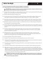
2.2 Important Electrical Precautions Before Installation
IMPORTANT: Where required, all electrical connections should be performed by a licensed, certied electrician in
accordance with local and national electrical code requirements.
2.2.1TempZone™FloorHeatingCablehasanearth-groundingbraid(metalsheath).Theearth-groundingbraidshouldbeproperly
grounded.Thecorewiresshouldbeconnectedtothemainpowersupply.
2.2.2Verifythatcablevoltagematchesthevoltageofcircuit.
2.2.3ChecktheohmsresistanceoftheTempZone™FloorHeatingCablebefore,during,andafterinstallation.Resistancevalue
shouldmatchthevaluegivenonthelabelattachedtothecable.Atoleranceof-5/+10%at20ºC(68ºF)isallowed.
2.2.4Localelectricalcodesmayrequirethelow-voltagesensorwiretobeinstalledinconduit.Ifthisisrequired,donotinstallthe
low-voltagesensorleadintheconduitcontainingthecoldleads.Provideaseparateconduitforthelow-voltagesensorwire.
2.2.5WarmlyYoursstronglyrecommendsconnectingtheCircuitCheck™devicetowarnofaccidentaldamagetotheTempZone™
FloorHeatingCableorleadwiresduringinstallation.
2.2.6TempZone™FloorHeatingCableshouldbeconnectedtoaListedClass–AGroundFaultCircuitInterrupter(GFCI).Ifusingone
ofourprogrammableornonprogrammableListedthermostatsthatincludeabuilt-inGFCI,thenaseparateClass–AGFCIisnot
required.
2.2.7IftheGFCIistrippedduringnormaloperationandcannotbereset,theremaybeafaultinthecable.DoNOTattemptto
re-energizetheTempZone™FloorHeatingCable.DoNOTbypasstheGFCIunderanycircumstances.Contactaqualied
electricianorWarmlyYoursforassistance.
2.2.8Indicatewhichbranchcircuitsorcircuitbreakerssupplythepowertotheoorheatingcableinaconvenientlocation
(e.g.tapedtothecircuitbreakerbox)forreferencebytheelectricalinspectororhomeowner.RetaintheULlabelsforeach
TempZone™FloorHeatingCable.LeaveoneULlabelattachedtotheoorheatingcable.
2.2.9UseonlyListedconduit,ttings,andothercomponents.
2.2.10TempZone™FloorHeatingCableshallnotextendbeyondtheroomorareainwhichitoriginates.
2.2.11TheTempZone™FloorHeatingCableshouldonlybeinstalledbyqualiedpersonnelwhoarefamiliarwiththeconstruction
andoperationoftheTempZone™FloorHeatingCableandtherisksinvolved.
2.2.12TheinstallationoftheTempZone™FloorHeatingCableshallbeinaccordancewithallmanufacturer’sinstructionsandlocal
andnationalcodes.
2.2.13InCanada,theinstallationshallbemadeaccordingtotheprovisionsofsection62oftheCanadianElectricalCode,Part1.
2.2.14Whenusedinwetlocations,theinstallationshallbeinaccordancewiththeNationalElectricalCode(NEC),NFPA-70and
CAN/CSA-C22.1,CanadianElectricalCode(CEC),PartI.FinalapprovaloftheinstallationistobedeterminedbytheAuthority
HavingJurisdiction(AHJ).TheULListingforthisproductdoesnotcoveruseinwetlocationsintheUnitedStates.Installations
shallbeinaccordancewiththeNationalElectricCode,NFPA70andanyotherapplicablejurisdictionalcodesandnal
acceptanceistobemadebytheAuthorityHavingJurisdiction(AHJ).
WARNING : Risk of electric shock and re. Damage to supply conductor insulation may occur if conductors are
routed less than 2 in. (51 mm) from this heating product. Refer to installation instructions for recommended
means of routing supply conductors.

Planning the Installation
SECTION 3
4
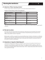
3.1 Selection of Floor Covering material
TheoorcoveringmaterialsusedwiththisproductmustnotexceedathermalinsulationR-valueof1.
Examples of Common R-values for Floor Covering Materials*
Floor Covering Material Thickness (inches) R-value
Carpet 3/8 1.0
Tile(ceramic,mosaic) 1/4 0.15
Laminate 3/8 0.675
Plywood ½ 0.63
Naturalstone(granite,
limestone,marble,sandstone)
1 0.38 to 0.114
Wood 3/4 0.80maximum
*These values are provided for general reference purposes only. Consult the oor covering manufacturer for product-specic
information.
3.2 Thermal Insulation
TheinsulationlevelsoftheoorwillaffectboththeperformanceandoperatingcostsoftheTempZone™oorheating
system.Thermalinsulationreectstheheatupwardsintotheoortileinsteadofallowingheattopenetrateintothe
suboor,keepingtheoorwarmerforalongertime.
Whenthecableisinstalledonaconcreteslab,werecommendaddingalayerofinsulationtotheslabpriortoinstallingthe
TempZone™FloorHeatingCable.Addinginsulationontopoftheconcreteslabandbeneathanyoorheatingsystemwill
allowagreaterpercentageofheatgeneratedtotransfertotheooringsurface.WarmlyYoursrecommendsusing5mm
thickCeraZorb®syntheticcorkunderlayment.
3.3 Calculation of Length of Cable Required
Todeterminetheappropriatecablelengthfortheinstallation,measuretheareatobeheatedandcalculatetheareain
squarefeet.Donotincludetheareacoveredbyxedobjects,suchasappliances,bathtubs,cabinets,etc.Refertothe
“InstallationandSpacingRecommendations”chartinsection1.2todeterminetherecommendedwattdensitypersquare
footforthetypeofinstallation.Referto“ProductSelectionGuide--120V”or“ProductSelectionGuide--240V”insection9to
selectappropriatecablelength.

Planning the Installation
SECTION 3
5
3.4 Calculation of On-Center Spacing (OC)
InordertottheTempZone™FloorHeatingCableproperlyinthedesignatedspace,itisnecessarytodeterminethe
spacingbetweenthecables.Thisiscalledon-centerspacingorOC.Refertoeitherthe“ProductSelectionGuide--120V”or
“ProductSelectionGuide--240V”insection9todetermineappropriatespacingfortheinstallation.
Combinecablelengthsifmorethanoneisneededfortheinstallation.OncetheOCspacinghasbeencalculatedandthe
correctlengthofcablefortheareatobeheatedisobtained,installationoftheoorheatingcablecanbegin.Theformula
assumesthat3-inchspacingwillbeusedbetweentheheatingcableandwallsorxedobjects,andfullOCspacing
betweencableruns.Tomakecableplacementeasier,makeameasuringtemplateoutofcardboardinthewidthoftheOC
spacinglessthethicknessofthecable.Placethetemplatealongtothecablerunjustcompletedtodeterminewherethe
nextrunofcableshouldbepositioned.
IMPORTANT: To avoid overheating, OC spacing should not be less than 3 inches and area loading should not
exceed 15 watts/square foot.
IMPORTANT: Do not order more cable than necessary as cable cannot be shortened.
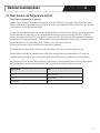
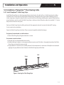
3.7W Cable vs 3W Cable Wattage Yields
Current
3 W Cable
New
3.7 W Cable
Membrane Type
(number of studs)
Watts/linear ft 3 3.7
Watts/ft2at2.5” 14.4 17.76* Prodeso(2)
Watts/ft2at3” 12 14.8 CableFixingStrip(3)
Watts/ft2at3.5” 10.3 12.7 DITRA-HEAT(2)
Watts/ft2at3.75” 9.6 11.84 Prodeso(3)
Watts/ft2at4” 8.7 11.1 CableFixingStrip(4)
Watts/ft2at4.75” 7.6 9.3 DITRA-HEAT(3)
Watts/ft2at5” 7.2 8.9 CableFixingStrip(5)&Prodeso(4)
Wire diameter variable 4.37
DITRA-HEAT:1.75”
Prodesospacing:1.25”
Strips:1”
*Notrecommendedasitexceedsthe15wattpersquarefootlimitsetbytheNationalElectricCode.

Electrical Considerations
SECTION 4
6
4.1 Floor Sensors and Temperature Control
Floor Sensor (not required for all systems)
SystemsusingaSmartstat™ProgrammableThermostatorEasystat™Thermostatmayrequirealow-voltageoorsensor.
Carpetorlaminateooringmanufacturersmayrequiretheuseofalow-voltagesensorwiththeiroorcovering.Checkwith
themanufacturerforspecicrecommendations.
Thissensorisembeddedintheoorandmonitorstheoortemperature.Checktheohmsreadingofthesensorwirebefore
andafterinstallationtomakesureithasnotchanged.Mostsensorwireshaveanohmsreadingof8,000to20,000Ω,
andyourohmmetermusthavea20kΩsettingforthismeasurement.Theoorsensorshouldbecenteredinbetweentwo
resistancewires,leavingapproximately1.5inchesoneithersideandextendingabout6inchesintotheheatedarea.Avoid
placingthesensorinanareaaffectedbyadraft,aradiatororotherheatsource,orthesun.
Asecond,backupsensormaybeinstalledandcanbepurchasedseparately.
Thesensorcableshouldberoutedtothethermostatandinstalledonthewallatasuitableoperatingheight.
Donotallowanyothercabletooverlapthesensorcable.Whenheatinglaminateandcarpetedoors(U.S.only),the
maximumtemperaturesettinglimitonthermostatshouldnotexceedtheooringmanufacturer’srecommendations.
RouteTempZone™FloorHeatingCableleadwirestoajunctionboxortothethermostat.Neverconnecttheoorheating
cabletoothercables.Thethermostatandthecableleadwiresmustbeconnectedinparallel--notinseries.
Type of Wire Color
120V YellowandBlack
240V RedandBlack
FloorSensor Black

Electrical Considerations
SECTION 4
7
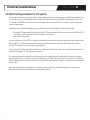
4.2 Electrical Requirements for the System
Whererequired,allelectricalworkfortheoorheatingcableinstallationmustbedonebyaqualied,licensedelectrician
inaccordancewithlocalbuildingandelectricalcodesandtheNationalElectricalCode(NEC),especiallyArticle424,Part
IXoftheNEC,ANSI/NFPA70andSection62oftheCanadianElectricalCode(CEC),PartI,aswellasanyotherapplicable
statutoryrequirements.
WarmlyYoursrecommendsthefollowingcontrolsandaccessoriesfortheTempZone™FloorHeatingCable:
•SmartStat™ProgrammableThermostatorEasyStat™Thermostat.BothoftheseunitsfeatureaListedClass-AGFCI
andaoorsensortoregulatetheactualtemperatureoftheoor
•Non-GFCIcircuitbreaker
Inmostinstallations,aClass-AGFCIisrequiredbynationalandlocalcodesforprotectionagainstgroundleakagecurrents.
AClass-AGFCIisincludedwiththeSmartstat™andEasystat™thermostats.IfnotusingaWarmlyYoursthermostat,a
Class-AGFCIthermostatorcircuitbreakermaybeneeded.
TheTempZone™FloorHeatingCableshouldbeconnectedtoanon-GFCIcircuitbreakerforcompletedisconnectiononall
poleswithminimum0.12inchdisconnectiondistance.
Thethermostatshouldbeinstalledinadouble-gangboxwithasingle-gangmudringushwiththewallataheightof
approximately5feetoreyelevelforeasyaccessandoperation.TheoorsensorcableandtheTempZone™FloorHeating
CablecoldleadsshallberoutedtothethermostatinseparateULListedconduitsifconduitisrequiredbylocalandnational
electriccodes.
Iftheoorheatingcableloadexceedsthe15-ampthermostatpowerrating,consultWarmlyYoursforinformationon
alternativesolutionsusingmasterthermostatsandpowermodules.

Electrical Considerations
SECTION 4
8
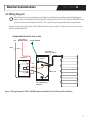
4.3 Wiring Diagram
Note: All electrical work must be done by a qualied, licensed electrician in accordance with local building and
electrical codes, and the National Electrical Code (NEC), especially Article 424, Part IX of the NEC, ANSI/NFPA 70 and
Section 62 of the Canadian Electrical Code (CEC), Part I, as well as any other applicable statutory requirements.
Exampleoftypicalwiringdiagramfor120Vor240VinstallationsisgiveninFigure1.Refertotheinstructionsthatcame
withyourspecicthermostat.
Figure 1. Wiring Diagram for 120V or 240V WarmlyYours TempZone™ Floor Heating Cable Installation
HOT
FROM POWER SOURCE 120V or 240V
HOT (240V) or
NEUTRAL (120V)
HOUSE GROUND
Red (240V) or
Yellow (120V) Wires
Double-Gang Box
with a Single-Gang
Mud Ring
Red
Black
Red
Copper
Ground
Black
Black Lead
THERMOSTAT
Load
S
L2 (N)
L1 (L)
BRAIDED GROUND SHEATH
COLD LEAD
BLACK WIRE
RED 240V
or
YELLOW 120V

Installation and Operation
SECTION 5
9
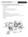
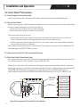
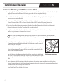
5.1 Recommended Equipment and Items for Installation
The following equipment and items are recommended for installation of the WarmlyYours TempZone™
Floor Heating Cable :
•Ohmmeter(ormultimeter)
•CircuitCheck™
•Hotgluegun(ifusinghotgluetosecuretheCableFixingStrips)
•Industrial-gradehotglue(ifusinghotgluetosecuretheCableFixingStrips)
•Chiselorroutertocreateagrooveforthespliceinthesuboor
• Hammer
•Screwdriver
•Protectivewallplate
• Duct tape or high temperature tape
•Staples,nails,adhesiveor1⁄2inchscrewstoattachtheCableFixingStripstothesuboor
•Class-AGroundFaultCircuitInterrupter(ifnotusingaWarmlyYoursthermostat)
•Double-gangelectricalboxwithasingle-gangmudring/deviceplateforeachthermostatorpowermodule
•Listedelectricalconduit(tobeprovidedbyinstaller)
•Permanentmarker
•Tapemeasure
•Utilityscissors
Hot glue gun
SmartPlan™
Tape
Tape measure
Ohmmeter
Electrical box
Circuit Check™
Screwdriver
Utility knife
Marker
Scissors
Hammer

Installation and Operation
SECTION 5
10
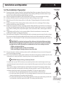
5.2 Pre-Installation Preparation
5.2.1Documenttheplan.FollowaSmartPlan™obtainedfromWarmlyYoursorprepareaoorplanofthearea
tobeheated.Usingaoorplan,withtheTempZone™FloorHeatingCablelayoutmarked,makesiteasyto
tracetheheatingcableroutingfortroubleshootingifnecessary.
5.2.2SelecttheappropriateTempZone™FloorHeatingCable,ensuringitisthecorrectlengthandvoltage.
5.2.3Identifyasuitablelocationforinstallingthethermostatandlow-voltagesensorifused.
5.2.4Markthelayoutoftheoorheatingcableontheoorplan.Takingphotographsoftheareamayalsobe
helpful.
5.2.5InspecttheTempZone™FloorHeatingCablevisuallyandensurethatitisnotdamaged.Checkvoltage,
wattage,andresistancevaluesonthelabel.
5.2.6Propersurfacepreparationofoorisextremelyimportant.Makeabsolutelysurethattherearenoobjectson
theoorthatmightdamagetheTempZone™FloorHeatingCable.Sweeptheoortoensureitiscompletely
clearofdebris,includingnails,sharpmetallicobjects,wood,constructiondebris,anddamagedordefective
cables.
5.2.7Ifapplicable,installCeraZorb®ontheconcretesuboor.Followthemanufacturer’sinstructionswhen
installingtheCeraZorb®insulatingunderlayment.
5.2.8CheckresistanceofTempZone™FloorHeatingCablewithanohmmeteruponremovingitfromthepackage.
Theresistancevalueoftheheatingcableshouldmatchthevalueonthelabelattachedtothecablewitha
toleranceof-5/+10%allowedat20ºC(68ºF).Recordtheresistancevalueonthewarrantycardinsection10.
IMPORTANT:The electrical resistance of the cable must be checked before you begin
and monitored throughout the installation process to ensure there has been no damage
causing shorts or breaks. WarmlyYours recommends at least three readings be taken:
1. Before starting installation
2. After securing the cable in place on the suboor
3. After installing the ooring surface on top of the cable
5.2.9Usinganohmmeter,checktheinsulationresistanceofthecablebetweenthecorewiresandtotheground
wire.Itshouldalwaysreadinnity.
5.2.10UseaCircuitCheck™deviceduringcableinstallation.Thesedeviceswillprovideanaudiblealarmifthewire
isdamagedorcutduringinstallation.Acontinuitycheckerisnotacceptableforthesetests
IMPORTANT: Beware of Using a Continuity Checker!
Forcablesthathaveover200Ωresistance,somecontinuitycheckersdonotsendenoughcurrenttoget
completelythroughthewireandemitthenoiseorlightthatafrmspropercontinuity.Pleaseuseadigital
ohmmeter.
Three(3)ohmreadingsshouldbetakenforeachWarmlyYoursTempZone™FloorHeatingCableateach
stageoftheinstallationandrecordedinthetableonthewarrantycardinsection10.RefertoFigure2for
instructionsabouthowtoattachtheohmmeterorPowerMan™totakeeachtypeofreading.
1.CoretoCore:Thisisthereadingbetweenthetwoinnerconductorsontheleadwires.
2.CoretoGround,Yellow/RedLead:Thisisthereadingbetweentheinnercoreandtheouterground
sheathontheleadwire.Thisreadingshouldbeinnity.
3.CoretoGround,BlackLead:Thisisthereadingbetweentheinnercoreandtheoutergroundsheath
ontheleadwireatthenishpointofthecable.Thisreadingshouldbeinnity.
Figure 2.
Attachment points
for ohm readings
Ground Braid
Ground Wire
Yellow
or Red
Ground
Ground
Yellow
or Red
Black
Black
Core to Core
Yellow
or Red
Ground
Ground
Yellow
or Red
Black
Black
Core to Sheath
Yellow
or Red
Ground
Ground
Yellow
or Red
Black
Black
Core to Sheath
Yellow
or Red
Ground
Ground
Yellow
or Red
Black
Black
Core to Core
Yellow
or Red
Ground
Ground
Yellow
or Red
Black
Black
Core to Sheath
Yellow
or Red
Ground
Ground
Yellow
or Red
Black
Black
Core to Sheath

Free Design Service • 24/7 Installation Support • No Nonsense™ Warranty •(800) 875-5285 • www.WarmlyYours.com
SHEATH
CORE
CORE
Black Inner Lead
Yellow (120V)
or Red (240V)
Inner Lead
Copper
Ground Sheath
ON OFF
BLACK
GREEN
RED
Wire Construction
Circuit Check Installation
10061
Rev 1/11
BRAIDED GROUND SHEATH
COLD LEAD
BLACK WIRE
RED 240V
or
YELLOW 120V
Installation and Operation
SECTION 5
5.3 Circuit Check™ Instructions
5.3.1 Install TempZone™ Floor Heating Cable
InstalltheoorheatingcableinaccordancewiththedesignlayoutandinstructionsprovidedbyWarmlyYours.
5.3.2 Test the Circuit Check™
Beforeconnectinganywires,installthebatteriesinthedeviceandturnitonandofftotestthealarm.Afterconrmingthat
thealarmisingoodworkingorder,connectthewiresasfollows:
•Connectblackinnerconductorcorewiretotheblackterminal
•Connectsecondinnerconductorcorewiretotheredterminal
Therearetwowaysofdoingthenextstep:
1.Splitthegroundsheathintwo.Connectonehalfofthegroundsheathtothegreenterminal,turnontheCircuit
Check™,andtouchtheotherhalfofthegroundsheathtooneoftheinnerconductorwires.
2.Installtheentiregroundintothegreenterminal.Turnonunitanduseapaperclipasabridgebetweentheground
wireandeitheroneoftheinnerconductors.
Eithermethodshouldactivatethealarm.IftheCircuitCheck™doesnotpassallthesetests,pleasecallWarmlyYours24/7
InstallationSupportat(800)875-5285forassistance.
5.3.3 Activate the Circuit Check™ and Proceed to Install Flooring
5.3.4 If the Circuit Check™ Alarm Sounds, Stop!
Ifthealarmsounds,thereisashortinthecircuitorbreakinthesystem.Refertothetroubleshootingguideinsection8of
thisinstallationmanualorcall24/7InstallationSupportat(800)875-5285.
WarmlyYourscanshipasplicekittorepairtheshort.Alternatively,thewiremayberepairedbyanelectrician.Pleasesee
thewirerepairdocuments“InstructionsforTwinConductorTempZone™Repair”atwww.warmlyyours.com/publications/TZ-
TWIN-REPAIR-30027-B/downloadand“TempZone™Cut&TurnTwinConductorSolderMethodWireRepair”at
www.warmlyyours.com/publications/TZ-TWIN-SOLDER-REPAIR-30028-A/downloadorcallus24/7at(800)875-5285.
13
Figure 5. How to connect the Circuit Check™ for installation

Installation and Operation
SECTION 5
5.4 Installation of TempZone™ Floor Heating Cable
5.4.1 Install TempZone™ Cable Fixing Strips
InstallCableFixingStripsinadirectionperpendiculartothedirectionthecablewillrun.CableFixingStripsshouldbe
installedatleast3inchesfromthewallperimeter.WarmlyYoursrecommendssecuringthecabletotheoorevery20
inchesusingtapeorhotgluetokeepthecableinpositionuntiltheself-levelingunderlaymentisapplied.Whenworking
aroundcabinetsorvanities,installtheCableFixingStripsatadistancethatwillallowthecabletobeinstalled1-1/2inches
awayfromthecabinetorvanitybase.
EachrowofCableFixingStripsshouldbepositionedattheappropriateintervalstoensurethedesiredOCspacing
(3or4inches)fortheinstallation.
SecuretheCableFixingStripstotheoor.Thereareseveralacceptablemethodsfordoingso.
For plywood, cement board, or similar surfaces:
•SecureCableFixingStripwithgalvanizednailsorscrews.
For concrete or similar surfaces:
•Concretenailsarerecommendedforbestresults.
•Double-sidedtape,hotglue,orastrongsprayadhesivemaybeusediftheooristhoroughlycleanedandtheCable
FixingStripsarecleanedtoremoveanyoils.
•Ifsprayadhesiveisused,besuretocarefullyfollowallofthemanufacturer’sinstructions.WarmlyYoursrecommends
applyingthesprayadhesivetoboththebackoftheCableFixingStripandtheoor.
Nail
Screw
14
Figure 6. Securing the Cable Fixing Strips

Installation and Operation
SECTION 5
5.4.2 Install the TempZone™ Floor Heating Cable
1.Begininstallingtheheatingcablefromthethermostatorjunctionbox.Followthepatternmarkedontheoorplan(if
supplied).Pleasenotethethicknessofthefactoryspliceandcoldleadandplanaccordingly.
2.Unwindthecablefromthespool.SecureitusingtheTempZone™CableFixingStrips.Avoidbunchingthecableor
crossingoverotherpartsofthecable.
3.TheTempZone™FloorHeatingCableshouldbeinstalledinauniformly-spacedserpentinepattern.Refertoeither
“ProductSelectionGuide--120V”or“ProductSelectionGuide--240V”insection9forspacinginformation.
4.Takenoteofthecable’shalfwaypointmarkingindicatedonthecable.Thismarkshouldmatchthehalfwaypoint
indicatedonthecustomSmartPlan™suppliedwiththeorder(optional).
5.Routethepowerleadsfromtheoortothethermostatbox.Ifusingmultipleheatingcables,routethepowerleadsfrom
theoortoajunctionboxorthermostatboxinthewall.
NOTE: Leads should be protected at the point they leave the oor. Rigid metal conduit, intermediate metal
conduit, rigid nonmetallic conduit, electrical metallic tubing, or other means approved by local electrical codes
should be used.
6.Forinstallationsincludingathermostat,thelow-voltageoorsensorshouldbeplaced
inbetweentheloopscreatedbythecableandheldinplacewithasmallamountof
thinsetorhotglue.SeeFigure7.
Thesensorwirecannotcrossanyheatingcableorleadwire.Itmustextendatleast6
inchesintotheheatedarea.Thesensoranditswireshouldbecovereddirectlywith
thinsetorself-levelingunderlayment.
Thecoldleadwiresshouldbeplacedabovethesuboor,alongthesideoftheheated
areaatleast2inchesfromtheheatingwire.Securethecoldleadwireswithasuitable
tapeorhotgluebeforethethinsetorself-levelingunderlaymentisappliedoverthe
cables.
7.Useanohmmetercheckthecontinuity,insulationresistance,andresistancevaluesagainafterthecablehasbeen
installed.Comparethesepost-installationvalueswithpre-installationvaluestoensuretheyareconsistent.Recordpost-
installationvaluesonthewarrantycardinsection10.
AttachCircuitCheck™tocoldleadsatthistime.
Figure 7. Placement of the
oor temperature sensor
15

8.Applythinsetorself-levelingcompoundovertheheatingcableandsuboor.Acrylic,latex,orpolymer-modiedthinset
cementmaybeused.Ensurethatthematerialyouselectiscompatiblewiththeooringmaterial.Contacttheadhesive
manufacturerformoreinformationandcuringtimes.
Ensurethattherearenoairgapsduringapplicationofthinsetorself-levelingunderlayment(SLU).Makesurethe
heatingcable,factorysplices,andlow-voltagethermostatsensor(ifused)arecompletelyembeddedinthethinsetor
SLU.IfSLUisused,besuretouseanyprimerrequiredbythemanufacturer.
Asingle-ordouble-layermethodmaybeusedoveranysuboor(plywood,cementslab,concretebackerboard,or
mudbed).Thesemethodsaresuitableforanystoneortileoorcovering.Forcarpet(U.S.only),vinylorlaminateoor
coverings,WarmlyYoursrecommendscoveringtheoorheatingsystemwith3/8inchofself-levelingunderlayment
(totaldepth,whetherthesingle-ordouble-layerapplicationmethodisused)tocreateasmoothsurfaceforinstalling
thesetypesofooring.Followtheinstructionsappropriatetothetypeofoorcoveringtobeused.
CAUTION: Careless use of the trowel can damage the heating cable. Never drop or bang a trowel directly
on the cable.
5.4.3 Instructions for Installation in Wet Locations
1.InstallationshallbeinaccordancewiththeNationalElectricalCode,NFPA-70andCAN/CSA-C22.1,CanadianElectrical
code(CEC),Part1andthatnalacceptanceistobemadeintheeldbytheAuthorityHavingJurisdiction(AHJ).
2.WarmlyYoursrecommendsusingaseparateheatingcableforshowerareas.Note:TheULListingforthisproductdoes
notcoveruseinwetlocationsintheUnitedStates.InstallationsshallbeinaccordancewiththeNationalElectricCode,
NFPA70andanyotherapplicablejurisdictionalcodesandnalacceptanceistobemadebytheAuthorityHaving
Jurisdiction(AHJ).
3.Ifinsulationboardisbeingusedoveraslab,usesuitableglueorcement-basedadhesive,orthinsetmortartoadhereit
totheslab.Ifinstallinginawetlocation,ensuretheslopeofthemortarbedismaintainedsothatitdirectswatertothe
drainpipe.
Installation and Operation
SECTION 5
16

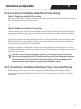
1.Weavethecablebackandforthacrosstheareaatthedesired
spacing.Maintainslighttensiononthecabletoensureitdoes
notpullloose.Ifdesired,usehotglueatintervalstohelp
ensureitstayssecure.NEVERspacethecableslessthan3”apart.
2.Markwherethefactorysplicewillbeplaced.Cutthemattingor
membraneandinsertsplice.Itmaybenecessarytosecurethe
splicetotheoorwithhotglue,adhesiveorthinset.
3.Embedtheheatingcablebetweenstuds,ataspacingof3
studs.Closerspacingmayresultinoverheatinganddamageto
buildingstructures.Awiderspacingmaynotprovidesufcient
powertowarmtheoor.
4.Cablemustbeturnedorau-shaped“jog”createdatevery10ft
(3m)ofcablerun.
5.Alwaysremembertoinstallthethermostatsensor(ifapplicable)
6”intoanopenloopoftheheatingwire.Cutintomembraneas
shown.
Installation and Operation
SECTION 5
17
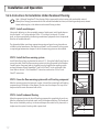
3” Spacing
RPM Mats
3.5” Spacing
Schluter Ditra-Heat (3.5”)
or Prodeso Mats (3.75”) Spacing

Installation and Operation
SECTION 5
5.4.4 Instructions for Installation Under Tile and Stone Flooring
Option 1: Single-layer method for tile and stone
Applyalayerof3/8inchlatex-modiedthinsetcementorself-levelingunderlayment(SLU)overtheheatingcable.Laythe
tileorstonedirectlyintothatlayerofthinsetcement.
OR
Option 2: Double-layer method for tile and stone
Embedtheheatingcableinaskimcoatoflatex-modiedthinsetorself-levelingunderlayment,completelycoveringthe
heatingelementandthesensorwire.Applyasecondlayerofthinsetandlaytilesasusual.Therecommendeddepthfor
bothlayersofthinsetorSLUis3/8inch.
Thesingle-layermethodisusedmostbyexperiencedinstallersinsmallapplicationswitheasyaccess.WarmlyYoursdoes
NOTrecommendthesingle-layermethodforinstallingmosaicsortilesofdifferentsizesorifyouhavenotinstalledan
electricradiantheatingsystemundertileorstonebefore.
WaitingPeriod:Regardlessofmethodused,installationofoorheatingcableundertileorstonerequires2to28days
forthelatex-modiedthinsetorself-levelingunderlaymenttocure.Followmanufacturerrecommendationsforcuretimes
applicabletoyourinstallation.
IMPORTANT: Do NOT turn on the WarmlyYours TempZone™ Floor Heating Cable system until after the
thinset or self-leveling underlayment (SLU) has fully cured. Doing so will result in damage to the system
and cause the thinset or SLU to become brittle. Failure of the thinset or SLU may cause damage to the
embedded cable. This type of damage is not covered by the WarmlyYours warranty.
5.4.5 Instructions for Installation Under Carpet, Vinyl, or Laminated Flooring
BeforeapplyingSLU,ensurethatthecableisrmlysecuredtothesuboortopreventitfromoatingtothetopof
theself-levelingunderlayment.AttachtheCircuitCheck™atthistime.Covercablewith3/8inchlayerofself-leveling
underlayment.
18

Installation and Operation
SECTION 5
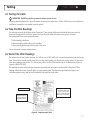
5.4.6 Instructions for Installation Under Hardwood Flooring
Note : Although TempZone™ Floor Heating Cable is approved for direct contact with combustible material,
WarmlyYours strongly recommends that the cable be embedded in thinset, self-leveling underlayment, cement-
based adhesive glue, or tile adhesive under wood ooring surfaces.
STEP 1: Install wood sleepers
Usingnails,adhesive,orotheracceptablemeansofattachment,installwoodsleepers
(stripsofwood1to2incheswideand3/8to1/2inchhigh)atintervals19inches
apart,ordistancespeciedbytheooringmanufacturer,perpendiculartotheplanned
directionofhardwoodboards.
Theplywoodsuboormustleaveappropriatespacingandgapsforanyplannedruns
ofcabletootherheatedareas.Thesleepersarexedinsuchamannerthattheycreate
arequiredgapbetweentwosleepersinwhichthewarmingsystemcanbeinstalled.
STEP 2: Install the oor warming system
InstallCableFixingStripsasdescribedinsection5.5.1.UsingtheCableFixingStripsto
securethecable,installtheoorwarmingsystemintothegapcreatedbythesleepers.
Carefullyreturnthepowerleadstothepowersupplyalongsidethewarmingsystem
andwoodsleepers.AttachPowerMan™andCircuitCheck™tothecoldleadsatthis
time.Refertosection5.3forPowerMan™instructionsandsection5.4forCircuit
Check™instructions.
STEP 3: Cover the oor warming system with self-leveling compound
Afterthewarmingsystemhasbeenputinplace,itshouldbecoveredwithself-leveling
compounduptotheheightofthesleepers.Donotcoverthesleepers.Thetopsofthe
sleepersshouldremainuncoveredandvisible.
STEP 4: Install hardwood ooring
Allowtheappropriatetimefortheself-levelingcompoundtocompletelydryandcure.
Afterthecompoundhasdriedandcured,installthehardwoodooring.Thehardwood
oorcanbeinstalledbynailingittothewoodsleepers.Becarefulnottoplacenailsor
staplesnearthesystem’sheatingcableorpowerlead.
19
Page is loading ...
Page is loading ...
Page is loading ...
Page is loading ...
Page is loading ...
Page is loading ...
Page is loading ...
Page is loading ...
Page is loading ...
Page is loading ...
Page is loading ...
Page is loading ...
Page is loading ...
-
 1
1
-
 2
2
-
 3
3
-
 4
4
-
 5
5
-
 6
6
-
 7
7
-
 8
8
-
 9
9
-
 10
10
-
 11
11
-
 12
12
-
 13
13
-
 14
14
-
 15
15
-
 16
16
-
 17
17
-
 18
18
-
 19
19
-
 20
20
-
 21
21
-
 22
22
-
 23
23
-
 24
24
-
 25
25
-
 26
26
-
 27
27
-
 28
28
-
 29
29
-
 30
30
-
 31
31
-
 32
32
-
 33
33


WarmlyYours TCT120-KIT-ST-3.7W-150 Installation guide
- Category
- Motorcycle Accessories
- Type
- Installation guide
Ask a question and I''ll find the answer in the document
Finding information in a document is now easier with AI
Related papers
-
WarmlyYours TempZone™ Floor Heating Cable Installation guide
-
WarmlyYours TRT120-1.5x30 User manual
-
WarmlyYours TRT120OT-3.0x05 Installation guide
-
-
-
-
-
WarmlyYours Snow Melting User guide
-
-
Other documents
-
Intermatic PE153 Operating instructions
-
 Thinset Removal Bit 4TRBRS User manual
-
 ThermoSoft TS3260-120 Installation guide
-
Reznor EFMA Installation guide
-
 FloorWarm 72137 Installation guide
-
QuietWarmth QWARM3X10F120 Installation guide
-
Klein Tools 69411 User guide
-
Watts CableTrowel User guide
-
QuietWarmth QWARM3X5F120 Installation guide
-
 IdealHeat IH/AF 18-5 User guide


