
2916046 (7) - 10/2010
Installation, use and maintenance instructions
Dual fuel light oil / gas burners
Progressive two-stage or modulating operation
CODE MODEL TYPE
C9534000 (3485070) RLS 70 687T70
C9534001 (3485075) RLS 70 687T70
C9535000 (3485270) RLS 100 688T70
C9535001 (3485275) RLS 100 688T70
C9536000 (3485470) RLS 130 689T70
C9536001 (3485475) RLS 130 689T70


1 6046
Contents
1 Information and general instructions . . . . . . . . . . . . . . . . . . . . . . . . . . . . . . . . . . . . . . . . . . . . . . . . . . . . . . . . . . . . . . . . . . . . 3
1.1 Information about the instruction manual . . . . . . . . . . . . . . . . . . . . . . . . . . . . . . . . . . . . . . . . . . . . . . . . . . . . . . . . . . . . . . . . . . . 3
1.1.1 Introduction. . . . . . . . . . . . . . . . . . . . . . . . . . . . . . . . . . . . . . . . . . . . . . . . . . . . . . . . . . . . . . . . . . . . . . . . . . . . . . . . . . . . . . . . . . 3
1.1.2 General dangers. . . . . . . . . . . . . . . . . . . . . . . . . . . . . . . . . . . . . . . . . . . . . . . . . . . . . . . . . . . . . . . . . . . . . . . . . . . . . . . . . . . . . . 3
1.1.3 Safety precautions . . . . . . . . . . . . . . . . . . . . . . . . . . . . . . . . . . . . . . . . . . . . . . . . . . . . . . . . . . . . . . . . . . . . . . . . . . . . . . . . . . . . 3
1.1.4 Danger: live components . . . . . . . . . . . . . . . . . . . . . . . . . . . . . . . . . . . . . . . . . . . . . . . . . . . . . . . . . . . . . . . . . . . . . . . . . . . . . . . 3
1.2 Guarantee and responsibility . . . . . . . . . . . . . . . . . . . . . . . . . . . . . . . . . . . . . . . . . . . . . . . . . . . . . . . . . . . . . . . . . . . . . . . . . . . . 4
1.2.1 Owner’s responsibility. . . . . . . . . . . . . . . . . . . . . . . . . . . . . . . . . . . . . . . . . . . . . . . . . . . . . . . . . . . . . . . . . . . . . . . . . . . . . . . . . . 4
2 Safety and prevention . . . . . . . . . . . . . . . . . . . . . . . . . . . . . . . . . . . . . . . . . . . . . . . . . . . . . . . . . . . . . . . . . . . . . . . . . . . . . . . . 5
2.1 Introduction. . . . . . . . . . . . . . . . . . . . . . . . . . . . . . . . . . . . . . . . . . . . . . . . . . . . . . . . . . . . . . . . . . . . . . . . . . . . . . . . . . . . . . . . . . 5
2.2 Personnel training. . . . . . . . . . . . . . . . . . . . . . . . . . . . . . . . . . . . . . . . . . . . . . . . . . . . . . . . . . . . . . . . . . . . . . . . . . . . . . . . . . . . . 5
3 Technical description of the burner . . . . . . . . . . . . . . . . . . . . . . . . . . . . . . . . . . . . . . . . . . . . . . . . . . . . . . . . . . . . . . . . . . . . . 6
3.1 Burner models designation. . . . . . . . . . . . . . . . . . . . . . . . . . . . . . . . . . . . . . . . . . . . . . . . . . . . . . . . . . . . . . . . . . . . . . . . . . . . . . 6
3.2 Technical data . . . . . . . . . . . . . . . . . . . . . . . . . . . . . . . . . . . . . . . . . . . . . . . . . . . . . . . . . . . . . . . . . . . . . . . . . . . . . . . . . . . . . . . 6
3.3 Accessories (optional) . . . . . . . . . . . . . . . . . . . . . . . . . . . . . . . . . . . . . . . . . . . . . . . . . . . . . . . . . . . . . . . . . . . . . . . . . . . . . . . . . 7
3.4 Packaging - weight - Approximate measurements . . . . . . . . . . . . . . . . . . . . . . . . . . . . . . . . . . . . . . . . . . . . . . . . . . . . . . . . . . . . 7
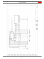
3.5 Overall dimensions. . . . . . . . . . . . . . . . . . . . . . . . . . . . . . . . . . . . . . . . . . . . . . . . . . . . . . . . . . . . . . . . . . . . . . . . . . . . . . . . . . . . 7
3.6 Standard equipment . . . . . . . . . . . . . . . . . . . . . . . . . . . . . . . . . . . . . . . . . . . . . . . . . . . . . . . . . . . . . . . . . . . . . . . . . . . . . . . . . . . 7
3.7 Burner description. . . . . . . . . . . . . . . . . . . . . . . . . . . . . . . . . . . . . . . . . . . . . . . . . . . . . . . . . . . . . . . . . . . . . . . . . . . . . . . . . . . . . 8
3.8 Firing rates . . . . . . . . . . . . . . . . . . . . . . . . . . . . . . . . . . . . . . . . . . . . . . . . . . . . . . . . . . . . . . . . . . . . . . . . . . . . . . . . . . . . . . . . . . 9
3.8.1 Minimum furnace dimensions. . . . . . . . . . . . . . . . . . . . . . . . . . . . . . . . . . . . . . . . . . . . . . . . . . . . . . . . . . . . . . . . . . . . . . . . . . . . 9
3.9 Procedure to refer burner operating condition in high altitude plants . . . . . . . . . . . . . . . . . . . . . . . . . . . . . . . . . . . . . . . . . . . . . 10
4 Installation. . . . . . . . . . . . . . . . . . . . . . . . . . . . . . . . . . . . . . . . . . . . . . . . . . . . . . . . . . . . . . . . . . . . . . . . . . . . . . . . . . . . . . . . . 12
4.1 Boiler plate . . . . . . . . . . . . . . . . . . . . . . . . . . . . . . . . . . . . . . . . . . . . . . . . . . . . . . . . . . . . . . . . . . . . . . . . . . . . . . . . . . . . . . . . . 12
4.2 Blast tube length. . . . . . . . . . . . . . . . . . . . . . . . . . . . . . . . . . . . . . . . . . . . . . . . . . . . . . . . . . . . . . . . . . . . . . . . . . . . . . . . . . . . . 12
4.3 Securing the burner to the boiler . . . . . . . . . . . . . . . . . . . . . . . . . . . . . . . . . . . . . . . . . . . . . . . . . . . . . . . . . . . . . . . . . . . . . . . . 12
4.4 Combustion head calibration . . . . . . . . . . . . . . . . . . . . . . . . . . . . . . . . . . . . . . . . . . . . . . . . . . . . . . . . . . . . . . . . . . . . . . . . . . . 12
4.5 Nozzle selection . . . . . . . . . . . . . . . . . . . . . . . . . . . . . . . . . . . . . . . . . . . . . . . . . . . . . . . . . . . . . . . . . . . . . . . . . . . . . . . . . . . . . 13
4.6 Nozzle assembly. . . . . . . . . . . . . . . . . . . . . . . . . . . . . . . . . . . . . . . . . . . . . . . . . . . . . . . . . . . . . . . . . . . . . . . . . . . . . . . . . . . . . 13
4.7 Adjustments before first firing (light-oil operation). . . . . . . . . . . . . . . . . . . . . . . . . . . . . . . . . . . . . . . . . . . . . . . . . . . . . . . . . . . . 14
4.8 Oil hydraulic system layout. . . . . . . . . . . . . . . . . . . . . . . . . . . . . . . . . . . . . . . . . . . . . . . . . . . . . . . . . . . . . . . . . . . . . . . . . . . . . 15
4.8.1 Oil pressure switch . . . . . . . . . . . . . . . . . . . . . . . . . . . . . . . . . . . . . . . . . . . . . . . . . . . . . . . . . . . . . . . . . . . . . . . . . . . . . . . . . . . 15
4.9 Hydraulic connections. . . . . . . . . . . . . . . . . . . . . . . . . . . . . . . . . . . . . . . . . . . . . . . . . . . . . . . . . . . . . . . . . . . . . . . . . . . . . . . . . 15
4.9.1 SUNTEC AJ4 CC pump . . . . . . . . . . . . . . . . . . . . . . . . . . . . . . . . . . . . . . . . . . . . . . . . . . . . . . . . . . . . . . . . . . . . . . . . . . . . . . . 16
4.9.2 Priming pump . . . . . . . . . . . . . . . . . . . . . . . . . . . . . . . . . . . . . . . . . . . . . . . . . . . . . . . . . . . . . . . . . . . . . . . . . . . . . . . . . . . . . . . 16
4.10 Fuel supply . . . . . . . . . . . . . . . . . . . . . . . . . . . . . . . . . . . . . . . . . . . . . . . . . . . . . . . . . . . . . . . . . . . . . . . . . . . . . . . . . . . . . . . . . 16
4.11 Gas line. . . . . . . . . . . . . . . . . . . . . . . . . . . . . . . . . . . . . . . . . . . . . . . . . . . . . . . . . . . . . . . . . . . . . . . . . . . . . . . . . . . . . . . . . . . . 17
4.12 Gas train. . . . . . . . . . . . . . . . . . . . . . . . . . . . . . . . . . . . . . . . . . . . . . . . . . . . . . . . . . . . . . . . . . . . . . . . . . . . . . . . . . . . . . . . . . . 17
4.13 Gas pressure . . . . . . . . . . . . . . . . . . . . . . . . . . . . . . . . . . . . . . . . . . . . . . . . . . . . . . . . . . . . . . . . . . . . . . . . . . . . . . . . . . . . . . . 18
4.14 Adjustments before first firing . . . . . . . . . . . . . . . . . . . . . . . . . . . . . . . . . . . . . . . . . . . . . . . . . . . . . . . . . . . . . . . . . . . . . . . . . . . 19
4.15 Servomotor. . . . . . . . . . . . . . . . . . . . . . . . . . . . . . . . . . . . . . . . . . . . . . . . . . . . . . . . . . . . . . . . . . . . . . . . . . . . . . . . . . . . . . . . . 20
4.16 Cams and trim potentiometers functions . . . . . . . . . . . . . . . . . . . . . . . . . . . . . . . . . . . . . . . . . . . . . . . . . . . . . . . . . . . . . . . . . . 21
4.17 Burner starting . . . . . . . . . . . . . . . . . . . . . . . . . . . . . . . . . . . . . . . . . . . . . . . . . . . . . . . . . . . . . . . . . . . . . . . . . . . . . . . . . . . . . . 21
4.17.1 Fuel oil adjustment . . . . . . . . . . . . . . . . . . . . . . . . . . . . . . . . . . . . . . . . . . . . . . . . . . . . . . . . . . . . . . . . . . . . . . . . . . . . . . . . . . . 21
4.17.2 Gas adjustment. . . . . . . . . . . . . . . . . . . . . . . . . . . . . . . . . . . . . . . . . . . . . . . . . . . . . . . . . . . . . . . . . . . . . . . . . . . . . . . . . . . . . . 21
4.17.3 Maximum output. . . . . . . . . . . . . . . . . . . . . . . . . . . . . . . . . . . . . . . . . . . . . . . . . . . . . . . . . . . . . . . . . . . . . . . . . . . . . . . . . . . . . 22
4.17.4 Minimum output . . . . . . . . . . . . . . . . . . . . . . . . . . . . . . . . . . . . . . . . . . . . . . . . . . . . . . . . . . . . . . . . . . . . . . . . . . . . . . . . . . . . . 22
4.17.5 Intermediate outputs. . . . . . . . . . . . . . . . . . . . . . . . . . . . . . . . . . . . . . . . . . . . . . . . . . . . . . . . . . . . . . . . . . . . . . . . . . . . . . . . . . 22
4.17.6 Gas combustion checks . . . . . . . . . . . . . . . . . . . . . . . . . . . . . . . . . . . . . . . . . . . . . . . . . . . . . . . . . . . . . . . . . . . . . . . . . . . . . . . 22
4.18 Air pressure switch . . . . . . . . . . . . . . . . . . . . . . . . . . . . . . . . . . . . . . . . . . . . . . . . . . . . . . . . . . . . . . . . . . . . . . . . . . . . . . . . . . . 23

6046 2
Contents
4.19 High gas pressure switch . . . . . . . . . . . . . . . . . . . . . . . . . . . . . . . . . . . . . . . . . . . . . . . . . . . . . . . . . . . . . . . . . . . . . . . . . . . . . . 23
4.20 Low gas pressure switch . . . . . . . . . . . . . . . . . . . . . . . . . . . . . . . . . . . . . . . . . . . . . . . . . . . . . . . . . . . . . . . . . . . . . . . . . . . . . . 23
5 Maintenance . . . . . . . . . . . . . . . . . . . . . . . . . . . . . . . . . . . . . . . . . . . . . . . . . . . . . . . . . . . . . . . . . . . . . . . . . . . . . . . . . . . . . . . 24
5.1 Opening the burner. . . . . . . . . . . . . . . . . . . . . . . . . . . . . . . . . . . . . . . . . . . . . . . . . . . . . . . . . . . . . . . . . . . . . . . . . . . . . . . . . . . 25
5.1.1 To open the burner. . . . . . . . . . . . . . . . . . . . . . . . . . . . . . . . . . . . . . . . . . . . . . . . . . . . . . . . . . . . . . . . . . . . . . . . . . . . . . . . . . . 25
5.1.2 To close the burner. . . . . . . . . . . . . . . . . . . . . . . . . . . . . . . . . . . . . . . . . . . . . . . . . . . . . . . . . . . . . . . . . . . . . . . . . . . . . . . . . . . 25
6 Electrical system . . . . . . . . . . . . . . . . . . . . . . . . . . . . . . . . . . . . . . . . . . . . . . . . . . . . . . . . . . . . . . . . . . . . . . . . . . . . . . . . . . . 26
6.1 Electrical wiring. . . . . . . . . . . . . . . . . . . . . . . . . . . . . . . . . . . . . . . . . . . . . . . . . . . . . . . . . . . . . . . . . . . . . . . . . . . . . . . . . . . . . . 26
6.2 Flame signal measurement . . . . . . . . . . . . . . . . . . . . . . . . . . . . . . . . . . . . . . . . . . . . . . . . . . . . . . . . . . . . . . . . . . . . . . . . . . . . 26
6.3 Operation layout. . . . . . . . . . . . . . . . . . . . . . . . . . . . . . . . . . . . . . . . . . . . . . . . . . . . . . . . . . . . . . . . . . . . . . . . . . . . . . . . . . . . . 27
6.3.1 Firing failure . . . . . . . . . . . . . . . . . . . . . . . . . . . . . . . . . . . . . . . . . . . . . . . . . . . . . . . . . . . . . . . . . . . . . . . . . . . . . . . . . . . . . . . . 27
6.3.2 Burner flame goes out during operation. . . . . . . . . . . . . . . . . . . . . . . . . . . . . . . . . . . . . . . . . . . . . . . . . . . . . . . . . . . . . . . . . . . 27
7 Faults - Possible causes - Solutions . . . . . . . . . . . . . . . . . . . . . . . . . . . . . . . . . . . . . . . . . . . . . . . . . . . . . . . . . . . . . . . . . . . 33
8 Spare parts . . . . . . . . . . . . . . . . . . . . . . . . . . . . . . . . . . . . . . . . . . . . . . . . . . . . . . . . . . . . . . . . . . . . . . . . . . . . . . . . . . . . . . . . 35
8.1 Exploded spare parts list . . . . . . . . . . . . . . . . . . . . . . . . . . . . . . . . . . . . . . . . . . . . . . . . . . . . . . . . . . . . . . . . . . . . . . . . . . . . . . 35
8.2 Spare parts list . . . . . . . . . . . . . . . . . . . . . . . . . . . . . . . . . . . . . . . . . . . . . . . . . . . . . . . . . . . . . . . . . . . . . . . . . . . . . . . . . . . . . . 36

Information and general instructions
3 6046
1.1 Information about the instruction manual
1.1.1 Introduction
The instruction manual supplied with the burner:
is an integral and essential part of the product and must not be
separated from it; it must therefore be kept carefully for any
necessary consultation and must accompany the burner even
if it is transferred to another owner or user, or to another sys-
tem. If the manual is lost or damaged, another copy must be
requested from the Technical Assistance Service of the area;
is designed for use by qualified personnel;
offers important indications and instructions relating to the
installation safety, start-up, use and maintenance of the
burner.
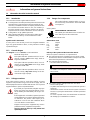
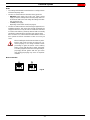
Symbols used in the manual
In some parts of the manual you will see triangular DANGER
signs. Pay great attention to these, as they indicate a situation
of potential danger.
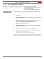
1.1.2 General dangers
The dangers can be of 3 levels, as indicated below.
1.1.3 Safety precautions
Good safety practices must be used when working on burner
equipment. The potential energy in the electrical supply, fuel and
related equipment must be handled with extreme care to prevent
equipment failures, injuries and potential death.
1.1.4 Danger: live components
Other symbols
This symbol indicates a list.
Abbreviations used
Ch. Chapter
Fig. Figure
Pag. Page
Sec. Section
Tab. Table
Delivery of the system and the instruction manual
When the system is delivered, it is important that:
The instruction manual is supplied to the user by the system
manufacturer, with the recommendation to keep it in the room
where the heat generator is to be installed.
The instruction manual shows:
– the serial number of the burner;
– the address and telephone number of the nearest Assis-
tance Centre;
The system supplier carefully informs the user about:
– the use of the system,
– any further tests that may be necessary before the system is
started up,
– maintenance and the need to have the system checked at
least once a year by the manufacturer or another specialised
technician.
To ensure a periodic check, the manufacturer recommends
the drawing up of a Maintenance Contract.
1 Information and general instructions
DANGER
Maximum danger level!
This symbol indicates operations which, if not car-
ried out correctly, cause serious injury, death or
long-term health risks.
WARNING
This symbol indicates operations which, if not car-
ried out correctly, may cause serious injury, death
or long-term health risks.
CAUTION
This symbol indicates operations which, if not car-
ried out correctly, may cause damage to the ma-
chine and/or injury to people.
WARNING
If you smell gas, open window, extinguish any open
flames, stay away from electrical switches, evacu-
ate the building and immediately call the gas com-
pany.
If this equipment is not installed, operated, operated
and maintained in accordance with the manufactur-
ers intructions, this product could expose you to
substances in fuel or from fuel combustion which
can cause death or serious illness.
Improper servicing of this equipment may create a
potential hazard to equipment and operators.
Servicing must be done by a fully trained and
qualified personnel.
DANGER
This symbol indicates operations which, if not car-
ried out correctly, lead to electric shocks with lethal
consequences.
ENVIRONMENTAL PROTECTION
This symbol gives indications for the use of the ma-
chine with respect for the environment.
............................................................................................
...........................................................................................
...........................................................................................
...........................................................................................

6046 4
Information and general instructions
1.2 Guarantee and responsibility
The manufacturer guarantees its new products from the installa-
tion date, in accordance with the regulations in force and/or the
sales contract. At the moment of the first start-up, check that the
burner is integral and complete.
In particular, the rights to the guarantee and the responsibility
will no longer be valid, in the event of damage to things or injury
to people, if such damage/injury was due to any of the following
causes:
incorrect installation, start-up, use and maintenance of the
burner;
improper, incorrect or unreasonable use of the burner;
intervention of unqualified personnel;
carrying out of non authorised modifications on the equipment;
use of the burner with safety devices that are faulty, incorrectly
applied and/or not working;
installation of untested supplementary components on the
burner;
powering of the burner with unsuitable fuels;
faults in the fuel power supply system;
use of the burner even following an error and/or an irregularity;
repairs and/or overhauls incorrectly carried out;
modification of the combustion chamber with inserts that pre-
vent the regular development of the flame, as structurally
established;
insufficient and inappropriate surveillance and care of those
burner components most subject to wear and tear;
use of non-original components, including spare parts, kits,
accessories and optionals;
force majeure.
the manufacturer furthermore declines any and every re-
sponsibility for the failure to observe the contents of this
manual.
1.2.1 Owner’s responsibility
Please pay attention to the Safety Warnings contained within
this instruction manual. Keep this manual for your records and
provide it to your quali fi ed service agency for use in profession-
ally setting up and maintaining your burner.
Your burner will provide years of ef fi cient operation if it is pro-
fessionally installed and maintained by a qualifi ed service tech-
nician. If at any time the burner does not appear to be operating
properly, immediately contact your qualifi ed service agency for
consultation.
We recommend annual inspection/service of your gas heating
system by a qualifi ed service agency.
Failure to follow these instructions, misuse, or incorrect adjust-
ment of the burner could lead to equipment malfunction and re-
sult in asphyxiation, explosion or fire.
WARNING
Failure to observe the information given in this man-
ual, operating negligence, incorrect installation and
the carrying out of non authorised modifications will
result in the annulment by the manufacturer of the
guarantee that it supplies with the burner.
WARNING
If you smell gas:
Do not touch any electrical items.
Open all windows.
Close all gas supply valves.
Contact your local gas authority immediately.
• Do not store flammable or hazardous materials
in the vicinity of fuel burning appliances.
• Improper installation, adjustment, alteration,
service or maintenance can cause property
damage, personal injury or death.
• Refer to this manual for instructional or addition-
al information.
• Consult a certified installer, service representa-
tive or the gas supplier for further assistance.
• Burner shall be installed in accordance with
manufacturers requirements as outlined in this
manual, local codes and authorities having ju-
risdiction.

Safety and prevention
5 6046
2.1 Introduction
The burners have been designed and built in compliance with
current regulations and directives, applying the known technical
rules of safety and envisaging all the potential danger situations.
It is necessary, however, to bear in mind that the imprudent and
clumsy use of the equipment may lead to situations of death risk
for the user or third parties, as well as the damaging of the burn-
er or other items. Inattention, thoughtlessness and excessive
confidence often cause accidents; the same applies to tiredness
and sleepiness.
It is a good idea to remember the following:
The burner must only be used as expressly described.
Any other use should be considered improper and therefore
dangerous.
In particular:
it can be applied to boilers operating with water, steam,
diathermic oil, and to other users expressly named by the
manufacturer;
the type and pressure of the fuel, the voltage and frequency of
the electrical power supply, the minimum and maximum deliv-
eries for which the burner has been regulated, the pressurisa-
tion of the combustion chamber, the dimensions of the
combustion chamber and the room temperature must all be
within the values indicated in the instruction manual.
Modification of the burner to alter its performance and destina-
tions is not allowed.
The burner must be used in exemplary technical safety condi-
tions. Any disturbances that could compromise safety must be
quickly eliminated.
Opening or tampering with the burner components is not
allowed, apart from the parts requiring maintenance.
Only those parts envisaged by the manufacturer can be
replaced.
2.2 Personnel training
The user is the person, body or company that has acquired the
machine and intends to use it for the specific purpose. He is re-
sponsible for the machine and for the training of the people
working around it.
The user:
Undertakes to entrust the machine exclusively to suitably
trained and qualified personnel.
Must take all the measures necessary to prevent unauthorised
people gaining access to the machine.
Undertakes to inform his personnel in a suitable way about the
application and observance of the safety instructions. With
that aim, he undertakes to ensure that everyone knows the
use and safety instructions for his own duties.
Must inform the manufacturer if faults or malfunctioning of the
accident prevention systems are noticed, along with any pre-
sumed danger situation.
Personnel must always use the personal protective equipment
envisaged by legislation and follow the indications given in this
manual.
Personnel must follow all the danger and caution indications
shown on the machine.
Personnel must not carry out, on their own initiative, opera-
tions or interventions that are not within their province.
Personnel are obliged to inform their superiors of every prob-
lem or dangerous situation that may arise.
The assembly of parts of other makes, or any modifications,
can alter the characteristics of the machine and hence com-
promise operating safety. The manufacturer therefore
declines any and all responsibility for any damage that may
be caused by the use of non-original parts.
2 Safety and prevention

6046 6
Technical description of the burner
3.1 Burner models designation
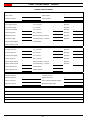
Tab. A
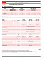
3.2 Technical data
Tab. B
(1) Reference conditions: Ambient temperature 68 °F (20°C) - Barometric pressure 394” WC - Altitude 329 ft.
(2) Pressure at test point 7) (Fig. 3, page 8) with zero pressure in the combustion chamber and maximum burner output.
(3) Sound pressure measured in manufacturer’s combustion laboratory, with burner operating on test boiler and at maximum rated output.
(4) Equivalent Btu values based on 1 USGPH = 140,000 Btu/hr.
3 Technical description of the burner
Model Code Voltage Flame safeguard
RLS 70 C9534000 (3485070)
C9534001 (3485075) 208-230/460/3/60
575/3/60 Burner mounted
Burner mounted
RLS 100 C9535000 (3485270)
C9535001 (3485275) 208-230/460/3/60
575/3/60 Burner mounted
Burner mounted
RLS 130 C9536000 (3485470)
C9536001 (3485475) 208-230/460/3/60
575/3/60 Burner mounted
Burner mounted
Model RLS 70 RLS 100 RLS 130
Output (1)
Delivery (1)
High MBtu/hr (4) 1750 - 3094 2646 - 4396 3500 - 5292
kW 513 - 907
12.5 - 22.1 775 - 1288
18.9 - 31.4 1026 - 1551
25 - 37.8
GPH
Low MBtu/hr (4) 854 1330 1750
kW 250
6.1 390
9.5 513
12.5
GPH
Fuel #2 Fuel oil
Natural gas / Propane gas
Gas pressure at maximum delivery (2)
Gas: Natural gas “ WC 2.44 3.94 4.29
Operation Low-high light oil
Low-high-low / modulating gas
Nozzles number 2
Standard applications Boilers: water, steam, thermal oil
Ambient temperature °F 32 - 104 (0 - 40 °C)
Combustion air temperature °F max 140 (60 °C)
Main power supply (+/- 10%) V/Ph/Hz 208 - 230 / 460 / 575 /3/60
Electric motors rpm 3400
Fan motor V
W - HP
A
208 - 230 / 460 / 575
1100 - 1.5
4.8 - 2.8 - 2.0
208 - 230 / 460 / 575
1800 - 2.5
6.7 - 3.9 - 2.8
208 - 230 / 460 / 575
2200 - 3
8.8 - 5.1 - 3.7
Pump motor V
W - HP
A
208 - 230 / 460 / 575
550 - 0.75
2.6 - 1.5 - 1.1
Ignition transformer Oil V1 - V2
I1 - I2 120 V - 2 x 5 kV
3.7 A - 35 mA
Gas V1 - V2
I1 - I2 120 V - 1 x 7 kV
1.6 A - 23 mA
Pumpdelivery (at 174 PSI)
pressure range
fuel temperature
GPH
PSI
° F max
54
145 - 290
140 (60 °C)
Electrical power consumption W max 2200 3000 3400
Electrical protection NEMA 1
Noise levels (3) dBA 74 77.5 80

Technical description of the burner
7 6046
3.3 Accessories (optional)
• Kit for lengthening the combustion head •Kit for LPG operation - Code 3010305: The kit allows the RLS
70-100-130 burners to operate on LPG.
•Gas train according to UL Standards: see page 17.
NOTE:
The installer is responsible for the supply and installation of
any required safety device(s) not indicated in this manual.
3.4 Packaging - weight - Approximate measurements
• The burners are skid mounted. Outer dimensions of packaging
are indicated in (Tab. C).
• The weight of the burner complete with packaging is indicated
in (Tab. C).
Tab. C
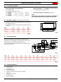
3.5 Overall dimensions
The maximum dimensions of the burners are given in (Fig. 2).
Inspection of the combustion head requires the burner to be
opened and the rear part withdrawn on the slide bars.
The maximum dimension of the burner when open, without casing,
is give in measurement I.
Tab. D
3.6 Standard equipment
1 - Gas train flange
1 - Flange gasket
4 - Flange fixing screws
1 - Burner head gasket
4 - Screws to secure the burner flange to the boiler:
1/2 W x 13/8”
1 - Adaptor G 1/8“ / 1/8“ NPT
2 - Flexible hoses
1 - Instruction booklet
L = Standard length
L1 = Length obtainable with the kit
Code 3010267 L = 9 27/32” L1 = 15 5/32” • RLS 70
Code 3010268 L = 9 27/32” L1 = 15 5/32” • RLS 100
Code 3010269 L = 9 27/32” L1 = 15 5/32” • RLS 130
inch A B C lbs
RLS 70 46 27/32“ 29 1/8“ 27 1/4“ 159
RLS 100 46 27/32“ 29 1/8“ 27 1/4“ 165
RLS 130 46 27/32“ 29 1/8“ 27 1/4“ 170
Fig. 1
D36
Fig. 2
D2300
RLS A B C D E F G H I L M N O
70 27 1/2“ 11 3/8“ 16 1/8“ 21 27/32“ 33 3/32“ 9 27/32“ 7 1/16“ 16 15/16“ 45 23/32“ 8 7/16“ 5 9/32” 8 23/32“ 2“
100 28 7/8“ 12 25/32“ 16 1/8“ 21 27/32“ 33 3/32“ 9 27/32“ 7 1/16“ 16 15/16“ 45 23/32“ 8 7/16“ 5 9/32” 8 23/32“ 2“
130 28 7/8“ 12 25/32“ 16 1/8“ 21 27/32“ 33 3/32“ 9 27/32“ 7 7/16“ 16 15/16“ 45 23/32“ 8 7/16“ 5 9/32” 8 23/32“ 2“

6046 8
Technical description of the burner
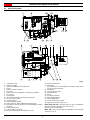
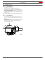
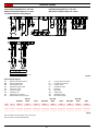
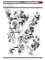
3.7 Burner description
1 Combustion head
2 Ignition electrodes
3 Screw for combustion head adjustment
4 Sleeve
5 Relay for oil / gas selection
6Fan motor
7 Motors contactors and thermal cut-out with reset button
8 UV scanner
9 Terminal strip
10 Knockouts for electrical connections by installer
11 Oil / gas selector switch
12 Flame safeguard
13 Flame inspection window
14 Low air pressure switch (differential operating type)
15 Slide bars for opening the burner and inspecting the combus-
tion head
16 Safety solenoid valve
17 Low and high fire oil valves
18 Gas pressure test point and head fixing screw
19 Air pressure test point
20 Servomotor
When the burner is not operating the air damper is fully closed
in order to reduce heat loss.
21 Pump motor
22 Low oil pressure switch
23 Pilot attachment
24 Pump
25 Gas input connection
26 Boiler mounting flange
27 Flame stability disk
28 Screw securing fan to sleeve
Two types of burner failure may occur:
Flame relay lock-out: if the flame relay 12) (Fig. 3) pushbutton
lights up, it indicates that the burner is in lock-out.
To reset, press the pushbutton.
Motor trip: release by pressing the pushbutton on the thermal
overload 7) (Fig. 3).
Fig. 3
D2299

Technical description of the burner
9 6046
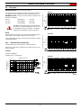
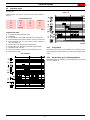
3.8 Firing rates
MAXIMUM OUTPUT must be selected in area A.
In order to increase to area B (RLS 130) it is necessary to perform
the calibration of the combustion head as explained on page 12.
MINIMUM OUTPUT must not be lower than the minimum limit
shown in the diagram:
NOTE:
The firing rates areas given in (Fig. 5) have been reduced by 10%
with respect to the maximum range that can be reached.
Consult Procedure on page 10 to refer burner operating condition
in high altitude plants.
3.8.1 Minimum furnace dimensions
The firing rates were set in relation to certified test boilers.
Figure (Fig. 4) indicates the diameter and length of the test com-
bustion chamber.
Example
Output 2579 MBtu/hr:
diameter 24 inch - length 6.6 ft.
RLS 70 = 854 MBtu/hr = 6.1 GPH
RLS 100 = 1330 MBtu/hr = 9.5 GPH
RLS 130 = 1750 MBtu/hr = 12.5 GPH
WARNING
The FIRING RATE area values have been obtained
considering an ambient temperature of 68 °F, and
an atmospheric pressure of 394” WC and with the
combustion head adjusted as shown on page 14.
Fig. 4
D2919 Diameter (inches)
Length (ft)
Furnace dimensions
Fig. 5
RLS 70
RLS 100
RLS 130
Combustion chamber pressure
“WC
Combustion chamber pressure
“WC
Combustion chamber pressure
“WC
AB
A
A

6046 10
Technical description of the burner
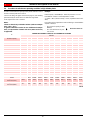
3.9 Procedure to refer burner operating condition in high altitude plants
Find the corrected burner capacity for the plant’s altitude in chart 1
and the corrected pressure in chart 2.
Check in the firing rate graph of the burner page 9, if the working
point defined by the values above is within the range limits.
If not, higher burner size is needed.
NOTE:
Charts are based only on altitude variation (reference temper-
ature = 68°F , 20°C)
To get the combined correction in case of different air temper-
ature, a compensation of 1000 ft each 20°F (305 m each 11°C)
is applicable.
Example
Rated capacity = 3000 MBtu/hr - Rated air pressure = 1.5”w.c.
Real altitude = 5000 ft - Real temperature = 108°F
= 108°F - 68°F (reference temp.) = 40°F (equivalent 2000 ft vari-
ation)
Proceeding as descripted above and considering a “virtual altitude”
of (5000 + 2000) ft:
Tab. E
– the corrected capacity is 3847
MBtu/hr;
– the corrected burner air pres-
sure is 1.92.
Burner RLS 100 is OK
1CORRECTED BURNER CAPACITY ACCORDING TO ALTITUDE
Altitude
Rated Capacity m. a.s.l. 0100 305 610 915 1220 1525 1830 2135 2440
ft a.s.l 0328 1000 2000 3000 4000 5000 6000 7000 8000
500 494 500 512 530 551 571 593 616 641 669
1000 987 1000 1023 1061 1101 1142 1186 1232 1282 1337
1500 1481 1500 1535 1591 1652 1713 1778 1848 1924 2006
2000 1974 2000 2046 2121 2202 2284 2371 2464 2565 2675
2500 2468 2500 2558 2652 2753 2855 2964 3079 3206 3343
3000 2962 3000 3069 3182 3303 3425 3557 3695 3847 4012
3500 3455 3500 3581 3712 3854 3996 4149 4311 4488 4680
4000 3949 4000 4092 4243 4404 4567 4742 4927 5130 5349
4500 4442 4500 4604 4773 4955 5138 5335 5543 5771 6018
5000 4936 5000 5116 5303 5505 5709 5928 6159 6412 6686
5500 5429 5500 5627 5834 6056 6280 6520 6775 7053 7355
6000 5923 6000 6139 6364 6606 6851 7113 7391 7694 8024
6500 6417 6500 6650 6894 7157 7422 7706 8006 8335 8692
7000 6910 7000 7162 7425 7708 7993 8299 8622 8977 9361
7500 7404 7500 7673 7955 8258 8564 8892 9238 9618 10029
8000 7897 8000 8185 8485 8809 9135 9484 9854 10259 10698
8500 8391 8500 8697 9016 9359 9705 10077 10470 10900 11367
9000 8885 9000 9208 9546 9910 10276 10670 11086 11541 12035
9500 9378 9500 9720 10076 10460 10847 11263 11702 12183 12704
10000 9872 10000 10231 10607 11011 11418 11855 12318 12824 13373
Average barometric
Pressure (20°C) mbar 1013 1000 977,4 942,8 908,2 875,8 843,5 811,85 779,8 747,8
Average barometric
Pressure (68°F) "w.c. 399 394 385 371 358 345 332 320 307 294

Technical description of the burner
11 6046
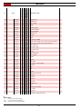
Tab. F
2CORRECTED BURNER AIR PRESSURE ACCORDING TO ALTITUDE
Altitude
Rated Pressure m. a.s.l. 0100 305 610 915 1220 1525 1830 2135 2440
ft a.s.l 0328 1000 2000 3000 4000 5000 6000 7000 8000
0,50 0,49 0,50 0,51 0,53 0,55 0,57 0,59 0,62 0,64 0,67
1,00 0,99 1,00 1,02 1,06 1,10 1,14 1,19 1,23 1,28 1,34
1,50 1,48 1,50 1,53 1,59 1,65 1,71 1,78 1,85 1,92 2,01
2,00 1,97 2,00 2,05 2,12 2,20 2,28 2,37 2,46 2,56 2,67
2,50 2,47 2,50 2,56 2,65 2,75 2,85 2,96 3,08 3,21 3,34
3,00 2,96 3,00 3,07 3,18 3,30 3,43 3,56 3,70 3,85 4,01
3,50 3,46 3,50 3,58 3,71 3,85 4,00 4,15 4,31 4,49 4,68
4,00 3,95 4,00 4,09 4,24 4,40 4,57 4,74 4,93 5,13 5,35
4,50 4,44 4,50 4,60 4,77 4,95 5,14 5,33 5,54 5,77 6,02
5,00 4,94 5,00 5,12 5,30 5,51 5,71 5,93 6,16 6,41 6,69
5,50 5,43 5,50 5,63 5,83 6,06 6,28 6,52 6,77 7,05 7,35
6,00 5,92 6,00 6,14 6,36 6,61 6,85 7,11 7,39 7,69 8,02
6,50 6,42 6,50 6,65 6,89 7,16 7,42 7,71 8,01 8,34 8,69
7,00 6,91 7,00 7,16 7,42 7,71 7,99 8,30 8,62 8,98 9,36
7,50 7,40 7,50 7,67 7,96 8,26 8,56 8,89 9,24 9,62 10,03
8,00 7,90 8,00 8,18 8,49 8,81 9,13 9,48 9,85 10,26 10,70
8,50 8,39 8,50 8,70 9,02 9,36 9,71 10,08 10,47 10,90 11,37
9,00 8,88 9,00 9,21 9,55 9,91 10,28 10,67 11,09 11,54 12,04
9,50 9,38 9,50 9,72 10,08 10,46 10,85 11,26 11,70 12,18 12,70
10,00 9,87 10,00 10,23 10,61 11,01 11,42 11,86 12,32 12,82 13,37
Average barometric
Pressure (20°C) mbar 1013 1000 977,4 942,8 908,2 875,8 843,5 811,85 779,8 747,8
Average barometric
Pressure (68°F) "w.c. 399 394 385 371 358 345 332 320 307 294

6046 12
Installation
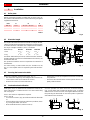
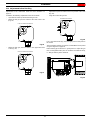
4.1 Boiler plate
Drill the combustion chamber mounting plate as shown in (Fig. 6).
The position of the threaded holes can be marked using the gasket
supplied with the burner.
Tab. G
4.2 Blast tube length
The length of the blast tube must be selected according to the indi-
cations provided by the manufacturer of the boiler, it must be great-
er than the thickness of the boiler door complete with its insulation.
The range of lengths available, L (inch), is as follows:
For boilers with front flue passes 13) or flame inversion chambers,
insulation material 11) must be inserted between the refractory 12)
and the blast tube 10).
This protective insulation must not compromise the extraction of
the blast tube.
For boilers having a water-cooled front, the insulation 11)-12)
(Fig. 7) is not required unless it is required by the boiler manufac-
turer.
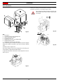
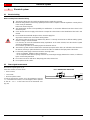
4.3 Securing the burner to the boiler
Detach the combustion head from the burner, (Fig. 7):
– Disconnect the oil pipes by unscrewing the two connectors 6)
– Loosen the 4 screws 3) and remove the cover 1)
– Remove the screws 2) from the slide bars 5)
– Remove the 2 screws 4) and pull the burner back on slide bars
5) by about 4”.
– Disconnect the electrode wires and then pull the burner com-
pletely off the slide bars.
4.4 Combustion head calibration
At this point check, on model RLS 130, whether the maximum de-
livery of the burner is contained in area A or in area B of the firing
rate. See page 9.
If it is in area A then no adjustment is required.
If it is in area B:
– Unscrew the screws 1) (Fig. 8) and disassemble the blast tube
2).
– Move the fixing of the rod 3) from position A to position B, there-
by causing the shutter 4) to retract.
– Now refit the blast tube 2) and the screws 1).
Once this operation has been carried out, secure the flange 9)
(Fig. 7) to the boiler plate, inserting the gasket 7) (Fig. 7) supplied
with the burner. Use the 4 screws, also supplied with the unit, after
first protecting the thread with an anti-seize product. Tighten the
seal between burner and boiler.
4Installation
inch A B C
RLS 70 7 9/32“10 27/32“ - 12 25/32“1/2 W
RLS 100 7 21/32“10 27/32“ - 12 25/32“1/2 W
RLS 130 7 21/32“10 27/32“ - 12 25/32“1/2 W
Fig. 6
D455
Blast tube 10): RLS 70 RLS 100 RLS 130
• short 9 27/32“9
27/32“9
27/32“
• long 1 55/32“1
55/32“1
55/32“
Fig. 7
D2302
Fig. 8
D1192

Installation
13 6046
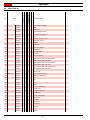
4.5 Nozzle selection
Both nozzles must be chosen from among those listed in (Tab. H).
The first nozzle determines the delivery of the burner in low fire.
The second nozzle combines together with the 1st nozzle to deter-
mine the total firing rate at high fire.
The total firing rates of low and high fire must be contained within
the value range indicated on page 6.
Use nozzles with a 60° spray angle at the recommended pressure
of 174 PSI.
The two nozzles have equal deliveries rates.
Tab. H
4.6 Nozzle assembly
Remove screw 1) (Fig. 9) and extract the nozzle assembly 2). In-
stall both nozzles 1) (Fig. 10), after having removed the plastic
plugs 2) (Fig. 10), fitting the wrench through the central hole in the
flame stability disk or loosen screws 1) (Fig. 11), remove disk 2)
(Fig. 11) and replace the nozzles using the wrench 3) (Fig. 11).
Do not use any sealing products such as gaskets, sealing com-
pound, or tape. Be careful to avoid damaging the nozzle sealing
seat. The nozzles must be screwed into place tightly but carefully.
The nozzle for low fire operation is the one lying beneath the firing
electrodes (Fig. 12).
Make sure that the electrodes are positioned as shown in (Fig. 12).
Electrode position (for oil operation)
Nozzle
size GPH MBtu/hr
174 PSI
145 PSI 174 PSI 203 PSI
5.00
5.50
6.00
6.50
7.00
7.50
8.00
8.30
8.50
9.00
9.50
10.0
10.5
11.0
12.0
12.3
13.0
13.8
14.0
15.0
15.3
16.0
17.0
6.15
6.76
7.4
8.01
8.61
9.22
9.86
10.21
10.47
11.08
11.69
12.3
12.94
13.54
14.76
15.15
16.01
17.0
17.23
18.48
18.83
19.69
20.94
6.79
7.46
8.17
8.84
9.51
10.18
10.86
11.27
11.56
12.23
12.90
13.58
14.28
14.95
16.3
16.71
17.64
18.73
19.02
20.37
20.78
21.74
23.09
7.4
8.13
8.87
9.61
10.34
11.08
11.82
12.26
12.55
13.29
14.03
14.76
15.49
16.23
17.71
18.16
19.18
20.27
20.65
22.16
22.57
23.63
25.1
951
1044
1144
1238
1331
1425
1520
1578
1618
1712
1806
1901
1999
2093
2282
2339
2470
2622
2663
2852
2909
3044
3514
Fig. 9
D1122
Fig. 10
D1146
Fig. 11
D1147
Fig. 12
D2539

6046 14
Installation
Refit the burner to the slide bars 3) (Fig. 13) at approximately 4”
from the sleeve 4) - burner positioned as shown in (Fig. 7, page 12)
- insert the ignition electrode cables and then slide the burner up to
the sleeve so that it is positioned as shown in (Fig. 13).
Refit screws 2) (Fig. 13) on slide bars 3).
Secure the burner to the sleeve by tightening screws 1).
Connect the oil pipes again by screwing on the two connectors 6)
(Fig. 7, page 12).
4.7 Adjustments before first firing (light-oil operation)
• Combustion head setting
The setting of the combustion head depends exclusively on the
maximum delivery of the burner.
Turn screw 5) (Fig. 14) until the notch shown in diagram (Fig. 15)
is level with the front surface of flange 6) (Fig. 14).
Example: Burner RLS 100
maximum burner delivery = 23.1 GPH.
If diagram (Fig. 15) is consulted it is clear that for this delivery, the
combustion head must be adjusted using notch 3, as shown in
(Fig. 14).
NOTE:
In case of high altitude installation site, head setting must re-
fer to the “corrected capacity” according procedure descript-
ed at page 10.
• Pump adjustment
No settings are required for the pump, which is set to 174 PSI by
the manufacturer. This pressure must be checked and adjusted (if
required) after the burner has been ignited.
The only operation required in this phase is the application of a
pressure gauge on the appropriate pump attachment.
• Air damper adjustment
The first time the burner is fired leave the factory setting unchanged
for both low and high fire operation.
• Ignition pilot adjustment
Place the pilot and electrode as shown in (Fig. 16).
The pilot works correctly at pressures ranging from 6 - 12” WC.
WARNING
When fitting the burner on the two slide bars, it is
advisable to gently draw out the high tension cables
until they are slightly stretched.
Fig. 13
D2305
Fig. 14
D1149
Fig. 15
N° Notches
Maximum fuel oil delivery USGPH
D2304
WARNING
To set the pilot without main burner operation, pro-
ceed as follows:
– Move the jumper from terminals "30-V11" to
terminals "30-VP", as given in (Fig. 17), this
way the main valve will not be energized.
– With the burner in the manual position, hold the
air damper in the minimum position and make
the setting.
– When the setting is correct, replace the jumper
on “30-V11”.
Fig. 16
Ignition pilot
Electrode
D2591
1/32”
Fig. 17
MB - Burner terminal strip
D2317

Installation
15 6046
4.8 Oil hydraulic system layout
Legend (Fig. 18)
1 Pump suction
2Filter
3Pump
4 Pressure regulator
5 Return pipe
6 By-pass screw
7 Pump return
8 Safety solenoid
9 Low fire valve
10 High fire valve
11 Filter
M Pressure gauge
P low oil pressure switch
V Vacuum gauge
4.8.1 Oil pressure switch
The oil pressure switch 22) (Fig. 3, page 8) is factory set to 145 PSI
(10 bar).
If the oil pressure goes down to this value, the pressure switch
stops the burner.
4.9 Hydraulic connections
The pumps are equipped with a by-pass that separates return line
and suction line. The pumps are installed on the burner with the by-
pass closed by screw 6), see diagram Fig. 18.
It is therefore necessary to connect both hoses to the pump.
Damage to the pump seal will occur immediately if it is run
with the return line closed and the by-pass screw inserted.
Remove the plugs from the suction and return connections of the
pump.
Insert the hose connections with the supplied seals into the con-
nections and screw them down.
Take care that the hoses are not stretched or twisted during instal-
lation.
Install the hoses where they cannot be stepped on or come into
contact with hot surfaces of the boiler and where they do not ham-
per the opening of the burner.
Now connect the other end of the hoses to the suction and return
lines.
Fig. 18
D2592
Fig. 19
D2308

6046 16
Installation
4.9.1 SUNTEC AJ4 CC pump
1 Suction 1/4” NPT
2 Return 1/4” NPT
3 Pressure gauge attachment G 1/8”
4 Vacuum gauge attachment G 1/8”
5 Pressure regulator
A Min. delivery rate at 174 PSI pressure
B Delivery pressure range
C Max. suction
D Viscosity range
E Max fuel oil temperature
F Max. suction and return pressure
G Pressure calibration in the factory
H Filter mesh width
4.9.2 Priming pump
Before starting the burner, make sure that the tank return
line is not clogged.
Obstructions in the line could cause damage to the pump
seal. (The pump leaves the factory with the by-pass closed).
Also check to make sure that the valves located on the suction
line are open and that there is sufficient fuel in the tank.
For self-priming to take place, one of the screws 3) of the
pump (Fig. 20) must be loosened in order to bleed off the air
contained in the suction line.
4.10 Fuel supply
The burner is equipped with a self-priming pump which is capable
of feeding itself within the limits listed in the table at the left.
The tank higher than the burner A
The distance "P" must not exceed 33 ft in order to avoid subjecting
the pump's seal to excessive strain; the distance "V" must not ex-
ceed 13 ft in order to permit pump self-priming even when the tank
is almost completely empty.
The tank lower than the burner B
Pump suction pressures higher than 13 “Hg must not be exceeded
because at higher levels gas is released from the fuel, the pump
starts making noise and its working life-span decreases.
It is good practice to ensure that the return and suction lines enter
the burner from the same height; in this way it will be more improb-
able that the suction line fails to prime or stops priming.
Tab. I
H = Pump/Foot valve height difference
L = Piping length
Ø = Inside pipe diameter
1= Burner
2= Pump
3 = Filter
4 = Manual on/off valve
5= Suction line
6 = Foot valve
7 = Return line
AJ4 CC
A
B
C
D
E
F
G
H
GPH
PSI
“Hg
cSt
°F - °C
PSI
PSI
inch
54
145 - 290
13
2.8 - 75
140 - 60
29
174
0.006
Fig. 20
D2306
+ H
- H
ft
L ft
RLS 70 - 100 - 130
Ø inch
3/8”1/2”5/8”
+ 13
+ 10
+ 6.6
+ 3.3
+ 1.6
100
88
75
68
52
210
180
155
140
110
320
320
320
320
270
045 98 240
- 1.6
- 3.3
- 6.6
- 10
39
26
19
--
85
55
42
13
200
140
104
36
Fig. 21
6
7
53
2
1
4
- H
3 15/16
+ H V
P
5
7
A
B
6
D1178

Installation
17 6046
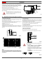
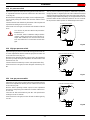
4.11 Gas line
• The main gas train must be connected to the gas attachment
1) (Fig. 22), using flange 2), gasket 3) and screws 4) supplied
with the burner.
• The main gas train can enter the burner from the right or left
side.
• Gas safety shut-off valves 5)-6) (Fig. 23) must be as close as
possible to the burner to ensure gas reaches the combustion
head within the safety time range.
• The pilot gas train must be connected to the gas attachment 5)
(Fig. 23) and can enter the burner from the right or left side.
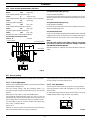
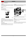
4.12 Gas train
It must be type-approved according to required Standards and is
supplied separately from the burner.
NOTE:
See the accompanying instructions for the gas train lay out.
Key to layout
1 Gas input pipe
2 Manual valve
3 Pressure regulator
4 Low gas pressure switch
5 1st safety shut off valve
6 2nd safety shut off valve
7 Standard issue burner gasket with flange
8 Gas butterfly valve
9 Burner
Fig. 22
D2310
D2311
TYPICAL UL SCHEMATIC GAS PIPING
GAS PILOT LINE
MAIN GAS LINE
Fig. 23

6046 18
Installation
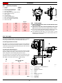
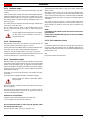
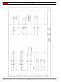
4.13 Gas pressure
The adjacent diagrams are used to calculate manifold pressure
taking into account combustion chamber pressure.
Column 1
Gas manifold pressure measured at test point 1) (Fig. 25), with:
• Combustion chamber at 0” WC
• Burner operating at maximum output
• Natural gas
Calculate the approximate high fire output of the burner as follows:
– Subtract the combustion chamber pressure from the gas pres-
sure measured at test point 1) (Fig. 25).
– Find the nearest pressure value to your result in column 1 of
the diagram for the burner in question.
– Read off the corresponding output on the left.
Example - RLS 100
A maximum output of 3616 MBtu/hr shown in diagram RLS 100
corresponds to 3.62” WC pressure, column 1, natural gas.
This value serves as a rough guide, the effective delivery must be
measured at the gas meter.
• Maximum output operation
• Natural gas
• Gas pressure at test point 1)
(Fig. 25) = 4.41” WC
• Pressure in combustion chamber = 0.79” WC
4.41 - 0.79 = 3.62” WC
D3204
p [“WC]p [“WC]p [“WC]
RLS 70
RLS 100
RLS 130
Fig. 24
D2309
1
2
Fig. 25
Page is loading ...
Page is loading ...
Page is loading ...
Page is loading ...
Page is loading ...
Page is loading ...
Page is loading ...
Page is loading ...
Page is loading ...
Page is loading ...
Page is loading ...
Page is loading ...
Page is loading ...
Page is loading ...
Page is loading ...
Page is loading ...
Page is loading ...
Page is loading ...
Page is loading ...
Page is loading ...
Page is loading ...
Page is loading ...
Page is loading ...
Page is loading ...
-
 1
1
-
 2
2
-
 3
3
-
 4
4
-
 5
5
-
 6
6
-
 7
7
-
 8
8
-
 9
9
-
 10
10
-
 11
11
-
 12
12
-
 13
13
-
 14
14
-
 15
15
-
 16
16
-
 17
17
-
 18
18
-
 19
19
-
 20
20
-
 21
21
-
 22
22
-
 23
23
-
 24
24
-
 25
25
-
 26
26
-
 27
27
-
 28
28
-
 29
29
-
 30
30
-
 31
31
-
 32
32
-
 33
33
-
 34
34
-
 35
35
-
 36
36
-
 37
37
-
 38
38
-
 39
39
-
 40
40
-
 41
41
-
 42
42
-
 43
43
-
 44
44


Riello RLS 100 Installation guide
- Category
- Fireplaces
- Type
- Installation guide
Ask a question and I''ll find the answer in the document
Finding information in a document is now easier with AI
Related papers
-
Riello RLS 28 Installation, Use And Maintenance Manual
-
Riello BG7.1D 1/230/50 Installer Manual
-
-
Riello RL28/M Installation guide
-
-
-
-
Riello RS 70/M TC FS1/FS2 3/230-400/50 230/50-60 Installer Manual
-
-
Other documents
-
Aerco MFC 8000 User manual
-
 Riello Burners RG5S 399T1 Installation, Use And Maintenance Instructions
-
 CAP GEN-2 Operating instructions
-
-
OTT Radar Level Sensor RLS Operating instructions
-
 Bentone B70-2/3 User manual
-
Viessmann VITOFLAME 100 Service Instructions Manual
-
 Bentone B70-3 Jumo User manual
-
PVI Industries Power Flame Owner's manual
-
 CleaverBrooks profire q Installation, Operation And Maintanance


