Page is loading ...

Installation, use and maintenance instructions
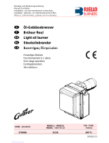
Dual Fuel Gas / Light Oil Burners
RLS 28 - 38 - 50
Low - High Operation
C6505058

2
CONTENTS
FUEL OIL / GAS
Technical data . . . . . . . . . . . . . . . . . . . . . . . . . . . . . . . . . . page 3
Burner models . . . . . . . . . . . . . . . . . . . . . . . . . . . . . . . . . . . . . . . 3
Accessories . . . . . . . . . . . . . . . . . . . . . . . . . . . . . . . . . . . . . . . . . 3
Burner description . . . . . . . . . . . . . . . . . . . . . . . . . . . . . . . . . . . . 4
Packaging - Weight. . . . . . . . . . . . . . . . . . . . . . . . . . . . . . . . . . . . 4
Max. dimensions. . . . . . . . . . . . . . . . . . . . . . . . . . . . . . . . . . . . . . 4
Standard equipment. . . . . . . . . . . . . . . . . . . . . . . . . . . . . . . . . . . 4
Firing rates . . . . . . . . . . . . . . . . . . . . . . . . . . . . . . . . . . . . . . . . . . 5
Minimum furnace dimensions. . . . . . . . . . . . . . . . . . . . . . . . . . . . 5
Installation . . . . . . . . . . . . . . . . . . . . . . . . . . . . . . . . . . . . . . . . . . 6
Boiler plate . . . . . . . . . . . . . . . . . . . . . . . . . . . . . . . . . . . . . . . . . . 6
Blast tube length . . . . . . . . . . . . . . . . . . . . . . . . . . . . . . . . . . . . . 6
Securing the burner to the boiler . . . . . . . . . . . . . . . . . . . . . . . . . 6
FUEL OIL
Choice of nozzles for 1st and 2nd stage . . . . . . . . . . . . . . . . . . . 6
Nozzle assembly . . . . . . . . . . . . . . . . . . . . . . . . . . . . . . . . . . . . . 7
Adjustments before first firing. . . . . . . . . . . . . . . . . . . . . . . . . . . . 7
FUEL OIL / GAS
Servomotor. . . . . . . . . . . . . . . . . . . . . . . . . . . . . . . . . . . . . . . . . . 8
FUEL OIL
Pump . . . . . . . . . . . . . . . . . . . . . . . . . . . . . . . . . . . . . . . . . . . . . . 8
Fuel supply. . . . . . . . . . . . . . . . . . . . . . . . . . . . . . . . . . . . . . . . . . 9
Hydraulic connections . . . . . . . . . . . . . . . . . . . . . . . . . . . . . . . . . 9
Pump priming. . . . . . . . . . . . . . . . . . . . . . . . . . . . . . . . . . . . . . . . 9
Burner calibration. . . . . . . . . . . . . . . . . . . . . . . . . . . . . . . . . . . . 10
GAS
Gas pressure . . . . . . . . . . . . . . . . . . . . . . . . . . . . . . . . . . . . . . . 11
Gas piping . . . . . . . . . . . . . . . . . . . . . . . . . . . . . . . . . . . . . . . . . 12
Adjustments before first firing. . . . . . . . . . . . . . . . . . . . . . . . . . . 13
Burner starting . . . . . . . . . . . . . . . . . . . . . . . . . . . . . . . . . . . . . . 13
Burner firing . . . . . . . . . . . . . . . . . . . . . . . . . . . . . . . . . . . . . . . . 13
Burner calibration. . . . . . . . . . . . . . . . . . . . . . . . . . . . . . . . . . . . 14
FUEL OIL / GAS
Maintenance. . . . . . . . . . . . . . . . . . . . . . . . . . . . . . . . . . . . . . . . 16
Hydraulic system layout . . . . . . . . . . . . . . . . . . . . . . . . . . . . . . . 17
ELECTRICAL
Factory wiring diagram - RLS 28-38 with burner mounted LFL . 18
Factory wiring diagram - RLS 50 with burner mounted LFL. . . . 19
Field wiring diagram - RLS 28-38-50 with burner mounted LFL 20
Factory wiring diagram - RLS 28-38-50 with remote panel . . . . 21
Appendix - Burner firing rates according to air density. . . . . . . . 22
Flame signal measurement . . . . . . . . . . . . . . . . . . . . . . . . . . . . 23
Siemens LFL control sequence of operations . . . . . . . . . . . . . . 23
Siemens LFL control troubleshooting guide . . . . . . . . . . . . . . . 24
Burner start up report. . . . . . . . . . . . . . . . . . . . . . . . . . . . . . . . . 25
WARNING
If you smell gas:
• Do not touch any electrical items.
• Open all windows.
• Close all gas supply valves.
• Contact your local gas authority immediately.
Do not store flammable or hazardous materials in the vicinity
of fuel burning appliances.
Improper installation, adjustment, alteration, service or main-
tenance can cause property damage, personal injury or
death. Refer to this manual for instructional or additional in-
formation. Consult a certified installer, service representative
or the gas supplier for further assistance.
Burner shall be installed in accordance with manufacturers
requirements as outlined in this manual, local codes and au-
thorities having juristiction.

3
TECHNICAL DATA
(1)
Reference conditions: Ambient temperature 68 °F (20°C) - Barometric pressure 394” WC - Altitude 329 ft.
(2)
Pressure at test point 7)(A)p.4 with zero pressure in the combustion chamber and maximum burner output.
(3)
Sound pressure measured in manufacturer’s combustion laboratory, with burner operating on test boiler and at maximum rated output.
(4)
Equivalent Btu values based on 1 USGPH = 140,000 Btu/hr.
Burner models designation:
Accessories
(optional):
• Kit for lengthening the combustion head
L =Standard length
L1 =Length obtainable with the kit
COD. 3010264 L = 7
1/2
” L1 = 12
27/32
” • RLS 28
COD. 3010265 L = 7
29/32
“ L1 = 13
7/32
” • RLS 38
COD. 3010266 L = 8
1/2
” L1 = 13
13/16
” • RLS 50
• Kit for LPG operation -
Code
3010304:
The kit allows the RLS 28-38-50 burners to operate on LPG
.
•
Gas train according to UL Standards:
see page 12.
MODEL RLS 28 RLS 38 RLS 50
Output
(1)
Delivery
(1)
2nd stage MBtu/hr
(4)
616 - 1232 882 - 1666 1092 - 2198
kW 181 - 361
4.4 - 8.8 258 - 488
6.3 - 11.9 320 - 644
7.8 - 15.7
GPH
min. 1st
stage MBtu/hr
(4)
378 434 546
kW 111
2.7 127
3.1 160
3.9
GPH
Fuel #2 Fuel oil
Natural gas / Propane gas
Gas pressure at maximum delivery
(2),
Gas: Natural gas ” WC 4.33 5.11 5.51
Operation low-high
Nozzles number 2
Ambient temperature °F 32 - 104 (0 - 40 °C)
Combustion air temperature °F max 140 (60 °C)
Main power supply (+/- 10%) V/Ph/Hz 120/1/60 208-230/460/575/3/60
Electric motors rpm 3400
Fan motor
Fan motor capacitor
V
W - HP
A
µF
120
370 - 0.5
5.2
45
120
370 - 0.5
5.2
45
208 - 230 / 460 / 575
550 - 0.75
3.2 - 1.6 - 1.3
n/a
Pump motor
Pump motor capacitor
V
W - HP
A
µF
120
90 - 0.12
0,8
12,5
Ignition transformer Oil V1 - V2
I1 - I2 120 V - 2 x 5 kV
3.7 A - 35 mA
Gas V1 - V2
I1 - I2 120 V - 1 x 7 kV
1.6 A - 23 mA
Pump Delivery (at 174 PSI)
Pressure range
Fuel temperature
GPH
PSI
° F max
21.5
58 - 261
140 (60 °C)
Electrical power consumption W max 760 760 910
Electrical protection NEMA 1
Noise Levels
(3)
dBA 68 70 72
Model Code Voltage Flame safeguard
RLS 28 C9531000
(3483270)
C9631000
(3483272) 120/1/60
120/1/60 Burner mounted
Remote panel
RLS 38 C9532000
(3484170)
C9632000
(3484172) 120/1/60
120/1/60 Burner mounted
Remote panel
RLS 50
C9533000
(3484670)
C9533001
(3484670)
C9633000
(3484672)
C9633001
(3484672)
208-230/460/3/60
575/3/60
208-230/460/3/60
575/3/60
Burner mounted
Burner mounted
Remote panel
Remote panel
Important:
The installer is responsible for the supply and installation of any required safety device(s) not indicated in this manual.

4
BURNER DESCRIPTION (A)
1 Combustion head
2 Ignition electrodes
3 Screw for combustion head adjustment
4 Sleeve
5 Low air pressure switch
(differential operating type)
6 Air pressure test point
7 Gas pressure test point and head fixing screw
8 Screw securing fan to sleeve
9 Slide bars for opening the burner and inspecting the
combustion head
10 Pump
11 Safety solenoid valve
12 Low and high fire oil valves
13 Servomotor
14 UV scanner
15 Plate with four hole knock-outs for flexible hoses and
electrical cable routing.
16 Air inlet to fan
17 Gas input connection
18 Boiler mounting flange
19 Flame stability disk
20 Flame inspection window
21 Oil / gas selector switch
22 Fan motor contactor and thermal overload with reset
button (RLS 50 three-phase)
23 Flame safeguard with lock-out pilot light and lock-out
reset button
24 Power switch for different operations:
automatic - manual - off
Button for:
power increase - power reduction
25 Burner terminal strip
26 Low oil pressure switch
27 Pump motor
Two types of burner failure may occur:
• Flame safeguard lock-out
:
if the flame relay 23)(A) pushbutton lights up, it indi-
cates that the burner is in lock-out.
To reset, press the pushbutton.
• Motor trip
(RLS 50 three-phase):
Release by pressing the pushbutton on the thermal
overload 22)(A).
PACKAGING - WEIGHT (B)
- Approximate measure-
ments
• The burners are shipped in cardboard boxes with the
maximum dimensions shown in table (B).
• The weight of the burner complete with packaging is
indicated in Table (B).
MAX. DIMENSIONS (C)
-
Approximate measure-
ments
The maximum dimensions of the burners are given in
(C).
Note that if you need to examine the combustion head,
the burner must be pulled backward on the slide bars and
turned upward.
The maximum dimension of the burner, without the cover,
when open is given by measurement H.
STANDARD EQUIPMENT
1 - Gas train flange
1 - Flange gasket
4 - Flange fixing screws
4 - Screws to secure the burner flange to the boiler:
3/8
W x 1”
1 - Adaptor G
1/8
“ /
1/8
“ NPT
1 - Instruction booklet
1 - Spare parts list
(A)
inch A B C lbs
RLS 28 3931/32“24
13/16“19
11/16“95
RLS 38 3931/32“24
13/16“19
11/16“99
RLS 50 3931/32“24
13/16“19
11/16“101
D88
(B)
RLS A B C D E F G H I L M
28 1823/32“18
21/32“22
13/16“7
1
/
2
“5
1
/
2
“13
27/32“6
7
/
16“31
7
/
8
“4
1
/
4
“6
5
/
8
“1
1
/
2
”
38 1823/32“18
21/32“22
13/16“7
29/32“5
31/32“13
27/32“6
7
/
16“31
7
/
8
“4
1
/
4
“6
5
/
8
“1
1
/
2
”
50 1823/32“18
21/32“22
13/16“8
1
/
2
“5
31/32“13
27/32“6
7
/
16“31
7
/
8
“4
1
/
4
“6
5
/
8
“1
1
/
2
”
(C)
D2534
D2536
D1118
D495

5
FIRING RATES (A)
The RLS 28 - 38 - 50 Model burners can work in two
ways: low and high fire.
MAXIMUM OUTPUT
must be selected in area A.
MINIMUM OUTPUT
must not be lower than the mini-
mum limit shown in the diagram:
RLS 28 = 378 MBtu/hr = 2.7 GPH
RLS 38 = 434 MBtu/hr = 3.1 GPH
RLS 50 = 546 MBtu/hr = 3.9 GPH
Important:
The firing rate area values have been obtained consider-
ing an ambient temperature of 68 °F (20°C), and an
atmospheric pressure of 394” WC and with the combus-
tion head adjusted as shown on page 7.
Note:
The FIRING RATE areas given in figure (A) have been
reduced by 10% with respect to the maximum range that
can be reached.
Consult Appendix on page 22 for operation at different
ambient temperatures and/or altitudes.
MINIMUM FURNACE DIMENSIONS (B)
The firing rates were set in relation to certified test boil-
ers.
Figure (B) indicates the diameter and length of the test
combustion chamber.
Example:
output 1388 MBtu/hr:
diameter 20 inch - length 4.9 ft.
(A)
RLS 28
RLS 38
RLS 50
Combustion chamber pressure
“WC
Combustion chamber pressure
“WC
Combustion chamber pressure
“WC
D2537
(B) D2918
Length (ft)
Furnace dimensions
Diameter (inches)

6
INSTALLATION
BOILER PLATE (A)
Drill the combustion chamber mounting plate as shown in
(A). The position of the threaded holes can be marked
using the head gasket supplied with the burner.
BLAST TUBE LENGTH (B)
The length of the blast tube must be selected according
to the indications provided by the manufacturer of the
boiler, and it must be greater than the thickness of the
boiler door complete with its insulation. The range of
lengths available, L (inch), is as follows
Blast tube 10): RLS 28 RLS 38 RLS 50
• short 7
1/2
“7
29/32
“8
1
/
2
“
• long 12
27/32
“13
7
/
32
“13
13/16
“
For boilers with front flue passes 13) or flame inversion
chambers, protective insulation 11) must be inserted be-
tween the boiler refractory 12) and the blast tube 10).
This protective insulation must not compromise the ex-
traction of the blast tube.
For boilers having a water-cooled front the insulation
11)-12)(B) is not required unless it is required by the
boiler manufacturer.
SECURING THE BURNER TO THE BOILER (B)
Detach the combustion head from the burner, fig. (B):
- disconnect the oil pipes by unscrewing the two con-
nectors 4).
- remove screw 14) and withdraw the cover 15).
- remove the screws 2) from the slide bars 3).
- remove screw 1) and pull the burner back on slide bars
3) by about 4”.
Disconnect the electrode wires and then pull the burn-
er completely off the slide bars, after removing the split
pin from the slide bar 3).
Secure the flange 9)(B) to the boiler plate, inserting the
gasket 6)(B). Use the 4 screws, also supplied with the
unit, after first protecting the thread with an anti-locking
product.
The seal between burner and boiler must be airtight.
CHOICE OF NOZZLES FOR 1ST AND 2ND STAGE
Both nozzles must be chosen from among those listed in
table (C).
The first nozzle determines the delivery of the burner at
low fire.
The second nozzle works together with the 1st nozzle to
determine the delivery of the burner at high fire.
The deliveries at low and high fire must be contained
within the value range indicated on page 3.
Use nozzles with a 60° spray angle at the recommended
pressure of 174 PSI.The two nozzles usually have equal
deliveries.
Example with the RLS 28 Model
Boiler output = 921 MBtu/hr @ efficiency 80 %
Output required by the burner =
921 / 0.8 = 1151 MBtu/hr
1151 / 2 = 576 MBtu/hr (4.0 USGPH) per nozzle
therefore, two equal, 60°, 174 PSI nozzles are
required:
1° = 4.00 GPH with 2° = 4.00 GPH,
or the following two different nozzles:
1° = 4.50 GPH with 2° = 3.50 GPH,
or:
1° = 3.50 GPH with 2° = 4.50 GPH.
(C)
inch A B C
RLS 28 69/32“8
13/16“3/8 W
RLS 38 69/32“8
13/16“3/8 W
RLS 50 69/32“8
13/16“3/8 W
D455
(A)
D2538
(B)
NOZZLE
GPH
GPH MBTU/h
145 PSI 174 PSI 203 PSI 174 PSI
RLS 28
2.00
2.25
2.50
3.00
3.50
2.47
2.75
3.07
3.68
4.32
2.72
3.04
3.39
4.07
4.74
2.95
3.33
3.68
4.42
5.16
381
426
475
570
664
RLS 38
2.50
3.00
3.50
4.00
4.50
5.00
3.07
3.68
4.32
4.93
5.54
6.15
3.39
4.07
4.74
5.44
6.12
6.79
3.68
4.42
5.16
5.89
6.63
7.36
475
570
664
762
857
951
RLS 50
3.00
3.50
4.00
4.50
5.00
5.50
6.00
3.68
4.32
4.93
5.54
6.15
6.76
7.40
4.07
4.74
5.44
6.12
6.79
7.46
8.17
4.42
5.16
5.89
6.63
7.36
8.10
8.87
570
664
762
857
951
1044
1144
60°
(D) D1122
D339

7
NOZZLE ASSEMBLY
Remove screw 1)(D)p.6 and extract the internal part
2)(D)p.6 Install two nozzles with the box wrench 1)(A),
after having removed the plastic plugs 2)(A), fitting the
wrench through the central hole in the flame stability
disk or loosen screws 1)(B), remove disk 2)(B) and
replace the nozzles using the wrench 3)(B).
Do not use any sealing products such as gaskets, seal-
ing compound, or tape. Be careful to avoid damaging the
nozzle sealing seat. The nozzles must be screwed into
place tightly but carefully.
The nozzle for low fire operation is the one underneath
the firing electrodes fig. (C).
Make sure that the electrodes are positioned as shown
in figure (C).
Refit the burner 4)(F) to the slide bars 3) at approximately
4” from the sleeve 5) - burner positioned as shown in fig.
(B)p. 6 - insert the ignition electrode cables and then
slide the burner up to the sleeve so that it is positioned as
shown in fig. (F).
Refit screws 2)(F) on slide bars 3).
Secure the burner to the sleeve by tightening screw 1)
and then refit the split pin into one of two slide bars 3).
Connect the oil pipes again by screwing on the two con-
nectors 4)(B)p.6.
Important
When fitting the burner on the two slide bars, it is advis-
able to gently draw out the high tension cables until they
are slightly stretched.
ADJUSTMENTS BEFORE FIRST FIRING
(light-oil operation)
• Combustion head setting
The setting of the combustion head depends exclu-
sively on the delivery of the burner at high fire. Turn
screw 5)(D) until the notch shown in diagram (E) is
level with the front surface of flange 6)(D).
Example burner RLS 38:
High fire burner delivery = 9.6 GPH.
If diagram (E) is consulted it is clear that for this deliv-
ery, the combustion head must be adjusted using
notch 4, as shown in fig. (D).
• Pump adjustment
No settings are required for the pump, which is set to
174 PSI by the manufacturer. This pressure must be
checked and adjusted (if required) after the burner
has been ignited.
The only operation required in this phase is the appli-
cation of a pressure gauge on the appropriate pump
connection.
• Fan damper adjustment
The first time the burner is fired leave the factory set-
ting unchanged for both low and high fire operation.
(A)
D1146 D1147
D2539
SETTING THE COMBUSTION HEAD
N° Notches
Burner output in 2nd stage operation
D2540
D2541
(E)
D1149
(C)
(B)
(D)
(F)

8
SERVOMOTOR (A)
The servomotor adjusts the air damper.
The servomotor rotates through 90° in 25 seconds.
Do not alter (for the time-being) the factory setting.
Blue cam
Sets the position of the air damper during low fire opera-
tion.
Red cam
Sets the position of the air damper during high fire oper-
ation.
Orange cam
Establishes when the high fire gas or fuel oil valve opens.
It must always operate (just) before the red cam and after
the blue cam.
PUMP (B)
1 - Suction 1/4” NPT
2 - Return 1/4” NPT
3 - Pressure gauge attachment G 1/8”
4 - Vacuum gauge attachment G 1/8”
5 - Pressure regulator
A - Min. delivery rate at 174 PSI pressure
B - Delivery pressure range
C - Max. suction pressure
D - Viscosity range
E - Max fuel oil temperature
F - Max. suction and return pressure
G - Pressure calibration in the factory
H - Filter mesh width
(A)
(B)
BLUE CAM
RED CAM
ORANGE CAM
D2522
PUMP
SUNTEC AL 65
AL 65
A
B
C
D
E
F
G
H
GPH
PSI
PSI
cSt
°F - °C
PSI
PSI
inch
21.5
58 - 261
6.5
2 - 12
140 - 60
29
174
0.006
D2542
RESET

9
FUEL SUPPLY (A)
The burner is equipped with a self-priming pump which
is capable of feeding itself within the limits listed in the
table at the side.
The tank higher than the burner A
The distance “P” must not exceed 33 ft in order to avoid
subjecting the pump's seal to excessive strain; the dis-
tance "V" must not exceed 13 ft in order to permit pump
self-priming even when the tank is almost completely
empty.
The tank lower than the burner B
Pump suction values higher than 6.5 PSI must not be ex-
ceeded because at higher levels gas is released from the
fuel, the pump starts making noise and its working life-
span decreases.
It is good practice to ensure that the return and suction
lines enter the burner from the same height; in this way
it will be more improbable that the suction line fails to
prime or stops priming.
Key
H = Pump/Foot valve height difference
L = Piping length
Ø = Inside pipe diameter
1 = Burner
2 = Pump
3 = Filter
4 = Manual on/off valve
5 = Suction line
6 = Foot valve
7 = Return line
HYDRAULIC CONNECTIONS (B)
The pumps are equipped with a by-pass that connects
return line and suction line. The pumps are installed on
the burner with the by-pass closed by screw 6), see dia-
gram page 17.
It is therefore necessary to connect both hoses to the
pump.
The pump seal will be damaged immediately if it is run
with the return line closed and the by-pass screw insert-
ed.
Remove the plugs from the suction and return connec-
tions of the pump.
Insert the hose connectors into the connections and
screw them down.
Take care that the hoses are not stretched or twisted dur-
ing installation.
Route the hoses through the holes in the plate, prefera-
bly using those on the right side, fig.(B): unscrew the
screws 1), now divide the insert piece into its two parts 2)
and 3) and remove the thin plug blocking the two passag-
es 4). Install the hoses where they cannot be stepped on
or come into contact with hot surfaces of the boiler and
where they do not hamper the opening of the burner.
Now connect the other end of the hoses to the suction
and return lines.
PUMP PRIMING
-Before starting the burner, make sure that the tank
return line is not clogged. Obstructions in the line
could cause the pump seal located on the pump
shaft to break. (The pump leaves the factory with the
by-pass closed).
- Also check to make sure that the valves located on the
suction line are open and that there is sufficient fuel in
the tank.
- For self-priming to take place, one of the screws 3) of
the pump, see fig.(B) page 8, must be loosened in or-
der to bleed off the air contained in the suction line
(A)
(B)
+ H
- H
ft
L ft
Ø
inch
5/16” 3/8” 1/2”
+ 13
+ 10
+ 6.6
+ 3.3
+ 1.6
115
99
86
69
63
296
263
227
194
174
500
500
500
428
391
0 56 158 355
- 1.5
- 3.3
- 6.6
- 10
- 13
49
43
30
13
-
141
122
89
53
20
319
283
211
138
66
1
2
3
7
5
6
6
75
4
A
B
+ H- H V
P
10 cm
D2543
D2544

10
- Start the burner by closing the control circuit, with
switch 1)(A) in the "MAN" position and with switch
21)(A)p.4 in the "OIL" position.
- The pump is primed when the fuel oil starts coming out
of the screw 3)(B)p.8. Stop the burner: switch 1)(A) set
to "OFF" and tighten the screw 3).
The time required for this operation depends upon the di-
ameter and length of the suction tubing. If the pump fails
to prime at the first starting of the burner and the burner
locks out, reset the burner, and then repeat the starting
operation.
Do not illuminate the UV scanner cell or the burner will
lock out.
BURNER CALIBRATION (light-oil operation)
Note
It is advisable to first set the burner for operation on oil
and then for gas.
• FIRING
Set switch 1)(A) to "MAN".
During the first firing, and the change from low to high
fire, there is a momentary lowering of the fuel pressure
caused by the filling of the high fire nozzle tubing. This
lowering of the fuel pressure can cause the burner to
lock-out.
• OPERATION
The optimum calibration of the burner requires an analy-
sis of the flue gases at the boiler outlet and adjustments
at the following points:
Low and high fire nozzles
See the information listed on page 6.
Combustion head
The adjustment of the combustion head already carried
out (page 7) need not be altered unless the high fire
input of the burner is changed.
Pump pressure
174 PSI: this is the pressure calibrated in the factory
which is usually sufficient for most purposes. Some-
times, this pressure must be adjusted to:
145 PSI in order to reduce fuel delivery. This adjustment
is possible only if the surrounding temperature remains
above 0°C;
203 PSI in order to increase fuel delivery or to ensure fir-
ings even at temperatures of less than 0°C.
In order to adjust pump pressure, use the screw
5)(B)p.8.
Low fire fan air damper
Keep the burner operating at low fire. The fan air
damper is adjusted by moving the blue cam of the ser-
vomotor, see page 8.
High fire fan air damper
Press switch 2)(A) “increase output” and keep it pressed
until the high fire position. The fan air damper is adjusted
by moving the red cam of the servomotor, see page 8.
WARNING
Turn burner off prior to switching fuels
(A)
12
D791

11
GAS PRESSURE
The adjacent tables show minimum pressure losses at
combustion head depending on the burner output at
high fire.
Gas pressure measured at test point 1)(B), with:
• Combustion chamber at 0” WC
• Burner operating at high fire
• Natural gas
Calculate the approximate high fire output of the burner
as follows:
- subtract the combustion chamber pressure from the
gas pressure measured at test point 1)(B).
- Find the nearest pressure value to your result in the
table for the burner in question.
- Read off the corresponding output on the left.
Example - RLS 28
• High fire operation
• Natural gas
• Gas pressure at test point 1)(B) = 3.66” WC
• Pressure in combustion chamber = 0.79” WC
3.66 - 0.79 = 2.87” WC
A high fire ouput of 796 MBtu/hr shown in table RLS 28
corresponds to 2.87” WC pressure, natural gas.
This value serves as a rough guide, the effective delivery
must be measured at the gas meter.
To calculate the required gas pressure at test point
1)(B), set the output required from the burner in high fire
operation:
- find the nearest output value in the table for the burner
in question.
- Read off the pressure at test point 1)(B).
- Add this value to the estimated pressure in the com-
bustion chamber.
Example - RLS 28
• Required burner output in high fire operation:
796 MBtu/hr
• Natural gas
• Gas pressure at burner output of 796 MBtu/hr, taken
from table RLS 28, natural gas = 2.87” WC
• Pressure in combustion chamber = 0.79” WC
2.87 + 0.79 = 3.66” WC
pressure required at test point 1)(B).
(A)
RLS 28 ∆p (“ WC)
RLS 38 ∆p (“ WC)
RLS 50 ∆p (“ WC)
MBtu/hr Natural gas
616
700
796
890
985
1079
1174
1232
2.56
2.68
2.87
3.15
3.43
3.78
4.09
4.33
MBtu/hr Natural gas
882
985
1098
1212
1325
1440
1553
1666
3.46
3.58
3.70
3.86
4.09
4.37
4.65
5.11
MBtu/hr Natural gas
1092
1250
1401
1553
1704
1856
2007
2198
3.94
4.02
4.13
4.25
4.45
4.61
5.00
5.51
D2545
(B)

12
GAS PIPING
• The gas train must be connected to the gas attach-
ment 1)(A), using flange 2), gasket 3) and screws 4)
supplied with the burner.
• The gas train can enter the burner from the right or left
side, depending on which is the most convenient, see
fig. (A).
• Gas solenoid 6)(B) must be as close as possible to the
burner to ensure gas reaches the combustion head
within the safety time period.
• Make sure that the pressure governor calibration
range (colour of the spring) comprises the pressure re-
quired by the burner.
GAS TRAIN (B)
It must be type-approved according to UL Standards
and is supplied separately from the burner.
Note
See the accompanying instructions for the adjustment of
the gas train.
KEY TO LAYOUT (B)
1 - Gas input pipe
2 - Manual valve
3 - Pressure regulator
4 - Low gas pressure switch
5 - Safety solenoid VS
6 - 2nd safety shutt-off valve
7 - Standard issue burner gasket with flange
8 - Burner
(A)
(B)
D1137
D2546
TYPICAL SCHEMATIC GAS PIPING

13
ADJUSTMENTS BEFORE FIRST FIRING (gas
operation)
Adjustment of the combustion head has been illustrated
on page 7.
In addition, the following adjustments must also be
made:
- open manual valves down stream and up stream from
the gas train.
- Adjust the minimum gas pressure switch to the start of
the scale (A).
- Adjust the air pressure switch to the zero position of
the scale (B).
- Purge the air from the gas line.
Fit a U-type manometer (C) to the gas pressure test
point on the sleeve.
The manometer readings are used to calculate the
high fire burner firing rate using the tables on page 11.
Before starting up the burner it is good practice to adjust
the gas train so that ignition takes place in conditions of
maximum safety, i.e. with gas delivery at the minimum.
BURNER STARTING (gas operation)
NOTE: it is advisable to first set the burner to operate on
oil and then on gas.
Close the control circuit and set switch 1)(C) to "MAN"
position.
BURNER FIRING (gas operation)
Having completed the checks indicated in the previous
heading, the burner should fire. If the motor starts but the
flame does not appear and the flame relay goes into
lock-out, reset and wait for a new firing attempt.
If firing is still not achieved, it may be that gas is not
reaching the combustion head within the safety time pe-
riod.
In this case increase gas firing delivery.
The arrival of gas at the sleeve is indicated by the U-type
manometer (C).
Once the burner has fired, proceed with calibration.
WARNING
Turn burner off prior to switching fuels
(A)
(B)
LOW GAS PRESSURE SWITCH AIR PRESSURE SWITCH
D2549
(C)
12
D791
D2547 D2548

14
BURNER CALIBRATION (gas operation)
The optimum calibration of the burner requires an analy-
sis of the flue gases at the boiler outlet.
Adjust successively:
1 - High fire burner output
2 - Low fire burner output
3 - Air pressure switch
4 - Minimum gas pressure switch
1 - HIGH FIRE OUTPUT
High fire output of the burner must be set within the fir-
ing rate range shown on page 5.
Press switch 2)(A) “output increase”: the servomotor will
open the air damper at the previously set value for oil
and will control the opening of the high fire gas valve.
Gas calibration
Adjust gas delivery to the amount of air at this position.
- If delivery needs to be reduced, diminish outlet gas
pressure and, if it is already very low, slightly close
high fire adjustment valve.( if installed)
- If delivery needs to be increased, increase outlet gas
pressure.
2 - LOW FIRE OUTPUT
Burner power at low fire operation must be selected with-
in the firing rate range shown on page 5.
Press switch 2)(A) “output decrease” and keep it pressed
until the low fire position is reached: the servomotor will
close the air damper at the previously set value for oil
and will control the opening of the low fire gas valve.
Adjusting gas delivery
Adjust gas delivery to the amount of air by adjusting the
low fire gas valve VR1.
(A)
12
D791

15
3 - AIR PRESSURE SWITCH (A) - CO CHECK
Adjust the air pressure switch after having performed all
other burner adjustments with the air pressure switch set
to the start of the scale (A).
With the burner operating in low fire, increase adjustment
pressure by slowly turning the relative dial clockwise until
the burner locks out.
Then turn the dial anti-clockwise by about 20% of the set
point and repeat burner starting to ensure it is correct.
If the burner locks out again, turn the dial anti-clockwise
a little bit more.
Attention:
As a rule, the air pressure switch must block the forma-
tion of CO.
To check this, insert a combustion analyser into the
chimney, slowly close the fan suction inlet (for example
with cardboard) and check that the burner locks out,
before the CO in the fumes exceeds 400 ppm.
The air pressure switch may operate in "differential"
operation in two pipe system. If a negative pressure in
the combustion chamber during pre-purging prevents
the air pressure switch from switching, switching may be
obtained by fitting a second pipe between the air pres-
sure switch and the suction inlet of the fan. In this way
the air pressure switch operates as adifferential pres-
sure switch.
4 - LOW GAS PRESSURE SWITCH (B)
Adjust the low gas pressure switch after having per-
formed all the other burner adjustments with the pressure
switch set at the start of the scale (B).
With the burner operating at high fire, increase adjust-
ment pressure by slowly turning the relative dial clock-
wise until the burner locks out.
Then turn the dial anti-clockwise by 0.8” WC and repeat
burner starting to ensure it is uniform.
If the burner locks out again, turn the dial anti-clockwise
again by 0.4” WC.
(A)
AIR PRESSURE SWITCH
LOW GAS PRESSURE SWITCH
(B)
D2548
D2547

16
MAINTENANCE
Combustion
The optimum calibration of the burner requires an analy-
sis of the flue gases. Significant differences with respect
to the previous measurements indicate the points where
more care should be exercised during maintenance.
Gas leaks
Make sure that there are no gas leaks on the pipework
between the gas meter and the burner.
Flame inspection window
Clean the flame inspection window (A).
Combustion head
Open the burner and make sure that all components of
the combustion head are in good condition, not
deformed by the high temperatures, free of impurities
from the surroundings and correctly positioned. If in
doubt, disassemble the elbow fitting 7)(C).
Nozzles (fuel oil)
Do not clean the nozzle orifices.
The nozzle filters however may be cleaned or replaced
as required.
Replace the nozzles every 2-3 years or whenever neces-
sary.
Combustion must be checked after the nozzles have
been changed.
UV scanner
Clean the glass cover from any dust that may have
accumulated. The UV scanner 1)(B) is held in position
by a pressure fit and can therefore be removed by pull-
ing it outward .
Flexible hoses (fuel oil)
Check to make sure that the flexible hoses are still in
good condition and that they are not crushed or other-
wise deformed.
Burner
Check for excess wear or loose screws. Also make sure
that the screws securing the electrical leads in the burner
connections are fully tightened.
Clean the outside of the burner.
Combustion
Adjust the burner if the combustion values found at the
beginning of the operation do not comply with the regu-
lations in force, or do not correspond to good combus-
tion. Record the new combustion values; they will be
useful for subsequent comparison.
TO OPEN THE BURNER (C):
- switch off the electrical power.
- Remove screws 1) and withdraw cover 2).
- Disconnect the light-oil pipes 7).
- Remove screw 5), the split pin 9) and pull the burner
back by about 4” on the slide bars 6). Disconnect the
electrode leads and then pull the burner fully back.
- Tilt the burner as shown in the figure and fit the split
pin 9) into one of the slide bar holes so that the burner
remains in position
Now extract the internal part 7) after having removed the
screw 8).
TO CLOSE THE BURNER (C):
remove the split pin 9) and push the burner until it is
about 4” from the sleeve. Re-connect the leads and
slide the burner in until it comes to a stop. Refit screw 5),
the split pin 9) and pull the leads gently out until they are
slightly stretched. Reconnect the light-oil pipes.
(A)
FLAME INSPECTION WINDOW
D484
UV SCANNER
D1140
(B)
OPENING THE BURNER
D2550
(C)

17
HYDRAULIC SYSTEM LAYOUT (A)
1 Pump suction
2 Filter
3 Pump
4 Pressure regulator
5 Return pipe
6 By-pass screw
7 Pump return
8 Safety solenoid
9 Low fire valve
10 High fire valve
11 Filter
M Pressure gauge
P Low oil pressure switch
V Vacuum gauge
OIL PRESSURE SWITCH
The oil pressure switch 26)(A) page 4 is factory set to
145 PSI (10 bar). If the oil pressure goes below this
value, the pressure switch stops the burner.
COMBUSTION CHECKS
CO2
It is better to set the burner with CO2 not higer than 10%
(with natural gas). In this way avoiding a loss of calibra-
tion setting (for example draft variation) that could cause
combustion with little air and the production of CO.
CO
It must be not higher than 400 PPM.
(A)
D2596
P

18
(A)
Factory Wiring Diagram RLS 28 - 38
With burner mounted Siemens LFL control
Burners RLS 28 - 38
Key to layout (A)
C1 - Fan motor capacitor
C2 - Pump motor capacitor
CMV - Motor contactor
K1 - Relay
DA - LFL Control box
S1 - Switch for following operations:
MAN = manual
AUT = automatic
OFF
S2 - Button for:
- = power reduction
+ = power increaser
S3 - OIL/GAS selector
MA - Auxiliary terminal strip
MB - Burner terminal strip
MV - Fan motor
MP - Pump motor
PA - Air pressure switch
PO - Oil pressure switch
RT - Thermal overload
SM - Servomotor
TA - Ignition transformer
TB - Burner ground
UV - UV scanner
V1 - Low fire oil valve
V2 - High fire oil valve
VS - Safety oil valve
D2295
D2879
Continuous fan operation
Change the wire connection from terminal 6 to terminal 1, move the jumper from
A2 of of the motor contactor to terminal 6 of the control box, as indicated below.
terminals 12-13 to terminals 4-12 and change the K1 - 9 wire connection from terminal

19
(A)
Factory Wiring Diagram RLS 50
With burner mounted Siemens LFL control
Burners RLS 50
Key to layout (A)
C1 - Fan motor capacitor
C2 - Pump motor capacitor
CMV - Motor contactor
K1 - Relay
DA - LFL Control box
S1 - Switch for following operations:
MAN = manual
AUT = automatic
OFF
S2 - Button for:
- = power reduction
+ = power increaser
S3 - OIL/GAS selector
MA - Auxiliary terminal strip
MB - Burner terminal strip
MV - Fan motor
MP - Pump motor
PA - Air pressure switch
PO - Oil pressure switch
RT - Thermal overload
SM - Servomotor
TA - Ignition transformer
TB - Burner ground
UV - UV scanner
V1 - Low fire oil valve
V2 - High fire oil valve
VS - Safety oil valve
D2296
D2880
Continuous fan operation
Change the wire connection from terminal 6 to terminal 1, move the jumper from
A2 of of the motor contactor to terminal 6 of the control box, as indicated below.
terminals 12-13 to terminals 4-12 and change the K1 - 9 wire connection from terminal

20
(C)
ELECTRICAL CONNECTIONS
Use flexible cables according to local Regulations.
LAYOUT (A) - The RLS 28 - RLS 38 Models
LAYOUT (B) - The RLS 50 Model
Fuses and wire size layout (A) -(B), see table (C).
Wire size when not indicated: AWG18
Key to layouts (A) - (B)
H1 - Remote lock-out signal
H2 - Low fire signal
H3 - High signal
H4 - Power on signal
H5 - Permission ok
IN - Burner manual stop switch
PG - Low gas pressure switch
PS - Remote lock-out reset
MB - Burner terminal strip
OCR - High-low control.
If the burner is to be set up for single stage operation install
jumper between terminals T6 and T8.
OC - Operating control.
HL - High limit
Y11 - Low fire gas valve
Y12 - High fire gas valve
Y10 - Safety gas valve
NOTES
The setting of thermal overload must correspond to the motor amper-
age on of the burner.
Model RLS 50 three-phase, leaves the factory preset for 460 V power
supply. If 208-230 V power supply is uùsed, change the fan motor
connection from star to delta and change the setting of the thermal
overload as well.
The RLS 28-38-50 burners have been type- approved for intermittent
operation. This means they should compulsorily be stopped at least
once every 24 hours to enable the flame safeguard to check its own
efficiency at start-up. Burner halts are normally provided for automat-
ically by the boiler load control system.
If this is not the case, a time switch should be fitted in series to IN to
provide for burner shut-down at least once every 24 hours.
Field Wiring Diagram
RLS 50 with burner mounted Siemens LFL control
Field Wiring Diagram
RLS 28 - 38 with burner mounted Siemens LFL control
(A)
(B)
RLS 28 - 38 RLS 50
120 V 208 -
230 V 460 V 575 V
F A T10 T6 T6 T4
S AWG 14 14 14 14
D2297
D2298
/