Page is loading ...

Manual Part No. 750-370 01/2016
ProFire Q
Burner
Gas Only
Installation
Operation
Maintenance
Table Of Contents


Q SERIES
Installation, Operation, and Service Manual
Manual Number: 750-00370
Release Date: January 2016
Information to be filled out by owner
Unit Serial Number:
Date of Installation:
Distributor Information
Name:
Address:
Phone Number:

Copyright © 2016 by Cleaver-Brooks
All rights reserved. No part of this document may be reproduced, stored in a retrieval system, or
transmitted in any form or by any means without the prior written consent of Industrial Combus-
tion.
Cleaver-Brooks
351 21st Street
Monroe, WI 53566
608-325-3141
cleaverbrooks.com

PREFACE
It is the responsibility of the owner of this equipment to post and maintain a legible copy of this
Installation, Operation and Maintenance manual while this equipment is in service.
Warning and caution references have been made in this manual and should be adhered to for smooth
operation of the burner.
Model designations are based on the type of fuel(s) to be fired and the amount of furnace pressure to be
overcome. Burner size is based on firing rate (rated input in Btu/hr).
The equipment must be installed in accordance with applicable local, state, or Provincial Installation
Requirements including the National Electrical Code (NEC) and Associated Insurance Underwriters.
Where applicable, the equipment shall be installed in accordance with the Provincial Installation
Requirements, or in their absence, the Canadian Gas Association (CGA) B149.1 and B149.2 and Canadian
Standard Association (CSA) B140 and B139 (for oil burners) Installation Codes shall prevail. Authorities
having jurisdiction should be consulted before installations are made. Oil and gas burning equipment shall
be connected to flues having sufficient draft at all times to assure safe and proper operation of the burner.
The Q Series burners are designed to burn gas only as defined by ASTM D396-2010 specifications.
This symbol precedes information which, if disregarded, may result in injury to the user of the burner or to
others.
This symbol precedes information which, if disregarded, may result in damage to the burner.
NOTE: This symbol precedes information which is vital to the operation or maintenance of the burner.
Model Standards Fuel-Air Atomization
Q Gas
NOTE: The gas train components ship loose, therefore, the bleed valve will need to be installed and adjusted
in the field. Refer to Chapter 4, section 4-2 for adjustment information.
!
Warning
!
Caution

Standard Q Series Specifications
Burner
Model
Gas
Input
MBtu/hr
BHP
@80%
Eff.
Blower
Motor
HP
Furnace
Pressure
(“w.c.”)
Gas
Train
Size
(in.)
Min. Gas
Pressure
Required
(“w.c)
Low
Pressure
Gas Train
Pipe Size
(in.)
Low Gas
Pressure
Inlet
(“w.c.)
Air Inlet
Orifice
Size (in.)
Fresh
Air Inlet
Size
(in.)
Q6-037 375 9 1/2 1.0 1.5 4 1.5 4.0 1.25 4.0
Q6-055 550 13 1/2 1.0 1.5 4 1.5 4.0 1.50 4.0
Q6-075 750 18 1/2 1.0 1.5 4 1.5 4.0 1.80 4.0
Q6-100 1,000 24 1/2 1.0 1.5 4 1.5 4.0 2.25 4.0
Q6-130 1,250 30 1/2 1.0 1.5 4 1.5 4.0 2.95 4.0
Q6-150 1,500 36 1/2 0.75 1.5 6 2.0 4.0 - 4.0
Q8-175 1,750 42 3/4 1.0 1.5 6 2.0 4.0 3.45 5.75
Q8-200 2,000 48 3/4 1.0 1.5 6 2.0 4.0 3.80 5.75
Q8-250 2,500 60 3/4 0.75 1.5 10 2.0 4.5 - 5.75
NOTES:
1. Gas input based on natural gas at 1,000 Btu/cu. ft. and 0.60 gravity.
2. For total pressure at manifold, add furnace pressure.
3. Boiler overall efficiency of 80% estimated.
4. Blower wheel and motor HP is based on altitude up to 2,000 ft. above sea level. For higher altitude or 50 Hz.
applications, consult factory.
5. Firing at higher furnace pressures de-rates the burner by approximately 5% per 1/2” of additional pressure.
Consult factory.s
6. Blower Motor Voltage/ Ph. 60 Hz: 115/1

Q Series On-Off Standard Dimensions
Accompanying dimensions are for layout purposes only.
Burner Model
DIM Q6 Q8
Length in inches
Overall burner length H 22 7/8 25 5/8
Width in inches
Center line to left side A 12 1/2 15 5/16
Center line to right side B 5 5/8 6 7/8
Height in inches
Center line to top D 10 11 7/8
Center line to bottom C 4 11/16 4 3/8
Hinge pivot point in inches
Mounting flange to hinge G 22 3/8 25
Hinge swing radius E 17 11/16 20 5/8
Center line to hinge F 4 3/16 3 7/8
Blast tube dimensions in inches
Extension L 2 2
Diameter K 6 8
Mounting flange dimensions in inches
Outer diameter of mounting flange N 12 14
Bolt circle diameter M 7 1/2 9 1/2
Mounting flange slot width R 3/8 1/2
Gas inlet dimensions in inches
Center line to main gas inlet P 5 3/8 6 3/8
Mounting flange to main gas inlet J 2 1/8 2 1/8
A B
D
E
F
G
H
J
L
ØK
P
45°
90°4X
30°
60°6X
ØM
ØN
12X R
C

Q Series Full Modulation Standard Dimensions
Accompanying dimensions are for layout purposes only.
Burner Model
DIM Q6 Q8
Length in inches
Overall burner length H 22 7/8 25 5/8
Width in inches
Center line to left side A 12 1/2 15 5/16
Center line to right side B 5 5/8 6 7/8
Height in inches
Center line to top D 10 11 7/8
Center line to bottom C 4 11/16 4 3/8
Hinge pivot point in inches
Mounting flange to hinge G 22 3/8 25
Hinge swing radius E 17 11/16 20 5/8
Center line to hinge F 4 3/16 3 7/8
Blast tube dimensions in inches
Extension L 2 2
Diameter K 6 8
Mounting flange dimensions in inches
Outer diameter of mounting flange N 12 14
Bolt circle diameter M 7 1/2 9 1/2
Mounting flange slot width R 3/8 1/2
Gas inlet dimensions in inches
Center line to main gas inlet P 18 1/2 19 1/2
Mounting flange to main gas inlet J 5 5/8 5 5/8
30°
60°6X
45°
90°4X
ØM
ØN
12X R
P
A B
C
D
J
L
ØK
G
H
F
E

Q Series Spare Parts List
PART DESCRIPTION - COMMON PARTS BURNER SIZE PART NUMBER
Ignition Transformer Q6 & Q8 832-00954
Light Indicator, White Q6 & Q8 881-00136
Light Indicator, Red Q6 & Q8 881-00137
Light Indicator, Green Q6 & Q8 067-01126-000
Light Indicator, Amber Q6 & Q8 894-04076-000
Air Switch Q6 & Q8 836-01598-000
Electrode Q6 & Q8 435-00585-000
PART DESCRIPTION - BURNER MODEL PARTS BURNER SIZE PART NUMBER
Baffle Weldment Q6 009-04226-000
Baffle Weldment Q8 009-04227-000
Burner Housing Q6 160-00684-000
Burner Housing Q8 160-00727-000
Gasket Q6 853-02408-000
Gasket Q8 853-02409-000
Fan/Blower Unit Q6 894-04076-000
Fan/Blower Unit Q8 894-04111-000
PART DESCRIPTION - CONTROL COMPONENTS BURNER SIZE PART NUMBER
Display, Siemens - Full Mod Siemens Q6 & Q8 833-05071-000
Cable, Display Siemens - Full Mod Siemens Q6 & Q8 826-00315-000
Controller, Siemens - Full Mod Siemens Q6 & Q8 833-09334-000
Controller - Carlin Flamerod Models Q6 & Q8 833-05047-000
Controller - Honeywell Flamerod/UV Models Q6 & Q8 833-01566
Controller - Fireye Flamerod Models Q6 & Q8 833-05401-000
Controller - Fireye UV Scanner Models Q6 & Q8 833-05405-000
Valve, Butterfly - Full Mod Siemens Q6 & Q8 940-01254
Actuator, Fuel Valve - Full Mod Siemens Q6 & Q8 269-00166-000
Coupling - Full Mod Siemens Q6 & Q8 819-00337-000
Flame Rod - All Flame Rod Models Q6 & Q8 067-01126-000
UV Scanner - Full Mod Siemens UV Scanner Q6 & Q8 994-15597-000
UV Scanner - Honeywell UV Scanner Q6 & Q8 798-05109-000
UV Scanner - Fireye UV Scanner Q6 & Q8 817-04696-000

Q Series Spare Parts List Continued
PART DESCRIPTION - GAS TRAIN COMPONENTS
GAS TRAIN
OPTION PART NUMBER
Regulator, Maxitrol RV 1 1/2” All Standard Pressure 817-00622
Valve, Gas Diaphragm 1 1/2” All Standard Pressure 940-01090
Bleed, Used with Gas Diaphragm Standard on All 940-01373
Valve, Gas Solenoid 1 1/2” All Standard Pressure 235-00368-000
Regulator, Air/Gas 1 1/2” Low-High-Low Std. 918-01318-000
Ball Valves 1 1/2” All Standard Pressure 941-00127
Regulator, Maxitrol RV 2” All Low Pressure 817-00617
Valve, Gas Diaphragm 2” All Low Pressure 940-01108
Bleed, Used with Gas Diaphragm Standard on All 940-01373
Valve, Gas Solenoid 2” All Low Pressure 235-00369-000
Regulator, Air/Gas 2” Low-High-Low Pres. 918-01319-000
Ball Valves 2” All Low Pressure 941-00128
Regulator, Maxitrol 210 1” All High Pressure 817-00617
Valve, Gas Diaphragm 1” All High Pressure 940-01103
Bleed, Used with Gas Diaphragm Standard on All 940-01373
Valve, Gas Solenoid 1” All High Pressure 940-01191
Ball Valves 1” All High Pressure 941-00594
Gas Pressure Switch, High Ventless Standard on All 817-00977
Gas Pressure Switch, Low Ventless Standard on All 817-00876
PART DESCRIPTION - ORIFICE BURNER SIZE PART NUMBER
375 MBTU Burner (1.25” diameter) Q6 059-11447-000
550 MBTU Burner (1.5” diameter) Q6 059-11448-000
750 MBTU Burner (1.8” diameter) Q6 059-11449-000
1000 MBTU Burner (2.25” diameter) Q6 059-11450-000
1300 MBTU Burner (2.95” diameter) Q6 059-11452-000
1750 MBTU Burner (3.45” diameter) Q8 059-11457-000
2000 MBTU Burner (3.8” diameter) Q8 059-11458-000

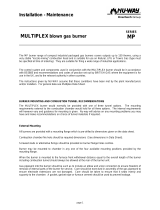
FIGURE 0-1. Firing Head Assembly w/Flame Rod
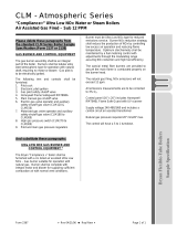
FIGURE 0-2. Firing Head Assembly w/UV Scanner
ELECTRODE
FLAME ROD
SCREW
LOCK WASHER
BAFFLE WELDMENT
STANDOFF
LOCK WASHER
ORIFICE PLATE
SPRING PIN
ELECTRODE
SPRING PIN
NUT
LOCK WASHER
SCREW
UV SCANNER
ORIFICE PLATE
LOCK WASHER
STANDOFF
BAFFLE WELDMENT
LOCK WASHER
SCREW


750-370
ProFire Q Series Manual
i
Q Series
Table of Contents
CHAPTER 1 Introduction 1-1
1.1 — Overview 1-1
1.2 — Description 1-1
1.3 — Operating Controls 1-2
1.3.1 — Control Panel 1-2
1.3.2 — Flame Safeguard Controls 1-2
1.3.3 — Firing Rate Controls for Modulating Burners 1-2
1.4 — Combustion Air Handling System 1-2
1.5 — Firing Head 1-3
1.6 — Gas System 1-3
1.6.1 — Main Gas Train Components 1-4
1.6.2 — Pilot Gas Train Components 1-5
1.6.3 — Operation 1-5
CHAPTER 2 Installation 2-1
2.1 — Application 2-1
2.2 — Draft Conditions 2-1
2.3 — Combustion Air Supply 2-1
2.4 — Combustion Chamber Recommendations 2-2
2.5 — Installation 2-3
2.5.1 — Support Bracket Installation 2-4
2.6 — Packaging Plastic Refractory Around Oven (If Dry Oven is Supplied) 2-5

ii
750-370
ProFire Q Series Manual
2.7 — Gas Piping 2-5
2.8 — Installation Checklist 2-5
CHAPTER 3 Operation 3-1
3.1 — Preparations for Starting 3-1
3.1.1 — Firing Preparations for Gas Burners 3-1
3.1.2 — Burner Settings 3-2
3.1.3 — Combustion Settings 3-2
3.1.4 — Test Equipment 3-3
3.2 — Ignition Adjustment 3-3
3.3 — Startup Sequence 3-3
3.4 — Automatic Shutdown 3-4
3.5 — Manual Shutdown 3-4
3.6 — Safety Shutdown 3-4
3.7 — Startup and Operating 3-5
3.7.1 — Gas Burners (Bubble Test) 3-5
3.7.2 — Burners Designed for On-Off Operation 3-6
3.7.3 — Burners Designed for Low-High-Low Operation 3-6
3.7.4 — Burners Designed for Modulation Operation 3-7
3.9 — Normal Operation 3-9
3.10 — Shutdown 3-10
CHAPTER 4 Adjustments 4-1
4.1 — Overview 4-1
4.2 — Combustion Adjustment on Gas 4-1
4.2.1 — Stack Temperature 4-1
4.2.2 — Gas Adjustments 4-2
4.2.3 — Honeywell V48A Gas Valve Adjustment 4-2
4.3 — Electrical Interference Test 4-2
4.4 — Gas System 4-2
4.4.1 — Gas Pressure 4-2

750-370
ProFire Q Series Manual
iii
4.4.2 — Gas Flow 4-2
4.4.3 — Direct Spark Ignition Flame Adjustment 4-3
4.4.4 — Main Gas Pressure Regulator 4-3
4.4.5 — Low Gas Pressure Switch 4-3
4.4.6 — High Gas Pressure Switch 4-3
4.4.7 — Gas Combustion Adjustment 4-3
4.5 — Parallel Positioning Adjustment 4-4
CHAPTER 5 Maintenance 5-1
5.1 — Overview 5-1
5.2 — Control System 5-1
5.2.1 — Programming Control 5-2
5.3 — Impeller 5-2
5.4 — Firing Head Inspection 5-2
5.5 — Air Filter Inspection 5-2
5.6 — Ignition Electrode & Flame Rod 5-3
5.7 — Flame Scanner 5-3
5.8 — Firing Rate Controls 5-3
5.9 — Burner Mounting Inspection 5-4
5.10 — Gas System 5-4
5.10.1 — Motorized Main Gas Valves 5-4
5.10.2 — Solenoid Valves 5-4
5.11 — Electrical System 5-4
5.11.1 — Electric Motors 5-4
5.12 — Extended Shutdown 5-5
5.13 — Recommended Maintenance Schedule 5-5

iv
750-370
ProFire Q Series Manual
CHAPTER 6 Troubleshooting 6-1
6.1 — Awareness 6-1
6.2 — Emergency Shutdown 6-2
6.3 — Problem/Possible Causes 6-3
STARTUP/SERVICE REPORT
WARRANTY POLICY

750-370
ProFire Q Series Manual
1-1
CHAPTER 1 Introduction
1.1 — Overview
Q series burners are completely assembled, wired, and tested at the factory.
The operator must be familiar with the individual functioning of all controls to understand the operations and
procedures described in this manual.
1.2 — Description
The Q series burners are forced draft type burners. All burners feature direct spark ignition. The burner operates with
either on-off, low-high-low, or full modulation. For modulation burners, refer to the LMV37 manual for changing from
automatic fully modulated firing to manually set firing at any desired rate between minimum and maximum. Fully
modulated burners include additional safeguards to assure that the burner always returns to the minimum firing position
for ignition.
Q series burners are designed for automatic, unattended operation except for periodic inspection and maintenance. The
control panel components require little attention except for occasional cleaning.
Only factory authorized burner service personnel should start up, adjust, or service this equipment.
Burner air, fuel metering valves and positioning motors have not been pre-set by the factory for proper combustion and must
be set by a qualified and authorized technician. Failure to follow this procedure could result in property damage and
personal injury.
!
Caution
!
Warning

Introduction
1-2
750-370
ProFire Q Series Manual
1.3 — Operating Controls
1.3.1 — Control Panel
The control panel contains a flame safeguard programming control, load relay, power supply (where applicable), fusing
and terminal strips mounted internally on a panel sub-base. Lights and switches are mounted externally on the panel.
The modulation burner has an external display mounted on the panel.
1.3.2 — Flame Safeguard Controls
The flame safeguard programmer incorporates a flame sensing cell (scanner) or flame rod to shut down the burner in
the event of ignition flame or main flame failure. Other safety controls shut down the burner based on sequence of
operation as shown in the manufacturer’s flame safeguard manual.
1.3.3 — Firing Rate Controls for Modulating Burners
Burner input is fully modulated between low fire and high fire on boiler demand. The firing rate is controlled by the
linkageless control system. The combustion air flow is controlled by the blower speed. The gas is controlled by a
butterfly valve. The servo rotates 90º from low to high position.
1.4 — Combustion Air Handling System
The combustion air handling system consists of two major components:
Component Details
Fusing Control circuit and motor load fusing.
Modulation Display
(Modulation Burner Only)
AZL display is used for commissioning LMV37 control and for automatic or
manual firing rate control, reset lockout and fault history.
Signal Lamps
a) POWER (white): Illuminates when the control circuit is energized (powered).
b) IGNITION (amber): Illuminates when the ignition transformer is powered.
c) FUEL (green): Illuminates when the main fuel valve or valves are energized (open).
d) FAILURE (red): Illuminates when the flame safeguard system fails to detect main
flame.
View Window
Window provides visual indication of LED display on the flame safeguard.
Read the flame safeguard manual and fully understand its contents before attempting to operate this equipment. Failure to
do so may result in serious personal injury or death.
Component Details
DC(EC) Motor Full speed modulation with Pulse Width Modulation signal input rated
voltage 24VDC, 115VAC
DC Pulse Width Modulation Blower speed controlled by UGB board for LHL burners or LMV37 (See
LMV37 manual for details) for modulating burners.
!
Warning

750-370
ProFire Q Series Manual
1-3
Introduction
1.5 — Firing Head
Access to the firing head is provided by the side access panel. A flame rod and direct spark is standard on all burners
and a UV scanner is available as an option.
FIGURE 1-1. Burner Housing
1.6 — Gas System
Gas is introduced into the combustion zone from a circular manifold through multiple ports in the manifold. The firing
rate is regulated by a main gas regulator and blower inlet choke plate for on-off applications. For full modulation the
fuel metering valve is actuated by the servo. The LMV37 regulates the gas flow in proportion to fan speed which is also
controlled by the LMV37. For low-high-low operation, the gas flow is controlled by the ratio-gas regulator valve. The
ratio regulator regulates the gas flow in proportion to the air pressure. Depending upon specific requirements, safety
shutoff main gas valves are provided for installation in the gas train upstream of the control valves. Safety shutoff gas
valves are wired into the programming control to automatically open and close at the proper time in the operating
sequence.
ELECTRODE
BURNER HOUSING
FLAME ROD
ORIFICE PLATE
BAFFLE PLATE
GAS MANIFOLD
COVER
750-00509-000

Introduction
1-4
750-370
ProFire Q Series Manual
1.6.1 — Main Gas Train Components
Depending upon the requirements of the regulating authority, the gas control system and gas train may consist of some,
or all, of the following items:
FIGURE 1-2. Main Gas Train for On-Off Operation (Q6-037 to Q8-250)
FIGURE 1-3. Main Gas Train for Low-High-Low (Q6-037 to Q8-250)
Component Description
Gas Volume Valve The butterfly-type valve is positioned by the actuator and controls the rate of
flow of the gas.
Main Gas Valves Electrically operated safety shutoff valve(s) that open to admit gas to the
burner. Standard U.L. burners include:
• One solenoid gas valve and one diaphragm gas valve.
Main Gas Regulator Regulates gas train pressure to specified pressure required at inlet to the gas
train. Input is set my the main gas pressure regulator adjustment.
Main Gas Cocks For manual shutoff of the gas supply upstream of the pressure regulator. A
second shutoff cock downstream of the main gas valve(s) provides a means
of testing for leakage through the gas valve(s).
Ratio-Regulator Valve Controls the rate of flow of gas in proportion to the air pressure
750-00515-000
LEAK
TEST
VALVE
GAS
VALVE
GAS
VALVE
(OPTIONAL
MOTORIZED
FOR
VENTLESS)
SHUTOFF
VALVE
HIGH
GAS
PRESSURE
SWITCH
LOW
GAS
PRESSURE
SWITCH
REGULATOR
SHUTOFF
VALVE
LEAK TEST PORTS
750-00515-000
HIGH
GAS
PRESSURE
SWITCH
LOW
GAS
PRESSURE
SWITCH
REGULATOR
SHUTOFF
VALVE
GAS
VALVE
LEAK
TEST
VALVE
VARIABLE
AIR/GAS
RATIO CONTROL
W/SOLENOID
VALVE
SHUTOFF
VALVE
LEAK TEST PORTS
/