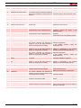
Riello RLS 28 TC LP FS1 1/220/60 220/60 Installer Manual
- Category
- Fireplaces
- Type
- Installer Manual

Installation, use and maintenance instructions
20165123 (2) - 04/2022
Dual fuel light oil/gas burners
Two stage operation
CODE MODEL TYPE
20159362 RLS 28 684 T80
20159364 RLS 50 686 T80
GB

Translation of the original instructions

1 20165123
GB
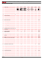
Contents
1 Declarations................................................................................................................................................................................ 3
2 Information and general warnings............................................................................................................................................ 4
2.1 Information about the instruction manual .................................................................................................................... 4
2.2 Guarantee and responsibility....................................................................................................................................... 5
3 Safety and prevention................................................................................................................................................................ 6
3.1 Introduction.................................................................................................................................................................. 6
3.2 Personnel training ....................................................................................................................................................... 6
4 Technical description of the burner ......................................................................................................................................... 7
4.1 Burner designation ...................................................................................................................................................... 7
4.2 Models available.......................................................................................................................................................... 7
4.3 Technical data............................................................................................................................................................. 8
4.4 Electrical data.............................................................................................................................................................. 8
4.5 Maximum dimensions.................................................................................................................................................. 9
4.6 Burner equipment........................................................................................................................................................ 9
4.7 Firing rates ................................................................................................................................................................ 10
4.8 Test boiler.................................................................................................................................................................. 11
4.9 Burner description ..................................................................................................................................................... 12
4.10 Control box RFGO-A22............................................................................................................................................. 14
4.11 Servomotor (LKS 210 ...)........................................................................................................................................... 15
5 Installation ................................................................................................................................................................................ 16
5.1 Notes on safety for the installation ............................................................................................................................ 16
5.2 Handling .................................................................................................................................................................... 16
5.3 Preliminary checks .................................................................................................................................................... 16
5.4 Operating position ..................................................................................................................................................... 17
5.5 Preparing the boiler................................................................................................................................................... 17
5.6 Access to head internal part...................................................................................................................................... 18
5.7 Electrode positions.................................................................................................................................................... 18
5.8 Nozzle installation ..................................................................................................................................................... 19
5.9 Combustion head adjustment.................................................................................................................................... 20
5.10 Light oil supply........................................................................................................................................................... 21
5.11 Pump......................................................................................................................................................................... 23
5.12 Gas supply ................................................................................................................................................................ 24
5.13 Electrical connections................................................................................................................................................ 27
5.14 Calibration of the thermal relay ................................................................................................................................. 29
5.15 Motor rotation ............................................................................................................................................................ 29
6 Start-up, calibration and operation of the burner ................................................................................................................. 30
6.1 Notes on safety for the first start-up .......................................................................................................................... 30
6.2 Adjustments prior to ignition (light oil) ....................................................................................................................... 30
6.3 Burner ignition (light oil)............................................................................................................................................. 30
6.4 Adjustments prior to ignition (gas)............................................................................................................................. 31
6.5 Burner start-up (gas) ................................................................................................................................................. 31
6.6 Burner ignition ........................................................................................................................................................... 31
6.7 Burner adjustment (gas)............................................................................................................................................ 32
6.8 Servomotor adjustment ............................................................................................................................................. 33
6.9 Pressure switch adjustment ...................................................................................................................................... 34
6.10 Operation sequence of the burner............................................................................................................................. 35
6.11 Final checks (with burner operating) ......................................................................................................................... 36

20165123 2
GB
Contents
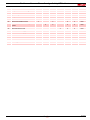
7 Maintenance ..............................................................................................................................................................................37
7.1 Notes on safety for the maintenance .........................................................................................................................37
7.2 Maintenance programme ...........................................................................................................................................37
7.3 Opening the burner ....................................................................................................................................................40
7.4 Closing the burner......................................................................................................................................................40
8 LED indicator and special function.........................................................................................................................................41
8.1 Description of LED lamps ..........................................................................................................................................41
8.2 Check mode function .................................................................................................................................................41
8.3 Flame control lock-out or emergency stop condition .................................................................................................41
8.4 LED lamps: burner operating status ..........................................................................................................................42
9 Problems - Causes - Remedies signalled by LED indicators ...............................................................................................43
A Appendix - Accessories ...........................................................................................................................................................48
B Appendix - Electrical panel layout...........................................................................................................................................49

3 20165123
GB
Declarations
Declaration of Conformity in accordance with ISO / IEC 17050-1
These products are in compliance with the following Technical Standards:
• EN 12100
•EN 676
•EN 267
According to the European Directives:
MD 2006/42/EC Machine Directive
LVD 2014/35/EU Low Voltage Directive
EMC 2014/30/EU Electromagnetic Compatibility
The quality is guaranteed by a quality and management system certified in accordance with ISO 9001:2015.
1 Declarations

20165123 4
GB
Information and general warnings
2.1 Information about the instruction manual
2.1.1 Introduction
The instruction manual supplied with the burner:
is an integral and essential part of the product and must not
be separated from it; it must therefore be kept carefully for
any necessary consultation and must accompany the burner
even if it is transferred to another owner or user, or to
another system. If the manual is lost or damaged, another
copy must be requested from the Technical Assistance
Centre of the area;
is designed for use by qualified personnel;
offers important indications and instructions relating to the
installation safety, start-up, use and maintenance of the
burner.
Symbols used in the manual
In some parts of the manual you will see triangular DANGER
signs. Pay great attention to these, as they indicate a situation of
potential danger.
2.1.2 General dangers
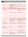
The dangers can be of 3 levels, as indicated below.
2.1.3 Other symbols
Abbreviations used
Ch. Chapter
Fig. Figure
Page Page
Sec. Section
Tab. Table
2 Information and general warnings
DANGER
Maximum danger level!
This symbol indicates operations which, if not
carried out correctly, cause serious injury, death
or long-term health risks.
ATTENTION
This symbol indicates operations which, if not
carried out correctly, may cause serious injury,
death or long-term health risks.
CAUTION
This symbol indicates operations which, if not
carried out correctly, may cause damage to the
machine and/or injury to people.
DANGER
DANGER: LIVE COMPONENTS
This symbol indicates operations which, if not
carried out correctly, lead to electric shocks with
lethal consequences.
DANGER: FLAMMABLE MATERIAL
This symbol indicates the presence of flammable
materials.
DANGER: BURNING
This symbol indicates the risks of burns due to
high temperatures.
DANGER: CRUSHING OF LIMBS
This symbol indicates the presence of moving
parts: danger of crushing of limbs.
WARNING: MOVING PARTS
This symbol indicates that you must keep limbs
away from moving mechanical parts; danger of
crushing.
DANGER: EXPLOSION
This symbol signals places where an explosive
atmosphere may be present. An explosive
atmosphere is defined as a mixture - under
atmospheric conditions - of air and flammable
substances in the form of gases, vapours, mist or
dust in which, after ignition has occurred,
combustion spreads to the entire unburned
mixture.
PERSONAL PROTECTION EQUIPMENT
These symbols indicate the equipment that must
be worn and kept by the operator for protection
against threats against safety and/or health while
at work.
OBLIGATION TO ASSEMBLE THE COVER
AND ALL THE SAFETY AND PROTECTION
DEVICES
This symbol signals the obligation to reassemble
the cover and all the safety and protection devices
of the burner after any maintenance, cleaning or
checking operations.
ENVIRONMENTAL PROTECTION
This symbol gives indications for the use of the
machine with respect for the environment.
IMPORTANT INFORMATION
This symbol indicates important information that
you must bear in mind.
This symbol indicates a list.

5 20165123
GB
Information and general warnings
2.1.4 Delivery of the system and the instruction
manual
When the system is delivered, it is important that:
the instruction manual is delivered to the user by the system
manufacturer, with the recommendation to keep it in the
room where the heat generator is to be installed.
The instruction manual shows:
– the serial number of the burner;
– the address and telephone number of the nearest
Assistance Centre;
The system supplier must carefully inform the user about:
– the use of the system;
– any further tests that may be required before activating the
system;
– maintenance, and the need to have the system checked at
least once a year by a representative of the manufacturer
or another specialised technician.
To ensure a periodic check, the manufacturer
recommends the drawing up of a Maintenance Contract.
2.2 Guarantee and responsibility
The manufacturer guarantees its new products from the date of
installation, in accordance with the regulations in force and/or the
sales contract. At the moment of the first start-up, check that the
burner is integral and complete.
In particular, the rights to the guarantee and the responsibility will
no longer be valid, in the event of damage to things or injury to
people, if such damage/injury was due to any of the following
causes:
incorrect installation, start-up, use and maintenance of the
burner;
improper, incorrect or unreasonable use of the burner;
intervention of unqualified personnel;
carrying out of unauthorised modifications on the equipment;
use of the burner with safety devices that are faulty,
incorrectly applied and/or not working;
installation of untested supplementary components on the
burner;
powering of the burner with unsuitable fuels;
faults in the fuel supply system;
continuation of use of the burner when a fault has occurred;
repairs and/or overhauls incorrectly carried out;
modification of the combustion chamber with inserts that
prevent the regular development of the structurally
established flame;
insufficient and inappropriate surveillance and care of those
burner components most likely to be subject to wear and
tear;
use of non-original components, including spare parts, kits,
accessories and optional;
force majeure.
The manufacturer furthermore declines any and every
responsibility for the failure to observe the contents of this
manual.
.........................................................................................
.........................................................................................
.........................................................................................
.........................................................................................
ATTENTION
Failure to observe the information given in this
manual, operating negligence, incorrect
installation and carrying out of non authorised
modifications will result in the annulment by the
manufacturer of the guarantee that it supplies with
the burner.

20165123 6
GB
Safety and prevention
3.1 Introduction
The burners have been designed and built in compliance with
current regulations and directives, applying the known technical
safety rules and envisaging all the potential danger situations.
It is necessary, however, to bear in mind that the imprudent and
clumsy use of the equipment may lead to situations of death risk
for the user or third parties, as well as the damaging of the burner
or other items. Inattention, thoughtlessness and excessive
confidence often cause accidents; the same applies to tiredness
and sleepiness.
It is a good idea to remember the following:
The burner must only be used as expressly described. Any
other use should be considered improper and therefore
dangerous.
Specifically:
it can be applied to boilers operating with water, steam,
diathermic oil, and to other uses expressly named by the
manufacturer;
the type and pressure of the fuel, the voltage and frequency of the
electrical power supply, the minimum and maximum deliveries for
which the burner has been regulated, the pressurisation of the
combustion chamber, the dimensions of the combustion
chamber and the ambient temperature must all be within the
values indicated in the instruction manual.
Modification of the burner to alter its performance and
destinations is not allowed.
The burner must be used in exemplary technical safety
conditions. Any disturbances that could compromise safety
must be quickly eliminated.
Opening or tampering with the burner components is not
allowed, apart from the parts requiring maintenance.
Only those parts envisaged by the manufacturer can be
replaced.
3.2 Personnel training
The user is the person, body or company that has acquired the
machine and intends to use it for the specific purpose. He is
responsible for the machine and for the training of the people
working around it.
The user:
undertakes to entrust the machine exclusively to suitably
trained and qualified personnel;
undertakes to inform his personnel in a suitable way about
the application and observance of the safety instructions.
With that aim, the user undertakes to ensure that everyone
knows the use and safety instructions for his own duties;
Personnel must observe all the danger and caution
indications shown on the machine.
Personnel must not carry out, on their own initiative,
operations or interventions that are not within their province.
Personnel must inform their superiors of every problem or
dangerous situation that may arise.
The assembly of parts of other makes, or any modifications,
can alter the characteristics of the machine and hence
compromise operating safety. The manufacturer therefore
declines any and every responsibility for any damage that
may be caused by the use of non-original parts.
In addition:
3 Safety and prevention
ATTENTION
The manufacturer guarantees safety and proper
operation only if all burner components are intact
and correctly positioned.
must take all the measures necessary to
prevent unauthorised people gaining access
to the machine;
the user must inform the manufacturer if
faults or malfunctioning of the accident
prevention systems are noticed, along with
any presumed danger situation;
personnel must always use the personal
protective equipment envisaged by legislation
and follow the indications given in this
manual.

7 20165123
GB
Technical description of the burner
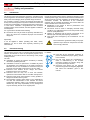
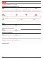
4.1 Burner designation
4.2 Models available
4 Technical description of the burner
Designation Voltage Start-up Code
RLS 28 1/220/60 Direct 20159362
RLS 50 3/220-380/60 Direct 20159364
Class 2 EN267 - Class 3 EN676
Series: R
Size
Fuel: Natural gas
Light oil
Light oil / Methane
Adjustment:
Electrical supply of the system:
3/400/50
3/230/50
Voltage of auxiliaries:
230/50/60
110/50/60
RLS 28 TC
Emission: C11 or... Class 1 EN267 - EN676
C22 or MZ Class 2 EN267 - EN676
C33 or BLU Class 3 EN267 - EN676
3/400/50 230/50/60
BASIC DESIGNATION
EXTENDED DESIGNATION
3N / 400V / 50Hz
3 / 230V / 50Hz
230V / 50-60Hz
110V / 50-60Hz
Heavy oil
E Electronic cam
EV Electronic cam and variable speed (with Inverter)
P Proportional air/gas valve
BP Two stage (light oil) / Proportional valve (gas)
M Mechanical cam
S
L
LS
N
Head: TC Standard head
TL Extended head
C23 or MX
MX Class 1 EN267 - Class 3 EN676
Flame control system:
FS1
FS2
Standard (1 stop every 24 h)
Continuous operation only with the use of a flame detection
electrode (ionisation)

20165123 8
GB
Technical description of the burner
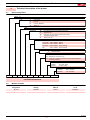
4.3 Technical data
Tab. A
(1) Reference conditions: Ambient temperature 20°C - Gas temperature 15°C - Barometric pressure 1013 mbar - Altitude 0 m a.s.l.
(2) Pressure at test point 7)(Fig. 4 on page 12) with zero pressure in combustion chamber and at maximum burner output.
(3) Sound pressure measured in manufacturer's combustion laboratory, with burner operating on test boiler and at maximum output.
The sound power is measured using the "Free Field" method, required by EN 15036 standard, and according to an “Accuracy: Category 3”
measurement, as described in EN ISO 3746.
4.4 Electrical data
Tab. B
Model RLS 28 RLS 50
Type 684 T80 686 T80
Output (1)
Delivery (1) 2nd Stage kW
kg/h
163 ÷ 325
13.7 ÷ 27.4
290 ÷ 581
24.5 ÷ 49
Min. 1st Stage kW
kg/h
100
8.5
145
12.3
Fuels – Light oil, max. viscosity at 20 °C: 6 mm2/s (1.5 °E - 6 cSt)
– Natural gas: G20 (methane) - G21-G22-G23-G25
– LPG - G30 (propane) - G31 (butane)
Gas pressure at max. output (2) -
Gas: G20/G25/G31 mbar 11/16.2/9.5 14/20.8/10.5
Operation – Intermittent (min. 1 stop in 24 hours)
– Two-stage (high and low flame) and one-stage (all - nothing)
Pump Output at 12 bar
Pressure range
Fuel temperature
kg/h
bar
°c max
67
4 - 18
60
Nozzles number 2
Standard applications Boilers: water, steam, diathermic oil
Ambient temperature °C 0 - 40
Combustion air temperature °C max 60
Noise levels (3) Sound pressure
Sound power dB(A) 68
79
72
83
Weight kg 43 46
Model RLS 28 RLS 50
Electrical power supply V
Hz
220 +/-10%
60 - single-phase ~
220-380 with neutral+/-10%
60 - three-phase ~
Fan motor rpm
V
W
A
3400
220
300
2.2
3400
220-380
550
3.6 -1.8
Fan motor capacitor µF 12.5 -
Pump motor V
W
A
220
90
1
Pump motor capacitor µF 2.5
Ignition transformer V1 - V2
I1 - I2
230 V - 2 x 5 kV
1.9 A - 30 mA
Max. absorbed electric power W max 750 1250
Protection level IP 44

9 20165123
GB
Technical description of the burner
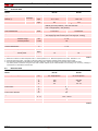
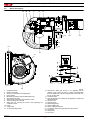
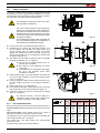
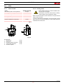
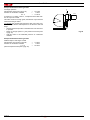
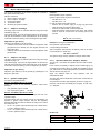
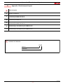
4.5 Maximum dimensions
The dimensions of the burner are given in Fig. 1.
Note that to inspect the combustion head the burner must be
moved backward and turned upward.
The maximum dimension of the burner, without casing, when
open is given by measurement H.
Tab. C
4.6 Burner equipment
Flange for gas train . . . . . . . . . . . . . . . . . . . . . . . . . . . . . . No. 1
Seal for flange . . . . . . . . . . . . . . . . . . . . . . . . . . . . . . . . . . No. 1
Flange fixing screws M 8 x 25 . . . . . . . . . . . . . . . . . . . . . . No. 4
Thermal flange gasket . . . . . . . . . . . . . . . . . . . . . . . . . . . . No. 1
Screws to fix the burner flange to the
boiler: M 8 x 25. . . . . . . . . . . . . . . . . . . . . . . . . . . . . . . . . . No. 4
Cable grommets for electrical connection
(RLS 28 single-phase). . . . . . . . . . . . . . . . . . . . . . . . .No. 5
Cable grommets for electrical wiring
(RLS 50 three-phase). . . . . . . . . . . . . . . . . . . . . . . . . . . . . No. 6
Flexible hoses . . . . . . . . . . . . . . . . . . . . . . . . . . . . . . . . . . No. 2
Nipples for flexible hoses with gaskets. . . . . . . . . . . . . . . . No. 2
Kit for LPG operation . . . . . . . . . . . . . . . . . . . . . . . . . . . . . No. 1
Label for LPG operation . . . . . . . . . . . . . . . . . . . . . . . . . . . No. 1
Instructions . . . . . . . . . . . . . . . . . . . . . . . . . . . . . . . . . . . . . No. 1
Spare parts list . . . . . . . . . . . . . . . . . . . . . . . . . . . . . . . . . . No. 1
Fig. 1
D495
mm ABCDEFGH I LM
RLS 28 476 474 580 191 140 352 164 810 108 168 1”1/2
RLS 50 476 474 580 216 152 352 164 810 108 168 1”1/2

20165123 10
GB
Technical description of the burner
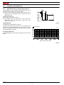
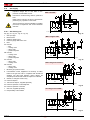
4.7 Firing rates
The burners RLS 28 - 50 can work in two ways: one-stage or two-
stage.
The MAXIMUM OUTPUT is chosen within area A (and B for RLS
50)(Fig. 2). To use also area B (RLS 50), the combustion head
has to be pre-calibrated as shown on page 18.
The MINIMUM OUTPUT must not be lower than the minimum
limit of the diagram:
RLS 28 = 100 kW = 8.5 kg/h
RLS 50 = 145 KW = 12.3 kg/h
ATTENTION
The firing rate value (Fig. 2) has been obtained
considering an ambient temperature of 20 °C, an
atmospheric pressure of 1013 mbar (approx. 0 m
a.s.l.), and with the combustion head adjusted as
shown on page 20.
Pressure in the combustion
chamber - mbar
Fig. 2
RLS 28
Pressure in the combustion
chamber - mbar
Thermal power – kW
RLS 50
Thermal power – kW
D9172

11 20165123
GB
Technical description of the burner
4.8 Test boiler
The burner/boiler combination does not pose any problems if the
boiler is EC approved and its combustion chamber dimensions
are similar to those indicated in the diagram (Fig. 3).
If the burner must be combined with a boiler that has not been EC
approved and/or its combustion chamber dimensions are clearly
smaller than those indicated in the diagram, consult the
manufacturer.
The firing rates were set in relation to special test boilers,
according to EN 676 and EN 267 regulations.
In Fig. 3 you can see the diameter and length of the test
combustion chamber.
Example:
Output 350 Mcal/h (407 kW): diameter 50 cm - length 1.5 m.
Fig. 3
Combustion chamber
m
D497

20165123 12
GB
Technical description of the burner
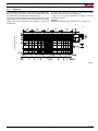
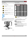
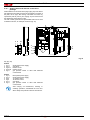
4.9 Burner description
1 Combustion head
2 Ignition electrodes
3 Screw for combustion head adjustment
4 Pipe coupling
5 Minimum air pressure switch (differential type)
6 Air pressure test point
7 Gas pressure test point and head fixing screw
8 Screw securing fan to sleeve
9 Slide bars for opening the burner and inspecting the
combustion head
10 Pump
11 Safety valve
12 1st and 2nd stage valves
13 Servomotor. When the burner is not operating the air
damper is fully closed in order to reduce heat dispersion
from the boiler due to the flue draught which draws air from
the fan suction inlet.
14 OIL/GAS switch
15 Plate prearranged for 4 holes for the passage of hoses and
electrical cables.
16 Air inlet to fan
17 Gas input pipe
18 Boiler fixing flange
19 Flame stability disc
20 Flame inspection window
21 Control box with lockout pilot light and reset button
22 Air damper
23 Pump motor
24 Fan motor
14
21
24
17
16
15
22
23 20 10 11 12 13
19
18
20166791
20166770
Fig. 4
D1118

13 20165123
GB
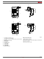
Technical description of the burner
1 One switch for "burner on - off”
one switch for “1st - 2nd stage"
2 Fan motor contactor and thermal relay with reset button
(RLS 50)
3 Motor capacitor (RLS 28)
4 Flame sensor
5LED panel
6 Control box base
7 4-pole socket
8 5-pole socket
9 6-pole socket
10 7-pole socket
11 Ignition transformer
Burner lockout may occur:
CONTROL BOX LOCKOUT:
if the control box 21)(Fig. 4) push-button lights up, it indicates that
the burner is in lockout.
Press the push button to reset.
Fig. 5
4
6
5
1
10
7
9
3
11
24
5
1
10
7
8
6
11
20166771

20165123 14
GB
Technical description of the burner
4.10 Control box RFGO-A22
Important notes
All interventions (assembly and installation operations,
assistance, etc.) must be carried out by qualified personnel.
Before modifying the wiring in the control box connection
area, fully disconnect the system from the power supply
(omnipolar separation).
Protection against electrocution from the control box and all
connected electric components is obtained with the correct
assembly.
Before any intervention (assembly and installation
operations, assistance, etc.), ensure the wiring is in order
and that the parameters are correctly set, then make the
safety checks.
Falls and collisions can negatively affect the safety
functions. In this case, the control box must not be operated,
even if it displays no evident damage.
For safety and reliability, comply with the following
instructions:
– avoid conditions that can favour the development of
condensate and humidity. Otherwise, before switching on
again, make sure that the entire control box is perfectly dry!
– Static charges must be avoided since they can damage the
control box’s electronic components when touched.
Use
The control box is a control and supervision system of medium
and large capacity forced draught burners.
If used with the flame detection electrode the system can operate
continuously whereas, with the use of UV sensors it operates
intermittently with stop and restart request at least once every
24h.
Installation notes
• Make sure that the electrical wiring inside the boiler complies
with national and local safety regulations.
• Do not confuse the powered conductors with the neutral
ones.
• Ensure that spliced wires cannot get into contact with
neighbouring terminals. Use adequate ferrules.
• Arrange the H.V. ignition cables separately, as far as
possible from the control box and the other cables.
• When wiring the unit, make sure that AC 230 V mains voltage
cables are run strictly separate from extra low-voltage cables
to avoid risks of electrical shock hazard.
Technical data
Tab. D
Electrical wiring of the flame detector
It is important for signal transmission to be almost totally free
of any disturbances or loss:
• Always separate the detector cables from the other cables:
– The capacitive reactance of the line reduces the size of the
flame signal.
– Use a separate cable.
• Respect the allowed cable lengths.
• The ionisation probe is not protected against the risk of
electrocution. When connected to the electricity supply, the
ionisation probe must be protected against any accidental
contact.
• Position the ignition electrode and the ionisation probe so
that the ignition spark cannot form an arc on the probe (risk
of electric overcharge).
ATTENTION
To avoid accidents, material or environmental
damage, observe the following instructions!
The control box is a safety device! Avoid opening
or modifying it, or forcing its operation. The
Manufacturer cannot assume any responsibility
for damage resulting from unauthorised work!
Mains voltage AC 230 V -15 % / +10%
Mains frequency 50 / 60 Hz
Primary fuse (external) Refer to the electric
system
Weight approx. 1.1 kg
Power absorption approx. AC 7 VA
Protection level IP40
Safety class II
Environmental conditions
Operation
Climatic conditions
Mechanical conditions
Temperature range
Humidity
DIN EN 60721-3-1
Class 1K2
Class 1M2
-40...+60°C
< 90% RH (non-condensing)
Fig. 6
20152163

15 20165123
GB
Technical description of the burner
4.11 Servomotor (LKS 210 ...)
Important notes
All interventions (assembly and installation operations,
assistance, etc.) must be carried out by qualified personnel.
Before modifying the wiring in the connection area of the
servomotor, fully disconnect the burner control device from
the power supply (omnipolar separation).
To avoid the risk of electrocution, protect the connection
terminals in a suitable manner and correctly fix the cover.
Check the wiring is in order.
Falls and collisions can negatively affect the safety
functions. In this case, the servomotor must not be operated,
even if it displays no evident damage.
Assembly notes
• Check the relevant national safety standards are respected.
• When assembling the servomotor and connecting the
damper, the gears can be disengaged by means of a lever,
allowing the drive shaft to be easily adjusted in both
directions of rotation.
Technical data
Tab. E
ATTENTION
To avoid accidents, material or environmental
damage, observe the following instructions!
Avoid opening, modifying or forcing the
actuators.
MODEL LKS 210 - 10
Operating voltage 200-240V - 50/60 Hz
Switching capacity
of auxiliary and limit switches 10 A/ 250V
Opening time 0-90°, 5 sec.
Firing angle 0 - 90°
Torque 1.5 Nm
Rotation direction Anticlockwise
Weight 0.7 kg
Protection level IP 44
Fig. 7
MV2
0
10
20
30
40
50
60
70
80
90
–
+
S9697

20165123 16
GB
Installation
5.1 Notes on safety for the installation
After carefully cleaning all around the area where the burner is to
be installed, and arranging for the environment to be illuminated
correctly, proceed with the installation operations.
5.2 Handling
The burner packaging includes a wooden platform, it is therefore
possible to handle the burner (still packaged) with a pallet truck
or fork lift truck.
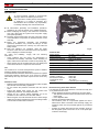
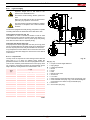
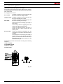
5.3 Preliminary checks
Checking the consignment
Checking the characteristics of the burner
Check the identification label of the burner, showing:
the model (A)(Fig. 8) and type of burner (B);
the year of manufacture, in cryptographic form (C);
the serial number (D);
the data for electrical supply and the protection level (E);
the absorbed electrical power (F);
the types of gas used and the relative supply pressures (G);
the data of the burner's minimum and maximum output
possibilities (H) (see Firing rate).
Warning. The burner output must be within the firing rate of
the boiler;
the category of the appliance/countries of destination (I);
light oil maximum viscosity (L).
5Installation
DANGER
All the installation, maintenance and disassembly
operations must be carried out with the electricity
supply disconnected.
ATTENTION
The installation of the burner must be carried out
by qualified personnel, as indicated in this manual
and in compliance with the standards and
regulations of the laws in force.
DANGER
The combustion air inside the boiler must be free
from hazardous mixes (e.g.: chloride, fluoride,
halogen); if present, it is highly recommended to
carry out cleaning and maintenance more
frequently.
ATTENTION
Burner handling operations can be highly
dangerous if not carried out with the greatest
attention: distance unauthorised personnel, check
integrity and suitability of the means available.
Check also that the area in which you are working
is empty and that there is an adequate escape
area (i.e. a free, safe area to which you can
quickly move if the burner should fall).
During handling, keep the load at no more than
20-25 cm from the ground.
After positioning the burner near the installation
point, correctly dispose of all residual packaging,
separating the various types of material.
CAUTION
Before proceeding with the installation operations,
carefully clean all around the area where the
burner will be installed.
CAUTION
After removing all the packaging, check the
integrity of the contents. In the event of doubt, do
not use the burner; contact the supplier.
The packaging elements (wooden cage or
cardboard box, nails, clips, plastic bags, etc.)
must not be abandoned as they are potential
sources of danger and pollution; they should be
collected and disposed of in the appropriate
places.
ATTENTION
A burner label that has been tampered with,
removed or is missing, along with anything else
that prevents the definite identification of the
burner makes any installation or maintenance
work difficult.
Fig. 8
D9243
R.B.L.
GAS- KAASU
GAZ- AEPIO
0085
RIELLOS.p.A.
I-37045 Legnago (VR)
CE
HEIZÖLFUEL
ABC
EDF
HG
GH
I
L

17 20165123
GB
Installation
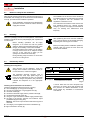
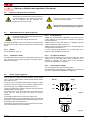
5.4 Operating position
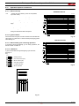
5.5 Preparing the boiler
5.5.1 Boring the boiler plate
Pierce the closing plate of the combustion chamber, as in Fig. 10.
The position of the threaded holes can be marked using the
thermal insulation screen supplied with the burner.
Tab. F
5.5.2 Blast tube length
The length of the blast tube must be selected according to the
indications provided by the manufacturer of the boiler, and in any
case it must be greater than the thickness of the boiler door
complete with its fettling. The range of lengths available, L (mm),
is as follows:
Tab. G
For boilers with front flue passes 13) or flame inversion
chambers, a protection in heat-resistant material 11) must be
inserted between the boiler refractory 12) and the blast tube 10).
This protection must not compromise the extraction of the blast
tube.
For boilers with a water-cooled front piece, a refractory lining 11)-
12)(Fig. 11) is not necessary, unless expressly requested by the
boiler manufacturer.
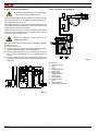
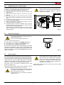
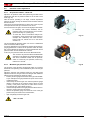
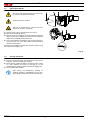
5.5.3 Securing the burner to the boiler
Separate the combustion head from the rest of the burner
(Fig. 11):
disconnect the light oil pipes unscrewing the two unions 4);
remove screw 14) and extract the cover 15);
remove screws 2) from the two slide bars 3);
remove screw 1) and pull the burner back on slide bars 3) by
about 100 mm;
disconnect the wires of the electrodes and then pull the
burner completely off the slide bars, after removing the split
pin from the slide bar 3).
ATTENTION
The burner is set up to operate only in
positions 1, 2, 3 and 4 (Fig. 9).
Installation 1 is preferable, as it is the only
one that allows the maintenance operations
as described in this manual.
Installations 2, 3 and 4 permit operation but
make maintenance and inspection of the
combustion head more difficult.
DANGER
Any other position could compromise the
correct operation of the appliance.
The installation 5 is prohibited for safety
reasons.
Fig. 9
2 3 4 51
D3928
mm ABC
RLS 28 160 224 M 8
RLS 50 160 224 M 8
mm RLS 28 RLS 50
Standard 191 216
Elongated 326 351
Fig. 10
D455
Provide an adequate lifting system.
ATTENTION
The seal between burner and boiler must be
airtight.
Fig. 11
D1121

20165123 18
GB
Installation
5.6 Access to head internal part
In order to reach inside the combustion head (Fig. 12) proceed as
follows:
remove the screw 1) and the internal part 2).
5.6.1 Combustion head pre-calibration
For the RLS 50 model, check whether the maximum output of the
burner in the 2nd stage is within area A or in area B of the firing
rate. See "Firing rates” on page 10.
– If it is in area A, no intervention is required.
– However, if it is in area B:
Loosen the screws 1)(Fig. 13) and disassemble the blast
tube 2);
Move the fixing point of the rod 3)(Fig. 13) from position A to
position B, thereby drawing back the shutter 4);
Reassemble the blast tube 2)(Fig. 13) and the screws 1)
Once this operation (if necessary) has been carried out, fix the
flange 9)(Fig. 11 on page 17) to the boiler plate, interposing the
insulating gasket 6)(Fig. 11 on page 17) supplied.
Use the 4 screws supplied with the unit, after protecting the
thread with anti-locking product.
The seal between burner and boiler must be airtight.
5.7 Electrode positions
Be careful as some drops of fuel may leak out
during this phase.
Fig. 12
D1122
Fig. 13
D457
ATTENTION
Check that the electrodes are positioned
correctly, as in Fig. 14, complying with the
dimensions indicated.
Fig. 14
D1124
Page is loading ...
Page is loading ...
Page is loading ...
Page is loading ...
Page is loading ...
Page is loading ...
Page is loading ...
Page is loading ...
Page is loading ...
Page is loading ...
Page is loading ...
Page is loading ...
Page is loading ...
Page is loading ...
Page is loading ...
Page is loading ...
Page is loading ...
Page is loading ...
Page is loading ...
Page is loading ...
Page is loading ...
Page is loading ...
Page is loading ...
Page is loading ...
Page is loading ...
Page is loading ...
Page is loading ...
Page is loading ...
Page is loading ...
Page is loading ...
Page is loading ...
Page is loading ...
Page is loading ...
Page is loading ...
Page is loading ...
Page is loading ...
Page is loading ...
Page is loading ...
Page is loading ...
Page is loading ...
Page is loading ...
Page is loading ...
Page is loading ...
Page is loading ...
-
 1
1
-
 2
2
-
 3
3
-
 4
4
-
 5
5
-
 6
6
-
 7
7
-
 8
8
-
 9
9
-
 10
10
-
 11
11
-
 12
12
-
 13
13
-
 14
14
-
 15
15
-
 16
16
-
 17
17
-
 18
18
-
 19
19
-
 20
20
-
 21
21
-
 22
22
-
 23
23
-
 24
24
-
 25
25
-
 26
26
-
 27
27
-
 28
28
-
 29
29
-
 30
30
-
 31
31
-
 32
32
-
 33
33
-
 34
34
-
 35
35
-
 36
36
-
 37
37
-
 38
38
-
 39
39
-
 40
40
-
 41
41
-
 42
42
-
 43
43
-
 44
44
-
 45
45
-
 46
46
-
 47
47
-
 48
48
-
 49
49
-
 50
50
-
 51
51
-
 52
52
-
 53
53
-
 54
54
-
 55
55
-
 56
56
-
 57
57
-
 58
58
-
 59
59
-
 60
60
-
 61
61
-
 62
62
-
 63
63
-
 64
64


Riello RLS 28 TC LP FS1 1/220/60 220/60 Installer Manual
- Category
- Fireplaces
- Type
- Installer Manual
Ask a question and I''ll find the answer in the document
Finding information in a document is now easier with AI
Related papers
-
Riello RLS 130 TC LP FS1 3/208-230/380/60 230/50-60 Installer Manual
-
Riello GAS 4 P/M TC FS1/FS2 1/230/50 230/50-60 Installer Manual
-
Riello BG7.1D 1/230/50 Installer Manual
-
-
-
-
-
-
-
Riello RLS 70 Installation guide
Other documents
-
 ECOFLAM BLU TS 4000.1 PR HT User manual
-
elco VGL06 Operation and Maintenance Manual
-
Aerco MFC 8000 User manual
-
BALTUR TBML 450 LX ME 50Hz Use and Maintenance Manual
-
-
-
-
-
-
