Page is loading ...

1
IMPORTANT:
Go to www.extron.com for the
complete user guide
, installation
instructions, and specifications.
The Extron VNM Enterprise Controller 200 is a dedicated control device for managing large
VN-Matrix systems. The controller allows users to view, manage, and dynamically control
multiple VN-Matrix systems and networked VN-Matrix domains from a single user interface.
This guide provides basic instructions for an experienced installer to congure and operate a single VNM Enterprise
Controller200 in a basic VN-Matrix system.
NOTE: See the VNM Enterprise Controller 200 User Guide, VN-Matrix 200 Series User Guide, VN-Matrix 225 Series User
Guide, VN-Matrix 250 User Guide, VN-Matrix 300 User Guide, and the VN-Matrix 325 User Guide for complete installation,
network configuration, and mounting information.
Step 2 — Cable the Controller
0.5A MAX~
100 - 240V
50 - 60Hz~
HDMI
RGBHV
GTx
RS-232
REMOTE
Rx
A
B
3
1
2
DISPLAYPORT
2
RESET
POWER
OUTPUTS
LANUSB
OUTPUTS
VNM EC 200
VNM ENTERPRISE CONTROLLER
CONFIG
PWR
SSD
LAN
A
LAN
B
A B C D E F G H IJ
K L
Rear Panel Front Panel
M
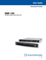
Figure 1. VN Matrix Enterprise Controller 200, Rear Panel
A
AC power — IEC connector. Standard AC power: 100 to 240 VAC, at 50 to 60 Hz.
B
DisplayPort video output — Connect a compatible DisplayPort display for troubleshooting.
C
HDMI video output — Connect a compatible HDMI display for troubleshooting.
D
USB ports — Two USB port connections for one mouse and one keyboard.
E
Ethernet connector — LAN A for connection to a standard LAN.
F
Ethernet connector — LAN B for connection to a second VNM Enterprise Controller 200 (redundant operation only).
G
VGA Connector — One congurable analog output 15-pin HD (VGA) connector for use in troubleshooting.
H
Serial Connector — Provides remote control using RS-232 and the High Level Interface (HLI) command control protocol that
allows users to interface a third party control system with the devices on a VN-Matrix network.
I
Reset button and LED — The VNM Enterprise Controller 200 has two reset modes to restore conguration settings or all
settings back to factory defaults. The LED indicates the desired reset mode, and provides the reset status during the reset
operation. For information on using the reset mode, see the VN Matrix Enterprise Controller 200 User Guide.
J
Recessed power button — Press once to initiate a safe shutdown of the system.
0.5A MAX~
100 - 240V
50 - 60Hz~
HDMI
RGBHV
GTx
RS-232
REMOTE
Rx
A
B
3
1
2
DISPLAYPORT
2
RESET
POWER
OUTPUTS
LANUSB
OUTPUTS
VNM EC 200
VNM ENTERPRISE CONTROLLER
CONFIG
PWR
SSD
LAN
A
LAN
B
A B C D E F G H IJ
K L
Rear Panel Front Panel
M
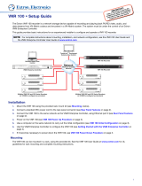
Figure 2. VN Matrix Enterprise Controller 200, Front Panel
K
USB mini-B config port — Connect to a PC for Simple Instruction Set (SIS™) control.
L
Status LEDs — Four LEDs provide the status of the VNM EC 200.
• Network Activity LED (A) — Lights steadily when a network link is established. Blinks to indicate activity.
• Network Activity LED (B) — Lights steadily when a network link is established. Blinks to indicate activity.
• Drive Activity LED — Blinks to indicate drive activity.
• Power LED — Lights when the controller is powered.
M
Solid State Drive (SSD) — This removable drive holds the operating system (OS) and software required for operation.
Step 1 — Mount the VNM Enterprise Controller 200
Disconnect power to the VNM Enterprise Controller 200 and turn off all devices that will be connected to it. The controller is
housed in a half rack wide, 11.5 inches deep, 1U high metal enclosure that can be rack mounted or placed on a table (with the
provided rubber feet attached). Select a suitable mounting option and location, and follow the instructions provided with the
mounting kit.

2
VN Matrix EC 200 • Setup Guide (Continued)
Initial EC 200 Installation and Configuration
Step 1 — Determine the Network Settings
Before any device is connected to a network, the default network settings of each device must be changed. On an existing
network, check with the network administrator for a range of available IP addresses.
On a closed network used exclusively for VN-Matrix devices, it is recommended to use addresses within the range of
192.168.254.1 through 192.168.254.253 with a subnet mask of 255.255.255.0.
Figure 3 shows an addressing scheme for a simple system containing a VNM Enterprise Controller, an encoder, and a decoder.
LAN -1
LAN -2
STATUS
RGB/DVI OVER IP
VN-MATRIX 200 SERIES
LAN -1
LAN -2
STATUS
RGB/DVI OVER IP
VN-MATRIX 200 SERIES
PC (Source)
Display
VNM 225 (Encoder)
Local IP Address: 192.168.254.101
Controller IP Address: 192.168.254.254
Local IP Address: 192.168.254.102
Controller IP Address: 192.168.254.254
Local IP Address: 192.168.254.254
Controller IP Address: 192.168.254.254
VNM 225 (Decoder)
RGB
or
DVI
DVI
RS-232 RS-232
Browser User
Control
ss
:
1
92
.
168
.
25
4
.
2
54
Controller
IP
Addr
L
oca
l
IP
Add
ress: 1
92
.1
68
.
2
54.
2
5
4
C
ontroller IP Address: 192.168.254.25
4
VNM EC 200
VNM ENTERPRISE CONTROLLER
CONFIG
PWR
SSD
LAN
A
LAN
B
VNM EC 200 (System Controller)
Internet/
Network
Figure 3. VN Matrix System
Map your system IP addresses for all connected devices and write them down.
Step 2 — Install and Configure the VN-Matrix Devices
See the setup guide included with each device. Connect each VN-Matrix device to the control PC, one at a time, and power the
device on. Congure the network settings according to your IP address map. DO NOT use 192.168.254.254. The system above
can be used as a guide for conguring network settings.
Once the new IP address for a device is entered, it can remain connected to the LAN and powered on.
Step 3 — Connect the VNM Enterprise Controller 200 to the VN-Matrix Network
On the rear panel of the EC200, connect the network to LAN A (see figure 1,
E
on the previous page) using a Category (CAT) 6
twisted pair cable.
NOTE: The LAN B Ethernet connector is used only if a secondary (redundant) VNM Enterprise Controller 200 is installed. For
information on how to set up a secondary controller, see the VNM Enterprise Controller 200 User Guide.
Step 4 — Power on the VNM Enterprise Controller 200
Connect a standard IEC power cord to the controller and to a 100 to 240 VAC, 50 Hz or 60 Hz power source. The controller
powers up when an AC source is connected.
Step 5 — Configure the Network Settings of the VNM Enterprise Controller 200
The VNM Enterprise Controller 200 is precongured with the following network settings:
IP address: 192.168.254.254
Subnet mask: 255.255.255.0
NOTE: With these settings, the VN-Matrix devices must use IP addresses within the range of 192.168.254.1 through
192.168.254.253 and the same subnet mask. The example in figure 3 (above) uses the default settings of the VNM EC200.

3
Use the following procedure to change the network settings of the VNM Enterprise Controller 200, if necessary.
1. Congure the network settings of a control PC to use an IP address within 192.168.254.1 to 192.168.254.253
and a subnet mask of 255.255.255.0. Connect the control PC to the VN-Matrix network.
2. Open a web browser on the control PC and enter the IP address of the VNM Enterprise Controller 200 in the address bar (for
example, http://192.168.254.254). The login screen opens (see gure 4).
Figure 4. Enterprise Controller Login Page
3. Enter the appropriate username and password.
NOTE: The default user name is admin. The default password is admin. Entries are case sensitive.
4. Click Login or press the <Enter> key. The Web-based User Interface defaults to the Devices page (see gure 5,
1
).
11
Figure 5. Devices Page
5. On the default Devices page, click the Conguration tab (see gure 6,
1
).
The Conguration page opens.
222
33
3
44
4
11
1
Figure 6. Configuration Page
09-17-2015 GF: New screen shots from Simon placed in Ax1.

4
VN Matrix EC 200 • Setup Guide (Continued)
6. On the Conguration page, click the Network link (see figure 6,
2
on the previous page).
7. Change the IP Address, Netmask, and Gateway elds (
3
) as necessary.
NOTE: The MTU field does not require changing.
8. Click Apply Changes (
4
) to save the conguration. The controller restarts. After the restart, the network settings are
properly congured.
9. On the control PC, congure the IP address so that it is within the address range of the VNM Enterprise Controller 200.
NOTE: Perform this step only if the IP address of the controller uses a network prefix or subnet other than
192.168.254.xxx.
10. If necessary, restart the control PC to save the conguration.
Step 6 — Configure the VNM EC 200 as the System Controller
1. Log in to the controller and click the Conguration tab (see gure 7,
1
).
The Conguration page opens.
11
3
3
2
2
5
5
4
4
6
6
7
7
Figure 7. System Configuration Page
2. On the Conguration page, click the System cong link (see gure 7,
2
).
3. From the Protocol drop-down list (
3
), select the transport protocol for the VN-Matrix system.
NOTES:
• The default transport protocol is unicast.
• Unicast supports up to four simultaneous streams from a single encoder.
• Multicast supports a single stream that can be used by multiple decoders. This protocol requires a network that
supports Internet Group Management Protocol (IGMP) snooping for correct operation.
• TCP supports a single stream from a single encoder.
4. Ensure that the Clean Switch option (
4
) is enabled (checked) to smooth transitions when switching between
VN-Matrix 200/225/250 device streams.
NOTE: VN-Matrix 300 / 325 devices do not support Clean Switch and ignore this setting.
5. If necessary, highlight all IP addresses and click Delete (
5
) to clear the Controllers: eld.
6. Click Add (
6
) and enter the correct IP address of the VNM EC 200 previously created (see Step 5 — Configure the Network
Settings of the VNM Enterprise Controller 200 on page2) into the window that opens and click OK.
7. Click Apply Changes (
7
) to save the conguration. The VNM Enterprise Controller 200 restarts and is assigned as the
system controller.

55
8. Refresh the browser to activate and view the changes.
9. If necessary, log in, then click the Conguration tab (see gure 8,
1
).
The Conguration page opens.
11
2
2
3
3
4
4
Figure 8. Role Configuration Page
10. On the Conguration page, click Role (
2
).
11. From the Device Mode drop-down list, select singleton (
3
).
NOTE: This guide details how to set up a VN-Matrix system using a single VNM EC 200. For information on how to set
up a secondary controller, see the VNM Enterprise Controller 200 User Guide.
12. Click Apply Changes (
4
) to save the conguration.
13. Refresh the browser to activate and view the changes.
Step 7 — Assign VN-Matrix 200 / 225 / 300 / 325 Devices as Encoders and Decoders
1. If necessary, log in, then click the Devices tab (see gure 9,
1
).
The Devices page opens.
11
2
2
4
4
3
3
Figure 9. Devices Page — Mode Selection Menu
2. Click the box in the same row as the desired device. The row highlights and the box is checked (see gure 9,
2
).
3. Select Mode (
3
) from the menu at the bottom of the page. The Device Mode dialog opens (
4
).
4. Determine the functionality of the device and choose Encoder or Decoder (
4
) as appropriate.
NOTE: Choosing a mode or toggling a device between an encoder and a decoder can take a few seconds after the
selection is made.
5. Repeat this procedure for other devices as necessary.

6
VN Matrix EC 200 • Setup Guide (Continued)
Configure the Connected VN-Matrix Devices
Once the VN-Matrix devices are assigned as encoders and decoders in the VN-Matrix network, no further conguration is
required. However, the individual devices on a VN-Matrix network can be further congured using the controller Web-based user
interface.
The following sections summarize how to congure devices using the VNM Enterprise Controller 200. For detailed information
click on the question mark icon (see gure at right,
1
) located on
each of the menu pop-up pages, or see the
VNM Enterprise Controller 200 User Guide and the
VN-Matrix 225
/
250
/
300
/
325 User Guides.
Encoder Configuration
1. Log in to the controller, then click the Devices tab (see figure 9,
1
on the previous page). The Devices page opens.
2. Select an encoder (see figure 9,
2
). At the bottom of the page, several menus are now available (see gure 10).
Actions:
UpgradeCompression Peripherals LicenseInfo Connections Configure Fo rmat Mode Misc Group
Figure 10. Encoder Devices Configuration Menu
NOTE: The menu options change depending on the device selected for configuration.
4. Select the following menus and congure the settings as necessary to allow for optimal encoder streaming.
• Congure — Sets global parameters specic to selected VN-Matrix units. Use this window to change the device name
and congure the operating mode of the device.
• Format — Use this window to view information about the incoming source, make adjustments to the signal, and set
EDID options.
• Compression — Use this window to adjust the amount of compression that is applied to the stream.
5. Repeat this procedure for other encoders as necessary.
Decoder Configuration
1. Click the Devices tab (see figure 9,
1
on the previous page). The Devices page opens.
2. Select a decoder (see figure 9,
2
). At the bottom of the page, several menus are now available (see gure 11).
Actions:
UpgradePeripherals LicenseInfo Connections Configure Format Mode Misc Group
Figure 11. Decoder Devices Configuration Menu
NOTE: The menu options change depending on the device selected for configuration.
3. Select the following menus and congure the settings as necessary to allow for optimal decoder streaming.
• Congure — Sets global parameters specic to selected VN-Matrix units. Use this window to change the device name
and congure the operating mode of the device.
• Format — Use this window to adjust the format of the signal being output to a display.
4. Repeat this procedure for other decoders as necessary.
11

7
Web-based User Interface Control Options
This section details control options that are available using the Web-based user interface. For more information on all available
control options, see the VNM Enterprise Controller 200 User Guide.
Using the Switcher Page
The Switcher page assigns encoders (sources) to decoders (displays). This allows the user to control streaming throughout the
entire system using a single page. Use the following procedure to congure the Switcher page.
1. Click on the Switcher link located at the top right of the web page. The Switcher page opens (see gure 12).
11
2
2
3
3
4
4
Figure 12. Switcher Page
2. From the Sources column, click on an encoder (see gure 12,
1
).
3. From the Displays column, click on a decoder (
2
).
4. Click Take (
3
). A connection is created between the selected encoder and decoder. Figure 12 shows that Encoder1 is
streaming media to Decoder3.
5. Repeat this procedure to create other connections as necessary.
NOTE: To remove a connection, select a connection (from the Connections column) and click Break Connection.
To remove all connections, select a connection and click Break All Connections.
6. If audio data is present within the stream, click on the edit link located at the top right of the
Switcher page (see gure 12,
4
) and select the Switch audio with video option (see gure
at right,
1
). This keeps the audio and video data together when you are creating connections.
Updating the VNM Enterprise Controller 200 License
Updating the license of the VNM Enterprise Controller 200 is sometimes necessary to enable certain features of the system.
Use the following procedure to update the license.
1. Click the Conguration tab (see gure 13,
1
). The Conguration page opens (you may need to log in).
11
3
3
2
2
5
5
4
4
Figure 13. System Configuration Page
111

68-2660-50
Rev. A
02 16
Extron Headquarters
+800.633.9876 Inside USA/Canada Only
Extron USA - West Extron USA - East
+1.714.491.1500 +1.919.850.1000
+1.714.491.1517 FAX +1.919.850.1001 FAX
Extron Europe
+800.3987.6673
Inside Europe Only
+31.33.453.4040
+31.33.453.4050 FAX
Extron Asia
+65.6383.4400
+65.6383.4664 FAX
Extron Japan
+81.3.3511.7655
+81.3.3511.7656 FAX
Extron China
+86.21.3760.1568
+86.21.3760.1566 FAX
Extron Middle East
+971.4.299.1800
+971.4.299.1880 FAX
Extron Australia
+61.8.8351.2188
Extron India
1800.3070.3777
(Inside India Only)
+91.80.3055.3777
+91.80.3055.3737 FAX
© 2016 Extron Electronics All rights reserved. All trademarks mentioned are the property of their respective owners. www.extron.com
2. On the Conguration page, click the System cong link (see figure 13,
2
, on the previous page).
3. In the Controllers: eld (
3
), select the IP address of the controller that requires a new license.
4. Click License (
4
).
The Controller License Management dialog opens (see gure 14). Keep this window open.
11
2
2
3
3
Figure 14. Controller License Management Window
5. Contact Extron Sales Support and provide the following information (contact information is available at the bottom of this
page):
• The serial number of the VNM Enterprise Controller 200. This can be obtained from the Controller License
Management window or from the side of the controller.
• The order number of the VNM Enterprise Controller 200 from your purchase invoice.
6. Extron Sales Support provides a structure key and a license key.
• Enter the structure key into the Options eld (see gure 14,
1
).
• Enter the license key into the Checksum eld (
2
).
7. Click Update License (
3
) to assign the new license settings.
8. Close the Controller License Management dialog.
Logging Out
To log out, click the logout link located at the top right of the web page or close the browser.
/