Page is loading ...

KOSMOS SERIES
MAN
CODE: 30727037 EDITION: 23-10-2005
INSTRUCTIONS MANUAL
ANALOG OUTPUT 4-20mA
FOR MICRA MODELS (P-C-T-E)
KOSMOS SERIES
MAN
CODE: 30727037 EDITION: 23-10-2005
INSTRUCTIONS MANUAL
ANALOG OUTPUT 4-20mA
FOR MICRA MODELS (P-C-T-E)

ANALOG OUTPUT 4-20 mA MICRA’S FAMILY
OPTION MAN
ANALOG OUTPUT 4-20 mA MICRA’S FAMILY
OPTION MAN
2
2
INDEX
1 . GENERAL INFORMATION ABOUT ANALOG OUTPUT OPTION ......................................................................4
2 . INSTALLATION AND CONNECTION
2.1 – INSTALLACION...............................................................................................................................5
2.2 – CONNECTION ................................................................................................................................6
3 . TECHNICAL SPECIFICATIONS ..................................................................................................................7
4 . PROGRAMMING INSTRUCTIONS..........................................................................................................8-10
5 . WARRANTY ..........................................................................................................................................11
INDEX
1 . GENERAL INFORMATION ABOUT ANALOG OUTPUT OPTION ......................................................................4
2 . INSTALLATION AND CONNECTION
2.1 – INSTALLACION ..............................................................................................................................5
2.2 – CONNECTION ................................................................................................................................6
3 . TECHNICAL SPECIFICATIONS ..................................................................................................................7
4 . PROGRAMMING INSTRUCTIONS ......................................................................................................... 8-10
5 . WARRANTY.......................................................................................................................................... 11

3
3
VERY IMPORTANT !
The new analog output MAN should be only plugged
into MICRA’S specifically designed for that. How can I
know if my MICRA is compatible with analog output
MAN?. First of all ,verify that your owners manual is
carrying the compatibility mark on the right bottom of
first sheet (see figure 4.1). Second, verify that, on the
label of your instrument is printed the conection of
MAN. If this two requeriments are not respected, the
output option MAN could be broken down seriously.
The option MAN is, a specific analog output of 4-20 mA for
MICRA instruments (except MICRA-I, MICRA-F, MICRA-S and
MICRA-M).
The output is isolated from all inputs,relay outputs and power
supply.
T
he output option board provides a two terminal connector
[MAN(+) y MAN(-)] that drives out a signal variation from 4 to
20 mA proportional to an user-defined display range.
This way ,the meter is furnished with an output signal that can
be used for proportional control purposes and also be used to
drive a variety of terninal equipment such as graphic recorders,
controllers, remote displays or other devices that accept input
data in analog form.
1. GENERAL INFORMATION OPTION MAN
T
he display values producing the full scale output
( HI and LO ) are also introduced via front-panel buttons in
the corresponding programming module. The analog output
then follows the display variation between HI and LO
programmed points.
The output signal can be set-up for reverse action by
programming the high display value for low output ( LO )
and the low display value for the high output ( HI ).
1. GENERAL INFORMATION OPTION MAN
VERY IMPORTANT !
The new analog output MAN should be only plugged
into MICRA’S specifically designed for that. How can I
know if my MICRA is compatible with analog output
MAN?. First of all ,verify that your owners manual is
carrying the compatibility mark on the right bottom of
first sheet (see figure 4.1). Second, verify that, on the
label of your instrument is printed the conection of
MAN. If this two requeriments are not respected, the
output option MAN could be broken down seriously.
The option MAN is, a specific analog output of 4-20 mA for
MICRA instruments (except MICRA-I, MICRA-F, MICRA-S and
MICRA-M).
The output is isolated from all inputs,relay outputs and power
supply.
T
he output option board provides a two terminal connector
[MAN(+) y MAN(-)] that drives out a signal variation from 4 to
20 mA proportional to an user-defined display range.
T
his way ,the meter is furnished with an output signal that can
be used for proportional control purposes and also be used to
drive a variety of terninal equipment such as graphic recorders,
controllers, remote displays or other devices that accept input
data in analog form.
The display values producing the full scale output
( HI and LO ) are also introduced via front-panel buttons in
the corresponding programming module. The analog output
then follows the display variation between HI and LO
programmed points.
The output signal can be set-up for reverse action by
programming the high display value for low output ( LO )
and the low display value for the high output ( HI ).

4
4
2. INSTALATION AND CONNECTIONS
2.1 – Installation
To install the output card MAN, lift out the electronic
assembly from the case, in the way is printed on fig 5.1.
The MAN option is installed horizontally, parallel to the main board
with the components side looking downwards. The card is attached to
the meter by means of a connector that is plugged in to the rear side
of the display. The fig 5.2 shows a perspective of the circuit MAN
installed (the main and the input boards have been removed for
clarity) where it can be seen the connections to the display. Two
protrudings at each side of the front part of the circuit allows it to be
installed between the slots of the upper tabs of the front cover in the
same way as the main board is. Fig 5.3 shows a perspective of the
installed option.
Detach the marked window at the back of the case and insert back
the instrument so that the main and the option boards slide over the
inside tracks of the case.
Fig. 5.1. Lift out the electronic assembly
Fig. 5.2. Detail of
plugged option to the
display connector.
Fig. 5.3.Installed MAN
MAN

5
5
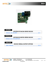
2.2 - CONNECTION
Before installing the option, verify that your instrument is compatible with output option MAN. The connection of analog
card will be printed on the label of related MICRA and looks like in fig 6.2. Remember that if the instrument is not carrying this
kind of label ,is not prepared to work with analog output MAN and should be damaged.
T
o perform wiring connections,remove the
terminal block from the meter’s
connector,strip the wire leaving from 7 to 10
mm exposed and insert it into the proper
terminal pushing the fingertip down to open
the clip inside the connector as indicated in
the fig 6.3.
Proceed in the same manner with all pins
and plug the terminal block into the
corresponding meter´s connector. Each
terminal can admit cables of section
between 0.08 mm² and 2.5 mm² (AWG 26
÷ 14).
WARNING:
In order to guarantee electromagnetic
compatibility, the following guidelines should
be kept in mind:
- Use shielded cable for signal wiring and
connect the shield to ground of the
indicator (pin2 CN1).
- The cable section must be
≥ 0.25 mm².
If not installed and used in accordance with
these instructions, protection against hazards
ma
y
be im
p
aired.
Fig 6.2. Description
of conection MAN
Fig 6.1. Rear view of the instrument
Fig 6.3. Wiring connections
MAN
2 1
MAN – ANALOG OUTPUT OPTION
PIN 2 = (- ) 4-20 mA
PIN 1 = (+) 4-20 mA
2.2 - CONNECTION
Before installing the option, verify that your instrument is compatible with output option MAN. The connection of analog
card will be printed on the label of related MICRA and looks like in fig 6.2. Remember that if the instrument is not carrying this
kind of label ,is not prepared to work with analog output MAN and should be damaged.
T
o perform wiring connections,remove the
terminal block from the meter’s
connector,strip the wire leaving from 7 to 10
mm exposed and insert it into the proper
terminal pushing the fingertip down to open
the clip inside the connector as indicated in
the fig 6.3.
Proceed in the same manner with all pins
and plug the terminal block into the
corresponding meter´s connector. Each
terminal can admit cables of section
between 0.08 mm² and 2.5 mm² (AWG 26
÷ 14).
WARNING:
In order to guarantee electromagnetic
compatibility, the following guidelines should
be kept in mind:
- Use shielded cable for signal wiring and
connect the shield to ground of the
indicator (pin2 CN1).
- The cable section must be
≥ 0.25 mm².
If not installed and used in accordance with
these instructions, protection against hazards
ma
y
be im
p
aired.
Fig 6.2. Description
of conection MAN
Fig 6.1. Rear view of the instrument
Fig 6.3. Wiring connections
MAN
2 1
MAN - OPCION SALIDA ANALOGICA
PIN 2 = (-) 4-20 mA
PIN 1 = (+) 4-20 mA

6
9
6
3. TECHNICAL SPECIFICATIONS
OUTPUT 4-20 mA
Resolution..............................................................................................................12 bits
Accuracy........................................................................... 0.2 % F.S ±1 bit at 23 º ±5 ºC
Response time.......................................................................................................120 ms
Thermal drift.......................................................................................................2 μA/ ºC
Maximum load........................................................................................................ 500 Ω
Isolation between analog output and input signal................................................3750 V AC
Isolation between analog output and power supply and relay output......................2300 V AC
3. TECHNICAL SPECIFICATIONS
OUTPUT 4-20 mA
Resolution..............................................................................................................12 bits
Accuracy........................................................................... 0.2 % F.S ±1 bit at 23 º ±5 ºC
Response time.......................................................................................................120 ms
Thermal drift.......................................................................................................2 μA/ ºC
Maximum load........................................................................................................ 500 Ω
Isolation between analog output and input signal............................................... 3750 V AC
Isolation between analog output and power supply and relay output..................... 2300 V AC

7
7
Apply power to the instrument,it automatically enters in a self-test routine activating
all segments of the display, then the instrument will start in (RUN) mode. From this
point, press key ENTER to enter into programming mode. Display will show Pro with
led F4 on (see fig 8.1).
To accede the the analog output programming module , press repeatedly the
key until F2 turns on (see fig 8.2).
Previous Considerations
Programming the analog output consist of introducing the low and high value of the
range of display to be covered . Then the output signal will provide a current between
4 mA and 20 mA linearly proportional to the range of the display defined in this way.
Normaly ,it is enough to fit low and high ends with the ends of the display range; be
in direct or inverted relationship. Nevertheless, it is possible to programm the whole
span of analog output to a defined part of the display range. In every case, note that ,
when the instrument shows Overrange with positive slope the output signal will be
20 mA and when shows Overrange with negative slope the output signal will be 4 mA,
independently of other consideration.
4. PROGRAMMING INSTRUCTIONS
TARE
MAX/MI
N
DATA
ENTE
R
RS232C RS485
MIN
TARE
PROG
SET 1 SET 2
MAX
F4
F2
F3
F1
Fig. 8.1. Programming mode, led F4 on.
TARE MAX/ MIN DATA
ENTE
R
RS232C RS485
MIN
TARE
PROG
SET 1 SET 2
MAX
F4
F2
F3
F1
Fig. 8.2. Programming module of
analog output , led F2 y F4 on.

8
8
T
his menu adjust the display values that give the output signal at two ends of the range, the low value (LOW) and high value
(HIGH). In this way, the analog output will follow the change of display in the range choosed, geting 4 mA on the low value (or
overrange with negative slope) and 20 mA on high value (or overrange with positive slope). The values you programm in this
menu will show the decimal point if you have before chosen it in the SCAL menu , as is indicated in your MICRA manual.
MENU F2 - PROGRAMMING ANALOG OUTPUT
Display shows during 1 second the flag LO to point out that now are programming the
value of display that corresponds to 4 mA.
ENTER Allows to program the display value that corresponds to output 4 mA.
[9.1] Indication flag LOW
Programming of the display value for 4 mA output, led F4 on.
Introduce the value of display equivalent to low value of output signal, that means,
4mA. The initial value is shown with the first digit blinking. Push repeatedly the key
to modify the value of the active digit. Push the key to shift to next
digit and repeat the same operation until getting on display the desired value. If we
wish to programm a negative value, at the end of numerical sequence of first digit
we can select the negative sign.
ENTER Stores this value into memory and goes to next step.
[9.2] Low Value
TARE MAX/ MIN DATA
ENTE
R
RS232C RS485
MIN
TARE
PROG
SET 1 SET 2
MAX
F4
F2
F3
F1
TARE MAX/ MIN DATA
ENTE
R
RS232C RS485
MIN
TARE
PROG
SET 1 SET 2
MAX
F4
F2
F3
F1

9
9
Programming of the display value for 20 mA output, led F4 on.
Insert the value of display equivalent to high value of output signal, that means, 20
mA. The initial value is shown with the first digit blinking. Push repeatedly the key
to modify the value of the active digit. Push the key to shift to next
digit and repeat the same operation until getting on display the desired value. If we
wish to program a negative value, at the end of numerical sequence of first digit we
can select the negative sign.
ENTER Stores this value into memory and goes to next figure.
[10.2] High value
TARE MAX/ MIN DATA
ENTE
R
RS232C RS485
MIN
TARE
PROG
SET 1 SET 2
MAX
F4
F2
F3
F1
Display shows during 1 second the flag HI to point out that now are programming the
value of display that corresponds to 20 mA.
ENTER Allows to program the display value that corresponds to output 20 mA.
[10.1] Indication flag HIGH
TARE MAX/ MIN DATA
ENTE
R
RS232C RS485
MIN
TARE
PROG
SET 1 SET 2
MAX
F4
F2
F3
F1
At this point,push key until having only F4 on, and then ENTER to go back to
run mode ,the analog output has been programmed.
[10.3] Return to run mode
TARE MAX/ MIN DATA
ENTE
R
RS232C RS485
MIN
TARE
PROG
SET 1 SET 2
MAX
F4
F2
F3
F1

10
10
The instruments are warranted against defective materials and workmanship for a period of
three years from date of delivery.
If a product appears to have a defect or fails during the normal use within the warranty
period, please contact the distributor from which you purchased the product.
This warranty does not apply to defects resulting from action of the buyer such as
mishandling or improper interfacing.
The liability under this warranty shall extend only to the repair of the instrument. No
responsibility is assumed by the manufacturer for any damage which may result from its
use.
All the DITEL products benefit from an unlimited and unconditional warranty of THREE (3)
years from the date of their purchase. Now you can extend this period of warranty up to
FIVE (5) years from the product commissioning, only by fulfilling a form.
Fill out the form in our website:
http://www.ditel.es/warranty


DISEÑOS Y TECNOLOGIA, S.A.
Polígono Industrial Les Guixeres
C/ Xarol 8 C
08915 BADALONA-SPAIN
Tel : +34 - 93 339 47 58
Fax : +34 - 93 490 31 45
E-mail : [email protected]
www.ditel.es
DISEÑOS Y TECNOLOGIA, S.A.
Polígono Industrial Les Guixeres
C/ Xarol 8 C
08915 BADALONA-SPAIN
Tel : +34 - 93 339 47 58
Fax : +34 - 93 490 31 45
E-mail : [email protected]
www.ditel.es
INSTRUCTIONS FOR THE RECYCLING
This electronic instrument is covered by the 2002/96/CE European Directive so, it is properly marked with
the crossed-out wheeled bin symbol that makes reference to the selective collection for electrical and
electronic equipment which indicates that at the end of its lifetime, the final user cannot dispose of it as
unsorted municipal waste.
In order to protect the environment and in agreement with the European legislation regarding waste of
electrical and electronic equipments from products put on the market after 13 August 2005, the user can
give it back, without any cost, to the place where it was acquired to proceed to its controlled treatment and
recycling.
/