Sony MPC-3610 Operating instructions
- Category
- Camcorders
- Type
- Operating instructions
This manual is also suitable for

© 2017 Sony Corporation
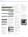
Digital Motion Picture Camera
VENICE
Operating Instructions
MPC-3610
Firmware Version 3.0
4-735-109-13 (1)
GB

0002
1. Overview
Features ..............................................................................3
System Configuration ........................................................6
Location and Function of Parts ..........................................7
2. Preparation
Preparing a Power Supply ...............................................15
Setting the Clock .............................................................. 16
Attaching the VF Attachment and Handle ......................17
Mounting a Lens and Adjusting the Flange
Focal Length ............................................................18
Attaching a Viewfinder .................................................... 21
Handling SxS Memory Cards ........................................... 23
Handling SD Cards for Saving Configuration Data .......... 25
Using with AXS-R7 ..........................................................26
3. Camera Operations
Sub Display .......................................................................28
Operations on the Home Screen of the Sub Display ....... 31
User Functions Screen ......................................................37
Menu Operations .............................................................40
Full Menu Operations.......................................................50
Full Menu List ...................................................................51
Clip Operations on the Sub Display .................................67
Playback ...........................................................................69
Operations on the Home Screen of the Mini Display ...... 70
Clip Operations on the Mini Display ................................ 72
4. Network
Network Setup and Operations .......................................73
5. Shooting
Basic Operations ...............................................................77
Useful Functions ...............................................................78
6. Connecting External Devices
Connecting External Monitors and Recording
Devices ..................................................................... 80
External Synchronization ................................................. 82
7. Appendix
Usage Precautions ............................................................83
Recording Formats and Output Signals ..........................86
Error/Warning Indications ............................................... 94
Items Saved in Files ..........................................................96
Licenses ..........................................................................102
Specifications .................................................................103
Table of Contents

0003
1. Overview
Features
New 36×24 mm Full Frame CMOS
Image Sensor
Supports image capture at resolutions up to 6048
× 4032 pixels.* By switching the imager mode, the
unit can natively support many shooting formats,
including Super 35 24.3 × 12.8 mm, 4096 × 2160
pixel resolution (equivalent to 3-perforation
motion picture film) and 4:3 Anamorphic* Super
35 24.3 × 18.3 mm, 4096 × 3024 pixel resolution
(equivalent to 4-perforation motion picture film).
* Full Frame and Anamorphic modes require licenses sold
separately.
Wide Latitude
The unit supports 15+ stops of latitude. It features
very low noise for delivering phenomenal images
in conditions from searing sunlight to almost
no light, allowing for unprecedented creative
freedom in grading.
Wide Color Space Capture
Images can be captured in a color space that
exceeds DCI-P3. The degree of freedom in the
grading is dramatically improved when using
Sony’s S-Gamut and S-Gamut3.Cine color space
together with S-Log3.
Dual Base ISO
The unit supports two selectable native ISO
settings (ISO500 and ISO2500). Using Base ISO500
under normal lighting conditions and Base
ISO2500 under low light conditions allows you
to maintain the latitude balance between bright
and low light conditions when shooting, without
graining (noise).
PL Lens Mount
Equipped with the industry-standard PL lens
mount. The lens mount supports Cooke /i
technology, and lens information is recorded as
metadata frame by frame.
E Mount Lens
E mount lenses are supported by removing the PL
lens adaptor. E mount lenses are smaller and lighter
than PL lenses, and are available in a diverse lineup for
expanded possibilities in image reproduction.
Compact Body and Intuitive
Operation
A relatively compact design for a device equipped
with a large Full Frame image sensor, achieved
using Sony’s miniaturization technology, which
allows easier shooting in confined spaces or on
drones.
The position, shape, and size of the control
buttons reflect the requirements of camera
operators for intuitive operation. They also feature
backlighting for ease of use in dark locations.
Engineered to Survive
The chassis is made from magnesium alloy for
high robustness and durability. The ventilation
system is completely isolated from all electronic
components to prevent ingress of dust, sand, and
liquids.*
The silent-running fan can be cleaned or even
swapped out on set quickly and easily to maintain
high redundancy.
* Design protects against dust and rain, but cannot
completely prevent the ingress of dust and liquid.
Modular Design
Features a fully modular design, allowing you
to flexibly support various rigs and peripheral
equipment according to the shooting application.
The top handle and viewfinder are easily adjustable
to maintain ergonomic balance and ease of use with
lenses. The height of the optical axis is the same
as the PMW-F55, permitting the use of peripheral
devices used with the PMW-F55. And an optional
AXS-R7 Portable Memory Recorder can be securely
attached to the rear of the unit using four hex
screws.
8-Position Optical ND Filter
Employs an 8-position optical ND filter. It offers
a wide ND range of 0.3ND (1/2 = 1 stop) to
2.4ND (1/256 = 8 stops) that reduces time lost
on set changing external ND filters. The ND filter
mechanism is servo-controllable.
Intuitive and Familiar On-Set
Operation
The menu screen is available from both sides of
the camera, with the main control display on the
Assistant side of the camera for fast access to the
camera settings by the camera assistant while
shooting.
An OLED mini display on the Operator side allows
the operator to access commonly accessed
features such as ND filter position, shutter, white
balance, exposure index (EI), and frame rate (FPS),
making it convenient for the operator to check the
status of the unit.
Various Recording Formats
The unit supports recording on SxS memory cards
in XAVC 4K/QFHD, MPEG HD, and HD ProRes 422
formats. In addition, it can record in 16-bit RAW or
X-OCN format onto AXS memory cards when used
in combination with an optional AXS-R7 Portable
Memory Recorder.
Imager Block Extension
The imager block can be extended from the
camera body by 2.7 m (8.9 ft) or 5.5 m (18 ft) by
connecting the CBK-3610XS* Camera Extension
System.
* Update the firmware to version 3.0 or later.

000
1. Overview: Features
4
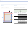
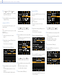
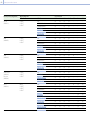
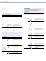
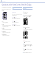
Effective Picture Size
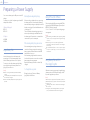
The unit supports shooting in the following effective picture sizes.
[Note]
A software license is required to shoot in 6K 17:9, 6K 1.85:1, 6K 2.39:1, 6K 3:2, 5.7K 16:9, 4K 4:3, and 4K 6:5.
6K 3:2
6K 1.85:1
6K 17:9
4K 6:5
4K 4:3
6K 2.39:1
4K 17:9
(DCI 4K)
3.8K 16:9
(Ultra HD)
5.7K 16:9
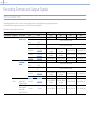
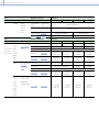
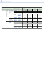
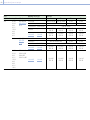
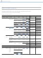
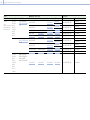
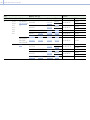
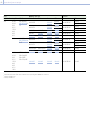
Software Licenses
You can select software licenses (optional) according to the intended usage of the unit.
Software licenses are installed using Maintenance > License Options (page 66) in the full menu.
Software license Imager mode Effective
number of
pixels
(Image pixels)
W × H (mm) Project frame rate
License not required* 3.8K 16:9 3840 × 2160 22.8 × 12.8 23, 24, 25, 29, 50, 59
3.8K 16:9
Surround View
3840 × 2160
(4268 × 2400)
22.8 × 12.8
(25.4 × 14.3)
23, 24, 25, 29
4K 17:9 4096 × 2160 24.3 × 12.8 23, 24, 25, 29, 47, 50, 59
4K 17:9
Surround View
4096 × 2160
(4552 × 2400)
24.3 × 12.8
(27.0 × 14.3)
23, 24, 25, 29
Anamorphic License 4K 4:3 4096 × 3024 24.3 × 18.0 23, 24, 25, 29, 47
4K 4:3 Surround
View
4096 × 3024
(4552 × 3360)
24.3 × 18.0
(27.0 × 20.0)
23, 24, 25, 29
4K 6:5 4096 × 3432 24.3 × 20.4 23, 24, 25, 29
Full Frame License* 5.7K 16:9 5670 × 3190 33.7 × 18.9 23, 24, 25, 29
6K 2.39:1 6048 × 2534 35.9 × 15.0 23, 24, 25, 29
6K 17:9 6054 × 3192 36.0 × 19.0 23, 24, 25, 29
6K 1.85:1 6054 × 3272 36.0 × 19.4 23, 24, 25, 29
6K 3:2 6048 × 4032 35.9 × 24.0 23, 24, 25
* The Anamorphic license is required to enable ratio settings, other than Off(1.0×), for the de-squeeze function.

000
1. Overview: Features
5
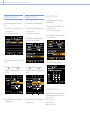
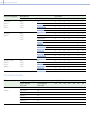
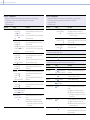
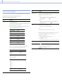
Surround View
Surround View is a mode available in the following imager modes that displays an image range that
includes a 5% outer region beyond the effective picture size (top/bottom/left/right) in the viewfinder and
SDI monitor output, allowing you to view a larger image range when shooting. The recorded image area
does not include the outer region.
3.8K 16:9
4K 17:9
4K 4:3
[Notes]
In this mode, limitations on the maximum project frame rate setting may apply.
In 4K 4:3 mode with de-squeeze ratio of 2.0×, the image area includes only 5% of the top and bottom outer regions.

000
1. Overview
6
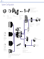
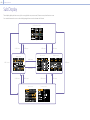
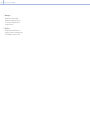
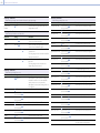
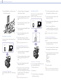
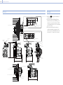
System Configuration
MPC-3610
VCT-FSA5
Shoulder Adaptor
DVF-L700
Viewfinder
(VF cable (A-2201-632-A or
A-2201-633-A) is required)
DVF-EL200
Viewfinder
ECM-680S, ECM-678,
ECM-674
Microphone
(EC-0.5X3F5M is
required)
Microphone Holder (A-2182-620-A)
Rod Clamp (A-2182-621-A)
Rod (4-684-612-01)
Microphone Holder assembly (X-2596-733-2)
Screws P2.6×8 (2) (7-627-556-98)
SBP-64/128/256E, SBS-32/64/128G1C
SxS Memory Card
QD-G32E/G64E/G120F/G240F
XQD Memory Card
(QDA-EX1 XQD ExpressCard Adaptor is required)
SBAC-US30/UT100
USB Card Reader
AC-DN2B, AC-DN10
AC Adaptor
AXS-AR1
AXS Memory Card Reader
BP-FL75, BP-FLX75
Battery Pack
SCL-PK6,
SCL-P11X15
S35 PL Lens
CBKZ-3610A,
CBKZ-3610AM,
CBKZ-3610AW
Anamorphic
License
CBKZ-3610F,
CBKZ-3610FM,
CBKZ-3610FW
Full Frame License
Anamorphic Lens
(PL mount / E mount)
CBK-3610XS
Camera Extension System
Full Frame Lens
(PL mount / E mount)
SELP28135G, SEL1635GM, SEL2470GM, SEL70200GM, SEL100400GM,
SEL1224G, SEL35F14Z, SEL50F14Z, SEL85F14GM, SEL90M28G,
SEL100F28GM
E Mount Lens
AXS-R7
Portable Memory
Recorder
AXS-A256S24, AXS-A512S48,
AXS-A512S24, AXS-A1TS48,
AXS-A1TS24
AXS Memory Card
AXS-AR1, AXS-CR1
AXS Memory Card
Reader

000
1. Overview
7
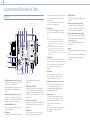
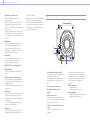
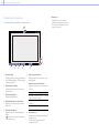
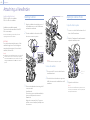
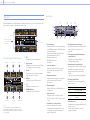
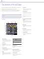
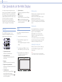
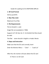
Location and Function of Parts
Operator Side
4
678910111213
15
16
14
1 2 3
5
Air inlet
SxS memory card
slot block (page 8)
1. ASSIGN (assignable) buttons 1/2 (page 37)
Assign functions using the EDIT page of the
user functions screen (page 37).
The assigned function toggles between on/off
(enable/disable) or is activated with each
press.
2. ASSIGN (assignable) lamps 1/2 (page 37)
Each lamp is lit orange when the assigned
function is on (enabled) or activated, and not
lit when the function is off (disabled).
3. Mini display ITEM keys 1 to 3
Controls the operation of functions on the
mini display (page 70).
4. Mini display
Displays various setup items, such as shutter
angle, that you can check or modify
(page 70).
5. ACCESS lamps (SLOT A/B)
Each lamp is lit when the recording media in
SxS card slot A/B is the target for recording/
playback and when data is being written to or
read from the recording media in SxS card slot
A/B (page 23).
6. Network connector (RJ-45)
Connect to a wired LAN network using a LAN
cable (not supplied) for remote control of the
unit (page 73).
7. CLIPS button
Press to display the clip screen on the mini
display to enable clip operations (page 72).
Simultaneously, the clip list screen is displayed
on the sub display and can also be used for
clip operations.
To switch from playback mode to shooting
mode, press the HOME button.
8. Power switch
Set to the ON position () to turn the power on.
Set to the OFF position () to turn the power
off.
[Notes]
This unit uses a small amount of standby power
even when the power switch is set to OFF. Remove
the battery pack if the unit will not be used for a
prolonged period.
When removing the battery pack or the DC IN
power, be sure to first set the power switch to the
OFF position. Interrupting the power supply during
recording or during memory card access could cause
a malfunction.
9. HOME button
Press to clear the item selection display and
return to the Home screen on the mini display.
If pressed when the unit is in playback state,
the unit transitions to shooting mode
(page 70).
10. LOCK switch
Locks the operation of the buttons on the
Operator side. When locked, the switch
background LED lights in orange.
11. Headphones connector (stereo mini jack)
Connect to earphones for audio monitoring.
You can monitor the input audio during
shooting/recording and playback sound
during playback (page 69).
12. Built-in speaker
You can monitor the input audio during
shooting/recording and playback sound
during playback. The speaker also sounds
alarms to reinforce visual warnings
(page 69).
If you connect earphones to the headphones
jack, the speaker output is suppressed
automatically.
13. REC ACTIVE lamp
The lamp is lit green when the REC button is
enabled.
14. ASSIGN (assignable) lamp 3 (page 37)
The lamp is lit orange when the assigned
function is on (enabled) or activated, and not
lit when the function is off (disabled).
15. REC (recording start/stop) button/lamp
Press to start recording, turning the REC lamp
on. Press again to stop recording, turning the
REC lamp off (page 77).
The REC lamp flashes when a device error or
warning occurs.
16. mark
The mark is on the same plane as the image
sensor.
To measure the precise distance between the
unit and the subject, use the mark as a
reference.

000
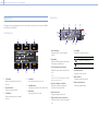
1. Overview: Location and Function of Parts
8
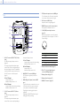
SxS memory card slot block (page 23)
The SxS memory card slots are located behind the
cover.
1
3
2
1. SxS memory card slots A/B
2. Manufacturer calibration terminal
Manufacturer terminal for calibration and
servicing (cannot be used by users).
3. SLOT SELECT (SxS memory card select)
button
Press to switch the active slot.
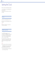
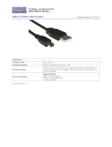
Assistant Side
1 2 3 4
6
5
7
8
9
1011
12
13
14
15
16
17
18
1 2 3
4 5 6
1. ASSIGN (assignable) button 4 (page 37)
Assign functions using the EDIT page of the
user functions screen (page 37).
The assigned function toggles between on/off
(enable/disable) or is activated with each
press.
2. ASSIGN (assignable) lamp 4 (page 37)
The lamp is lit orange when the assigned
function is on (enabled) or activated, and not
lit when the function is off (disabled).
3. Sub display
Allows you to check the operation status of
the unit and make various settings
(page 29).
With the Home screen displayed, press and
hold the BACK button (page 9) and turn
the SEL/SET dial to adjust the brightness of the
sub display and mini display.
The brightness can also be adjusted using
Technical > Control Display > Brightness level
(page 64) in the full menu.
4. Sub display ITEM keys 1 to 6
Controls the operation of functions on the sub
display (page 40).
5. Tape measure hook
The tape measure hook is on the same plane
as the image sensor. To measure the precise
distance between the unit and the subject, use
the tape measure hook as a reference. You can
attach the end of a tape measure to the hook,
and measure the distance from the subject.
6. HOME button
Press to clear the display and return to the
Home screen on the sub display (page 31).
If pressed when the unit is in playback state,
the unit transitions to shooting mode.
7. MENU (menu display on/off) button (pages
40, 50)
Press the MENU button to display the menu
screen on the sub display. Press and hold the
MENU button for 2 seconds or longer to
display the full menu screen on the sub
display. Press the button during menu screen
or full menu screen display to return to the
previous screen display.
8. SEL/SET (select/set) dial (MENU dial)
Changes the item selection or a setting within
the menu (pages
31
,
40
,
50
).
9. +48V power lamp
Lights in green if the AUDIO IN switch is set to
MIC and +48 V phantom power is supplied on
the AUDIO IN connector. It is not lit if phantom
power is not supplied.
You can turn +48 V phantom power on/off
using Audio category > Audio Details > Audio
Configuration > Phantom Power +48V
(page 62) in the menu.
10.
AUDIO IN (audio selector) switch
Select the input signal type corresponding to
the audio source connected to the AUDIO IN
connector.
LINE: When connecting an external analog
audio signal source
AES/EBU: When connecting an external digital
audio signal source
MIC: When connecting a microphone

000
1. Overview: Location and Function of Parts
9
11. AUDIO IN connector (XLR 5-pin)
Input external microphone or audio
equipment signals.
When the audio source is set to LINE or MIC
using the AUDIO IN switch, this connector
functions as an AUDIO IN CH-1 and AUDIO IN
CH-2 connector.
When the audio source is set to AES/EBU using
the AUDIO IN switch, this connector functions
as an AUDIO IN CH-1/2 and AUDIO IN CH-3/4
connector.
12. BACK button
Cancels the menu setting and moves up one
level in the menu hierarchy during menu
display.
Cancels the execution process or
pending process during process execution/
pending display (pages 31, 40, 50).
13. LOCK switch
Locks the operation of the buttons on the
Assistant side. When locked, the switch
background LED lights in orange.
14. ACCESS (SD card access) lamp (page 25)
15. REC ACTIVE lamp
The lamp is lit green when the REC button is
enabled.
16. REC (recording start/stop) button/lamp
Press to start recording, turning the REC lamp
on. Press again to stop recording, turning the
REC lamp off (page 77).
The REC lamp flashes when a device error or
warning occurs.
17. CLIPS button
Press to display the clip list screen on the sub
display to enable clip operations (page 67).
Simultaneously, the clip screen is displayed on
the mini display.
To switch from playback mode to shooting
mode, press the HOME button.
18. USER button
Press to display the user function list on the
sub display, and to operate the ITEM keys 1 to
5 user function buttons.
ITEM key 6 is the user function list EDIT button.
Press this button to display the function
selection screen for the user function buttons
and assignable buttons. Press again when the
user functions screen is displayed to return to
the previous display (page 37).
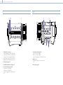
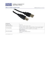
Front
1
23
4
5
1. ASSIGN (assignable) button 3 (page 37)
Assign functions using the EDIT page of the
user functions screen (page 37).
The assigned function toggles between on/off
(enable/disable) or is activated with each
press.
2. PL lens mount adaptor (page 18)
3. VF (viewfinder output) connector
(page 21)
4. LENS connector (12-pin)
Used only for iris control from a network-
connected computer, smartphone, or tablet in
firmware version 3.0 or later.
5. 24V OUT connector (DC OUT 24 V, Fischer
3-pin)
24 V DC power supply output connector
(page 80).
The output voltage and maximum output
current of this connector vary depending on
the input voltage to the unit. The maximum
current includes the output current from the
24V OUT connector on the rear panel
(page 10).
11 V to 17 V input
Output voltage : 24 V
Maximum output current: 1.0 A
22 V to 32 V input
Output voltage: Same as the input voltage
Maximum output current: 2.0 A

000
1. Overview: Location and Function of Parts
10
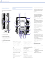
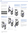
Rear
2
1
3
4
5
6
7
8
9
10
11
12
13
1. 24V OUT connector (DC OUT 24 V, Fischer
3-pin)
24 V DC power supply output connector
(page 80).
The output voltage and maximum output
current of this connector vary depending on
the input voltage to the unit. The maximum
current includes the output current from the
24V OUT connector on the front panel
(page 9).
11 V to 17 V input
Output voltage : 24 V
Maximum output current: 1.0 A
22 V to 32 V input
Output voltage: Same as the input voltage
Maximum output current: 2.0 A
2.
12V OUT connector (DC OUT 12V, Hirose
4-pin)
12 V DC power supply output connector
(page 80).
The output voltage and maximum output
current of this connector vary depending on
the input voltage to the unit.
11 V to 17 V input
Output voltage: Same as the input voltage
Maximum output current: 1.0 A
22 V to 32 V input
Output voltage : 15 V
Maximum output current: 0.8 A
3. MONITOR OUT connector (BNC type)
HD SDI monitor signal output connector
(page 80).
4. GENLOCK (genlock input) connector (BNC
type)
To genlock the unit to an external source or to
lock the timecode of the unit to an external
source, input an external reference signal.
Digital signal and analog signal input are
supported.
Digital signal: 1.5G HDSDI interlaced signal
Analog signal: HD sync, Analog
5. TC IN (timecode input) connector (BNC type)
To lock the timecode of the unit to an external
source, input a reference timecode signal.
6. AUX connector (LEMO 5-pin)
Outputs the timecode signal (page 81).
7. REMOTE (remote control) connector (8-pin)
Not supported in firmware version 3.0.
8. 12V/24V (DC power input) connector
(page 15)
DC power supply input connector for external
power supply to the unit. Supports 12 V and 24
V input voltages.
No. Signal
1 GND
2 NC
3 NC
4 DC IN (11 V to 17 V or 22 V to 32 V)
9. Battery attachment terminal (page 15)
10. SDI OUT 1 to 4 (serial digital output)
connectors (BNC type) (page 80)
11. Battery pack mount (page 15)
12. Battery release lever (page 15)
13. HDMI OUT connector (page 80)

000
1. Overview: Location and Function of Parts
11
Top
1 2 3 4
1. External device connector
Used for updating an AXS-R7 AXS Recorder
(option) when the AXS-R7 is attached to the
unit (page 27) or for using camera wireless
remote control (page 73) by connecting a
CBK-WA02 Wireless LAN Adaptor (option).
2. Release button (page 17)
3. Handle/VF attachment mount (page 17)
4. Accessory mounting screw holes
Type of screw: 1/4-20UNC (8)
Type of screw: 3/8-16UNC (10)
Length of engagement: 10 mm (3/8 inch) or
less
Bottom
3
1 2
Air vent
1. Tripod plate attachment holes
Type of screw: 1/4-20UNC (2)
Type of screw: 3/8-16UNC (4)
Length of engagement: 9 mm (3/8 inch) or less
2. Bottom cover
Remove the four hex screws to remove the
cover.
3. SD card slot (page 25)

000
1. Overview: Location and Function of Parts
12
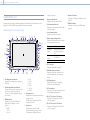
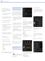
Viewfinder/Monitor Screen
During shooting (recording or standby) and playback, the information selected in Monitoring > OSD
Appearance > Status Info A/B Setup (page 58) in the full menu is displayed.
Information displayed on the screen while recording
27
1 2 3 64 5 7 9
212223242526
10
8
11
14
15
16
17
18
19
20
12
13
31
33
34
32
28
29
30
35
1. Recording frame rate indicator
Displays the recording frame rate and project
frame rate.
2. Shutter angle/shutter speed indicator
Displays the shutter angle or shutter speed of
the electronic shutter, according to the
Technical > System Configuration setting in
the full menu.
3. ND filter indicator
Displays the density of the ND filter. The
display value is a LOG (base 10) value
(page 51).
CLEAR
0.3 (1/2)
0.6 (1/4)
0.9 (1/8)
1.2 (1/16)
1.5 (1/32)
1.8 (1/64)
2.1 (1/128)
2.4 (1/256)
4. Thermometer icon
Displayed when a high temperature warning
message is issued.
The description is displayed in the Info
category in the menu.
5. Warning icon
Displayed when other than a high
temperature warning message is issued.
The description is displayed in the Info
category in the menu.
6. Exposure index indicator
Displays the exposure index (EI) value.
7. Color temperature indicator
Displays the color temperature and Tint value
of the white balance.
8. Look information display
Displays the selected Look (page 52).
9. Battery capacity/voltage indicator
Displays the following indicators according to
the type of battery power source.
Battery type Display
InfoLithium
battery
Battery remaining capacity
and remaining recording
time
Anton/Bauer
battery
Remaining battery capacity
(% indicator)
Other batteries
Input voltage
10. VF LUT indicator
Displays the viewfinder LUT (page 52).
11. VF Double Speed Scan indicator
Displays the on/off state of the function for
doubling the frame rate of the viewfinder
display.
12. VF Peaking indicator
Displays the on/off state of the peaking
function of the viewfinder display.
13. VF Zebra indicator
Displays the on/off state of the zebra function
of the viewfinder display (page 39).
14. SDI OUT 1/2 connector LUT indicator
Displays the LUT setting of the SDI OUT 1/2
connectors (page 52).
15. SDI OUT 3/4 connector LUT indicator
Displays the LUT setting of the SDI OUT 3/4
connectors (page 52).
16. Monitor LUT indicator
Displays the LUT setting of the Monitor output
(page 52).
17. HDMI LUT indicator
Displays the LUT setting of the HDMI output
(page 52).

000
1. Overview: Location and Function of Parts
13
18. SDI output REC trigger indicator
Displays the SDI output REC trigger status.
State Display
Technical > System Configuration > SDI Rec Remote
Trigger in the full menu
Recording command
superimposed on the
SDI output
Off – (Blank)
HD SDI Remote I/F Stop command Top: SDI
Bottom: Stop
Rec command Top: SDI
Bottom: REC
Parallel Rec Stop command Top: SDI-P
Bottom: Stop
Rec command Top: SDI-P
Bottom: REC
19. Network connection status indicator
Displays the network connection status (LAN
or Wi-Fi).
State Display
Disconnected or other error (valid
network connection settings)
Flashing
Connected (valid network connection
settings)
On
Network connection function not
used
Blank
20. Audio level meter indicators
Displays the levels of audio channels 1 and 2
while recording.
21. Recording media state/remaining capacity
indicator for each media slot
Displays the state and remaining capacity of
the media in SxS memory card slots A/B and
AXS memory card slots A/B.
A
mark on the left of “AXS” or “SxS” indicates
the recording target media.
An indicator
on the upper right of the slot
A/B icon on the right of “AXS” or “SxS” indicates
the playback target media (green indicator
indicates media is being played).
A
icon is displayed for media if a condition
occurs that could impact recording.
22. High Key/Low Key indicator (Monitor output)
Displayed when the Monitor output is High
Key (screen for checking blown-out highlights)
or Low Key (screen for checking blocked-out
shadows) (displayed for Monitor Out output).
23.
Recording media format (codec) indicator
Displays the format of the recording on an AXS
memory card or an SxS memory card .
24. Recording status indicator
Displays the following recording operation
states of the unit.
Display Description
Rec
Recording
Stby
Recording standby
Cache
Picture cache recording
standby
25. Clip name display
Displays the first 8 characters of the name of
the next clip to be recorded in recording
standby mode.
Displays the first 8 characters of the name of
the clip currently being recorded when
recording.
26. Time data display
Displays the duration or timecode, depending
on the TC/Media category > TC Display setting
in the menu (page 41).
27. Iris position indicator
Displays the iris position (only when a lens that
is compatible with the iris setting display
function is attached). The iris position indicator
displays in 1/3 stop increments when using an
E mount lens.
[Note]
The F-stop value is displayed instead of the T-stop value
if the T-stop value cannot be obtained.
28. Focus position indicator
Displays the focus position (only when a lens
that is compatible with the focus setting
display function is attached).
29. Zoom position indicator
Displays the focal length of the zoom
(displayed only when a lens that supports the
zoom setting indicator is attached).
30. High Key/Low Key indicator (viewfinder
output)
Displayed when the viewfinder output is High
Key (screen for checking blown-out highlights)
or Low Key (screen for checking blocked-out
shadows) (displayed for viewfinder output).
31. Simultaneous recording status indicator
Displays the sub clip recording format in 1-slot
simultaneous recording mode (page 78).
32. SxS Sub LUT indicator
Displays the LUT setting to register for a sub
clip in SxS 1-slot simultaneous recording
mode.
33. SxS LUT indicator
Displays the LUT setting for SxS recording.
34. Base ISO indicator
Displays the configured native sensitivity.
35. Effective picture size indicator
Displays the effective picture size and whether
anamorphic de-squeeze conversion is applied,
set using Project category > Imager Mode in
the menu. In Surround View mode, a “Sur.V”
icon is displayed below the anamorphic
conversion factor icon (page 41).
Menu display and settings on the viewfinder
screen
When a DVF-EL200 is attached to the unit, press
and hold the Menu button on the DVF-EL200 to
display the Monitoring > VF Display (page 61)
and VF Function (page 61) setup menus on the
viewfinder screen. This allows you to configure
these functions while viewing the viewfinder
screen.

000
1. Overview: Location and Function of Parts
14
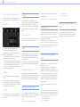
Information displayed on the playback screen
The following information is displayed on the playback picture.
98
54321
6
7
1. Time data display
Displays the duration or timecode, depending
on the TC/Media category > TC Display setting
in the menu (page 41).
2. Playback clip name display
Displays the first 8 characters of the name of
the playback clip.
3. Playback status indicator
Displays the playback status.
4. Playback media format (codec) indicator
Displays the recording format (codec) of the
playback clip.
5. Playback media indicator
Displays the type of recording media being
played.
A
icon appears on the right if the memory
card is write-protected.
6. Audio level meter indicators
Displays the levels of audio channels 1 and 2
during playback.
7. Network connection status indicator
Displays the network connection status (LAN
or Wi-Fi).
State Display
Disconnected or other error (valid
network connection settings)
Flashing
Connected (valid network connection
settings)
On
Network connection function not
used
Blank
8. Thermometer icon
Displayed when a high temperature warning
message is issued.
The description is displayed in the Info
category in the menu.
9. Warning icon
Displayed when other than a high
temperature warning message is issued.
The description is displayed in the Info
category in the menu.

00015
2. Preparation
Preparing a Power Supply
You can use a battery pack or AC power via an AC
adaptor.
For safety, use only the Sony battery packs and AC
adaptors listed below.
Lithium-ion battery pack
BP-FL75
BP-FLX75
AC adaptor
AC-DN2B
AC-DN10
Using a Battery Pack
Insert the battery pack into the battery pack
mount (page 10) of the battery adaptor, then
slide the battery pack down to lock it in place.
To remove it, unlock the battery pack by sliding
it up while pressing the battery release lever
(page 10), then remove it.
[Notes]
Before use, charge the battery pack with the battery
charger.
A warm battery pack immediately after use may not be
able to be fully recharged.
Remove the battery adaptor while supporting the unit
by hand.
Checking the remaining battery charge
When recording or playback is in progress using
the battery pack, the current battery remaining
time and battery voltage are displayed on the sub
display screen (page 29) and viewfinder/monitor
screen (page 12).
The unit indicates the remaining usage time in
minutes by calculating the available time with
the battery pack if operation is continued at the
current rate of power consumption.
If the remaining battery charge becomes low
If the remaining battery charge decreases to a
certain level during operation, the remaining
battery capacity indicator flashes and the REC
lamp flashes to warn you.
If the remaining charge further decreases to a
level at which operation cannot be continued, a
battery-empty message appears.
Replace the battery pack with one that is fully
charged.
To change the message levels
Change levels using Technical > Battery
(page 64) in the full menu.
Using AC Power (DC IN Power)
The unit works with AC power using the AC-DN10
(optional) or AC-DN2B AC adaptor (optional) and
CCDD-X2 DC cable (optional).
11 V to 17 V and 22 V to 32 V input voltage ranges
are supported.
[Notes]
When switching to the DC IN power supply during battery
operation, use a power supply with a voltage in the range
12V to 17 V.
When using a 22 V to 32 V power supply, first set the
power switch to the OFF position before connecting the
power supply.
Do not switch directly from a 11 V to 17 V power supply to
a 22 V to 32 V power supply, or vice versa. This may cause
a malfunction.
Using a Battery Pack and DC IN
Power Supply Together
Whenever an active power supply is applied using
a battery pack and a DC IN power supply, the DC
IN power supply takes precedence.
[Note]
When the power supply switches from battery operation to
the DC IN power supply, operation of the unit may stop if the
following occurs.
Chattering of the connector contacts when inserting the
DC connector
Voltage drop when switching between power supplies
(more prevalent when the external load is greater)

000
2. Preparation
16
Setting the Clock
When you use the unit for the first time, the initial
setup screen appears on the sub display when the
power is turned on.
Set the date and time of the built-in clock using
this display.
Time Zone
The value shows the time difference from UTC
(Coordinated Universal Time). Change the setting
if needed.
[Note]
When Time Zone is changed, the clock setting changes
according to the time difference.
Setting the Date and Time
Turn the MENU dial (page 8) to move the
cursor, then press the MENU dial to set each menu
item. When you press the MENU dial when the
cursor is on “Set,” the setting display disappears
and the clock setting is completed.
After the initial setup screen disappears, you can
change Time Zone and date/time settings using
Maintenance > Clock Set (page 65) in the full
menu.
[Notes]
If the clock setting is cleared because the backup battery
fully discharged when no power was supplied (no battery
pack and no DC IN connection), the initial setup display
will be displayed when you next turn the unit on.
While the initial setup display is shown, no other
operation, except turning the power off, is permitted until
you finish the setting for this display.

000
2. Preparation
17
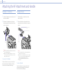
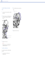
Attaching the VF Attachment
1 Slide the VF attachment on in the direction of
the arrow to attach it.
2 Position the VF attachment in the desired
front/rear position, then turn the lock lever to
secure it in position.
1
2
Lock
lever
[Notes]
You can also attach the VF attachment in the front/
rear or left/right orientation.
If the lock lever is difficult to tighten or loosen, you
can use a hex wrench (3mm) on the lock screw on
the top of the lock lever.
To remove the VF attachment
Turn the lock lever to loosen, press the release
button and slide the VF attachment off in the
reverse direction from when attaching it.
Attaching the Handle
1 Slide the handle on in the direction of the
arrow to attach it.
2 Position the handle in the desired front/rear
position, then turn the lock lever to secure it in
position.
2
1
Lock screw
Hex socket
bolt
Lock
lever
[Notes]
You can also attach a lock screw using a hex wrench
(5 mm) to secure it in position.
If the lock lever on the handle becomes loose during
use, you can secure the handle by tightening a hex
socket bolt (2 mm) beside the lock screw.
You can also attach the handle in the reverse
orientation.
To remove the handle
Turn the lock lever to loosen, press the release
button and slide the handle off in the reverse
direction from when attaching it.
Attaching the VF Attachment and Handle

000
2. Preparation
18
Recommended PL mount lens (Super 35mm size)
SCL-PK6/F, SCL-PK6/M (set of 6 lenses,
20mm/25mm/35 mm/50 mm/85 mm/135 mm)
SCL-PK3/F, SCL-PK3/M (set of 3 lenses,
20mm/25mm/135 mm)
SCL-P11X15
Recommended E mount lens
SELP28135G, SEL1635GM, SEL2470GM,
SEL70200GM, SEL100400GM, SEL1224G,
SEL35F14Z, SEL50F14Z, SEL85F14GM, SEL90M28G,
SEL100F28GM
[Note]
Control may not be supported with some E mount lenses.
Use a recommended lens.
For details about available lenses for the unit, contact a Sony
service representative.
[CAUTION]
Do not leave the lens facing the sun. Direct
sunlight can enter through the lens, be focused in
the unit, and cause fire.
[Notes]
Turn the unit off before attaching or removing the lens
and adapter.
A lens is a precision part. Do not place the lens down with
the mount side facing down. Attach the cap supplied
with the lens.
The lens interface of the unit is configured by factory
default for an SCL-P11X15 and lenses with Cooke type
connector. To use an SCL-PK6, SCL-PK3, or other lenses
that do not have a Cooke type connector, set Technical
> System Configuration > Lens Interface (page 62)
to Off in the full menu. If this setting is not correct, an
alert message appears when the unit is turned on after
attaching the lens.
Attaching a PL Mount Lens
1 Remove the mount cover from the lens mount
by turning the PL mount lever
counterclockwise.
PL mount
lever
[Note]
Turn the PL mount lever counterclockwise to the
stopper position.
2 Insert the lens into the lens mount by aligning
the concave part of the lens with the
positioning pin on the upper right of the lens
mount.
3 Secure the lens by turning the PL mount lever
clockwise while holding the lens.
[Note]
Do not turn the lens when attaching the PL mount lens.
It may cause damage to the hot shoe pin.
To attach a Cooke /i lens
Align the contacts on the lens with the hot shoe of
the unit. There are two connectors on the side of
the lens adaptor, and either can be used.
To remove the lens
1 Turn the PL mount lever counterclockwise
while holding the lens from underneath.
2 Pull the lens forward.
[Note]
If another lens will not be attached soon, carefully align
the concave part of the mount cover, then secure the
mount cover by turning the PL mount lever clockwise.
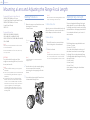
Adjusting the Flange Focal Length
The unit is shipped with the flange focal length
already adjusted. If you need to adjust the flange
focal length, remove the lens mount, and change
the shims with those of the appropriate thickness.
You can adjust the thickness by ±0.1 mm in 0.01
mm increments.
Shims
The following shims are supplied with the unit.
0.05 mm × 1 (circular)
0.01 mm × 15 (1/3 arc)
1/3 arc shims should always be used as a set of
three shims. Insert shims to increase the flange
focal length. The unit is shipped with the flange
focal length already adjusted using the following
three types of shims.
0.10 mm (circular)
0.05 mm (circular)
0.01 mm (1/3 arc)
A seal is attached showing the shim thickness
when shipped.
Mounting a Lens and Adjusting the Flange Focal Length

000
2. Preparation: Mounting a Lens and Adjusting the Flange Focal Length
19
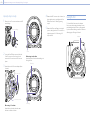
Adjusting the flange focal length
1 Remove the six Torx screws and remove the PL
mount flange.
1
PL mount flange
2 Loosen the four Phillips screws on both sides
of the PL connectors (two locations), and
remove the PL connectors and PL connector
plates.
3 Attach shims to the PL mount adaptor (three
locations).
33
3
3
3
3
2
2
2
2
PL connectors
PL connector plates
When using 1/3 arc shims
Attach shims so that they have the same
thickness in all three locations.
Shims
When using circular shims
Attach with the surface that has markings on it
facing the front.
Markings
Markings
4 Reattach the PC connectors (two locations) to
their original positions, and tighten the four
Phillips screws with 0.18 N·m tightening
torque.
5 Reattach the PL mount flange in its original
position, and tighten the six Torx screws to a
tightening torque of 0.35 N·m using a T8
torque wrench.
Cleaning the Filter
To clean the filter, first remove the adaptor.
Exercise care when wiping the adaptor center
part (shaded part) with a cloth or other material
to prevent fibers adhering to surfaces. If fibers are
adhering, wipe off using a soft brush.
Adaptor

000
2. Preparation: Mounting a Lens and Adjusting the Flange Focal Length
20
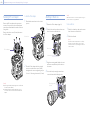
Removing the PL Lens Adaptor
Remove the PL lens adaptor when you want to
mount an E mount lens to the unit. Attachment/
removal is performed with the rear side of the unit
facing down.
Remove the six hex screws (2.5mm) and remove
the PL lens adaptor.
PL lens adaptor
[Notes]
Removing the battery and placing the rear side of the unit
face down provides stability.
When attaching/removing the adaptor, take care not
to touch the connector contacts of the unit and PL lens
adaptor.
To attach the PL lens adaptor
1 Check that the mount lever is in the locked
position.
Mount lever
2 Place the PL lens adaptor back in its original
position, insert the six hex screws (2.5mm),
and tighten the screws to a tightening torque
of 0.8 ± 0.12 N·m using a hex wrench (2.5mm).
Attaching an E Mount Lens
1 Remove the PL lens adaptor (page 20).
2 Push the lock switch up, and turn the mount
lever clockwise to release the lock.
Mount lever
Lock switch
3 Align the mounting marks (white) on the unit
and lens mount, and then push the lens into
the mount.
4 Secure the lens by turning the mount lever
counterclockwise while holding the lens.
Mounting marks
(white)
[Note]
When an E mount lens is connected, operation using a 12-
pin lens connector is not guaranteed.
To remove the lens
1 Push the lock switch up, and turn the mount
lever clockwise to release the lock.
2 Pull the lens forward.
[Note]
If another lens will not be attached soon, carefully
align the concave part of the mount cover, then
secure the mount cover by turning the mount lever
counterclockwise.
Page is loading ...
Page is loading ...
Page is loading ...
Page is loading ...
Page is loading ...
Page is loading ...
Page is loading ...
Page is loading ...
Page is loading ...
Page is loading ...
Page is loading ...
Page is loading ...
Page is loading ...
Page is loading ...
Page is loading ...
Page is loading ...
Page is loading ...
Page is loading ...
Page is loading ...
Page is loading ...
Page is loading ...
Page is loading ...
Page is loading ...
Page is loading ...
Page is loading ...
Page is loading ...
Page is loading ...
Page is loading ...
Page is loading ...
Page is loading ...
Page is loading ...
Page is loading ...
Page is loading ...
Page is loading ...
Page is loading ...
Page is loading ...
Page is loading ...
Page is loading ...
Page is loading ...
Page is loading ...
Page is loading ...
Page is loading ...
Page is loading ...
Page is loading ...
Page is loading ...
Page is loading ...
Page is loading ...
Page is loading ...
Page is loading ...
Page is loading ...
Page is loading ...
Page is loading ...
Page is loading ...
Page is loading ...
Page is loading ...
Page is loading ...
Page is loading ...
Page is loading ...
Page is loading ...
Page is loading ...
Page is loading ...
Page is loading ...
Page is loading ...
Page is loading ...
Page is loading ...
Page is loading ...
Page is loading ...
Page is loading ...
Page is loading ...
Page is loading ...
Page is loading ...
Page is loading ...
Page is loading ...
Page is loading ...
Page is loading ...
Page is loading ...
Page is loading ...
Page is loading ...
Page is loading ...
Page is loading ...
Page is loading ...
Page is loading ...
Page is loading ...
Page is loading ...
Page is loading ...
-
 1
1
-
 2
2
-
 3
3
-
 4
4
-
 5
5
-
 6
6
-
 7
7
-
 8
8
-
 9
9
-
 10
10
-
 11
11
-
 12
12
-
 13
13
-
 14
14
-
 15
15
-
 16
16
-
 17
17
-
 18
18
-
 19
19
-
 20
20
-
 21
21
-
 22
22
-
 23
23
-
 24
24
-
 25
25
-
 26
26
-
 27
27
-
 28
28
-
 29
29
-
 30
30
-
 31
31
-
 32
32
-
 33
33
-
 34
34
-
 35
35
-
 36
36
-
 37
37
-
 38
38
-
 39
39
-
 40
40
-
 41
41
-
 42
42
-
 43
43
-
 44
44
-
 45
45
-
 46
46
-
 47
47
-
 48
48
-
 49
49
-
 50
50
-
 51
51
-
 52
52
-
 53
53
-
 54
54
-
 55
55
-
 56
56
-
 57
57
-
 58
58
-
 59
59
-
 60
60
-
 61
61
-
 62
62
-
 63
63
-
 64
64
-
 65
65
-
 66
66
-
 67
67
-
 68
68
-
 69
69
-
 70
70
-
 71
71
-
 72
72
-
 73
73
-
 74
74
-
 75
75
-
 76
76
-
 77
77
-
 78
78
-
 79
79
-
 80
80
-
 81
81
-
 82
82
-
 83
83
-
 84
84
-
 85
85
-
 86
86
-
 87
87
-
 88
88
-
 89
89
-
 90
90
-
 91
91
-
 92
92
-
 93
93
-
 94
94
-
 95
95
-
 96
96
-
 97
97
-
 98
98
-
 99
99
-
 100
100
-
 101
101
-
 102
102
-
 103
103
-
 104
104
-
 105
105


Sony MPC-3610 Operating instructions
- Category
- Camcorders
- Type
- Operating instructions
- This manual is also suitable for
Ask a question and I''ll find the answer in the document
Finding information in a document is now easier with AI
Related papers
Other documents
-
 ANDYCINE 1 User guide
-
AJA Ki Pro Mini Quick start guide
-
Canon DP-V2420 User manual
-
 Cables Direct CDL-062-1.0 Datasheet
-
 Cables Direct CDL-103 Datasheet
-
 Cables Direct CDL-012 Datasheet
-
Feelworld 2200 nits User manual
-
Feelworld 6 Inches User manual
-
Canon DP-V2410 User manual
-
TVLogic LUM-240G Operating instructions


