Page is loading ...

Instruction Manual IM02602008E - Rev. D
Transformer Temperature Controllers

ii
Instruction Manual IM02602008E - Rev. D
Transformer Temperature Controllers IM02602008E - Rev. D May 2019 www.eaton.com
Copyright © 2019 by Eaton Corporation. All rights reserved.
Eaton, PowerChain Management, and TC-100 are registered trademarks of Eaton
Corporation or its subsidiaries and affiliates. Microsoft and Windows are registered
trademarks of Microsoft Corporation. Modbus is a registered trademark of Sch-
neider Electric.
EATON CORPORATION - CONFIDENTIAL AND PROPRIETARY NOTICE TO PER-
SONS RECEIVING THIS DOCUMENT AND/OR TECHNICAL INFORMATION
THIS DOCUMENT, INCLUDING THE DRAWING AND INFORMATION CONTAINED
THEREON, IS CONFIDENTIAL AND IS THE EXCLUSIVE PROPERTY OF EATON
CORPORATION, AND IS MERELY ON LOAN AND SUBJECT TO RECALL BY
EATON AT ANY TIME. BY TAKING POSSESSION OF THIS DOCUMENT, THE
RECIPIENT ACKNOWLEDGES AND AGREES THAT THIS DOCUMENT CANNOT
BE USED IN ANY MANNER ADVERSE TO THE INTERESTS OF EATON, AND THAT
NO PORTION OF THIS DOCUMENT MAY BE COPIED OR OTHERWISE REPRO-
DUCED WITHOUT THE PRIOR WRITTEN CONSENT OF EATON. IN THE CASE OF
CONFLICTING CONTRACTUAL PROVISIONS, THIS NOTICE SHALL GOVERN THE
STATUS OF THIS DOCUMENT.
DISCLAIMER OF WARRANTIES AND LIMITATION OF LIABILITY
The information, recommendations, descriptions and safety notations in this docu-
ment are based on Eaton Electrical Inc. and/or Eaton Corporation’s (“Eaton”) experi-
ence and judgment and may not cover all contingencies. If further information is
required, an Eaton sales office should be consulted.
Sale of the product shown in this literature is subject to the terms and conditions
outlined in appropriate Eaton selling policies or other contractual agreement be-
tween Eaton and the purchaser.
THERE ARE NO UNDERSTANDINGS, AGREEMENTS, WARRANTIES, EXPRESSED
OR IMPLIED, INCLUDING WARRANTIES OF FITNESS FOR A PARTICULAR PUR-
POSE OR MERCHANTABILITY, OTHER THAN THOSE SPECIFICALLY SET OUT
IN ANY EXISTING CONTRACT BETWEEN THE PARTIES. ANY SUCH CONTRACT
STATES THE ENTIRE OBLIGATION OF EATON. THE CONTENTS OF THIS DOCU-
MENT SHALL NOT BECOME PART OF OR MODIFY ANY CONTRACT BETWEEN
THE PARTIES.
In no event will Eaton be responsible to the purchaser or user in contract, in tort
(including negligence), strict liability or otherwise for any special, indirect, incidental
or consequential damage or loss whatsoever, including but not limited to damage
or loss of use of equipment, plant or power system, cost of capital, loss of power,
additional expenses in the use of existing power facilities, or claims against the
purchaser or user by its customers resulting from the use of the information, recom-
mendations and descriptions contained herein.

iii
Instruction Manual IM02602008E - Rev. D
Transformer Temperature Controllers IM02602008E - Rev. D May 2019 www.eaton.com
TABLE OF CONTENTS
1. INTRODUCTION ........................................................................ 1
1.1 Product Overview ............................................................................1
1.2 Barrier Cabinet Version ........................................................................2
1.3 Bezel-Mounted Version ........................................................................2
1.4 Safety Precautions ...........................................................................3
1.4.1 Types of Safety Precautions ..............................................................3
1.4.2 General Safety Precautions ..............................................................3
1.5 Ordering Information .........................................................................4
1.6 Product Labels ..............................................................................4
1.6.1 TC Barrier Cabinet Version ...............................................................4
1.6.2 TC Barrier Cabinet With Controller Version ...................................................4
1.6.3 TC Controller Unit .....................................................................5
1.6.4 Equipment Testing .....................................................................5
2 INSTALLATION .......................................................................... 5
2.1 Preparation for Installation ......................................................................5
2.1.1 General ..............................................................................5
2.2 Barrier Cabinet Version .......................................................................6
2.3 Bezel-Mounted Version ........................................................................7
2.4 Wiring the TC Temperature Controller .............................................................8
2.4.1 General ..............................................................................8
2.4.2 Wiring Procedures .....................................................................8
3 OPERATING FUNCTIONS ................................................................. 13
3.1 Monitoring .................................................................................13
3.2 Programming ...............................................................................13
3.3 Reporting (TC-100 Only) ......................................................................13
3.4 Testing ....................................................................................13
4. OPERATING PROCEDURES .............................................................. 14
4.1 Manual Operation ...........................................................................14
4.1.1 Control Functions .....................................................................14
4.1.2 Operating the TC-100 Manually ...........................................................18
4.2 Local Operation .............................................................................34
4.2.1 Main Menu .........................................................................34
4.2.2 Navigating The Function Bar ............................................................35
4.2.3 Navigating the Options Bars .............................................................35
4.2.4 Configuration .......................................................................36
4.2.5 Device ..............................................................................53
4.2.6 Reports (TC-100 Only). . . . . . . . . . . . . . . . . . . . . . . . . . . . . . . . . . . . . . . . . . . . . . . . . . . . . . . . . . . . . . . . . .57

iv
Instruction Manual IM02602008E - Rev. D
Transformer Temperature Controllers IM02602008E - Rev. D May 2019 www.eaton.com
4.2.7 Calibration ...........................................................................66
4.2.8 Help ...............................................................................67
4.2.9 Exit ................................................................................70
4.3 Remote Operation ..........................................................................71
4.3.1 Introduction .........................................................................71
4.3.2 Features ............................................................................71
4.3.3 Hardware Installation ..................................................................71
4.3.4 Connectors .........................................................................71
4.3.5 Modbus Troubleshooting ...............................................................72
5. POWER UP FOR TESTING ................................................................ 72
5.1 General ...................................................................................72
6. MAINTENANCE AND REPAIR ............................................................. 73
6.1 Preventive Maintenance ......................................................................73
6.2 Repair ...................................................................................73
6.3 Controller Replacement .......................................................................73
7. TROUBLESHOOTING .....................................................................74
8 SPECIFICATIONS ....................................................................... 75
APPENDIX A - PROGRAMMING QUICK REFERENCE GUIDE ..................................... 77
APPENDIX B - MODBUS REGISTERS ........................................................ 80

1
Instruction Manual IM02602008E - Rev. D
Transformer Temperature Controllers IM02602008E - Rev. D May 2019 www.eaton.com
1. Introduction
The content of this manual is organized into seven sec-
tions, and three appendixes, as follows:
• Introduction
• Installation
• Operating Functions
• Operating Procedures
• Maintenance and Repair
• Troubleshooting
• Specifications
• Appendix A - Programming Quick Reference Guide
• Appendix B - Modbus Registers
1.1 Product Overview
Eaton
®
Transformer Temperature Controllers monitor the
temperature of up to three ventilated, dry-type transformer
windings. They also monitor the ambient temperature with-
in the cabinet in which the transformer is installed.
These temperatures are detected by thermocouples placed
within the transformer windings and inside the cabinet.
If winding temperatures exceed a preset limit (setpoint)
relays are tripped to start cooling fans to reduce tempera-
tures and prevent equipment damage. If higher trip and
alarm winding temperature setpoints are reached, Form C
contacts may be used to trip a remote alarm and ultimately
trip the transformer offline.
Three models of the transformer temperature controller
(TC) are available; the TC-50, the TC-50 Modbus, and the
TC-100. The TC-100 includes Modbus and has advanced
features for discrete inputs, monitoring, and data logging.
All models have a common appearance but vary in function-
ality. The functionality described in Section 4.1.2 -Operating
the TC Manually, and Section 4.2 -Local Operation, apply to
all models unless otherwise noted in a heading or the text.
All TC models have a front panel that provides a communi-
cations interface between the controller and an operator.
The panel consists of an 9-character LED display, 9 discrete
LEDs, and 9 pushbuttons. Communication is also possible
using a laptop computer connected to a front USB port, or
through Modbus (on the TC-50 Modbus, and the TC-100
models
A sealed controller unit processes all data received.
All TC models are available in two versions: a barrier cabi-
net version (Section 1.2) or a flush, bezel-mounted version
(Section 1.3).
The features of each model are described below.
All models (TC-50, TC-50 Modbus, and TC-100) have these
standard features:
• Operates on 100 to 240 Vac, 50 or 60 Hz power.
• LED display shows conditions and values
• Panel LEDs indicate system status.
• Cooling fans turn on automatically when temperatures
exceed a setpoint, or a trip relay shuts down the trans-
former.
• Setpoints can be used to turn on either fan, or turn on an
Alarm or Trip relay for a high temperature condition.
• Alarm and trip relays can function as fail-safe relays (nor-
mally energized when the TC is powered up).
• Alarm buzzer sounds but can be silenced without cancel-
ing the alarm.
• Certifications include Underwriter’s Laboratories (UL
®
), to
Standard 873, CSA C22.2 No. 24-93.
• Provides 4-20 mA analog signal for remote indication or
use with SCADA systems.
• Unit can be used for single-phase transformers, or other
devices, by selecting or deselecting individual elements.
• Fans can be operated automatically for short periods to
prevent motor seizing.
The TC-50 Modbus model has all of the standard features,
plus:
• RS-485 connection for Modbus communications.
The TC-100 model has all of the standard features, plus
these additional features:
• RS-485 connection for Modbus communications.
• Monitors two discrete inputs, such as opening or closing
fan louvers or doors.
• Provides automatic monitoring and logging functions, and
temperature trending, to analyze operation and achieve
faster restoration.

2
Instruction Manual IM02602008E - Rev. D
Transformer Temperature Controllers IM02602008E - Rev. D May 2019 www.eaton.com
1.2 Barrier Cabinet Version
The barrier cabinet version of the TC models has three
major components: the barrier cabinet, the controller and
a hinged panel, as shown in Figure 1, TC Barrier Cabinet
Version.
Figure 1, TC Barrier Cabinet Version
With the barrier cabinet version, the barrier cabinet recess-
es into a cutout in the transformer cabinet at the time of
installation. This provides a barrier that prevents user expo-
sure to high voltages inside the transformer cabinet while
the TC is being installed, wired or serviced.
The controller unit mounts to the back of the hinged panel.
With the hinged panel open, terminal points on the control-
ler are readily available for wiring the unit. The barrier cabi-
net prevents any physical entry into the transformer cabinet.
Once wired, the controller performs the monitoring, pro-
gramming, reporting and testing functions. When the
hinged panel is closed, the controller moves back into the
barrier cabinet and the front panel (mounted to the door of
the enclosure) is exposed.
The front panel of the TC is shown in Figure 2, TC Front
Panel. This front panel provides the user interface to moni-
tor, program, and report the TC functions.
The barrier cabinet version mounts with 6 screws.
Removing the three screws opposite the hinges allows the
hinged panel to open and expose the controller unit and the
inside the barrier cabinet,
Controller
Barrier Cabinet
Hinged Panel
Figure 2, TC - Front Panel
1.3 Bezel-Mounted Version
The bezel mounted version of the TC mounts flush against
the transformer cabinet.
The controller unit is attached to the rear of the front panel,
and recesses into a hole cut into the cabinet prior to installa-
tion. Following installation, the bezel around the front panel
sets securely against the cabinet, as shown in Figure 3, TC
Bezel-Mounted Version.
Once wired, the controller performs the monitoring,
programming, reporting and testing functions of the TC.
However, accessing the bezel-mounted controller, to wire it
or replace fan fuses, requires working inside the transform-
er cabinet. This exposes the installer to any high voltages
that may be present inside the cabinet.
The bezel-mounted version is mounts from within the trans-
former cabinet with 10 screws.

3
Instruction Manual IM02602008E - Rev. D
Transformer Temperature Controllers IM02602008E - Rev. D May 2019 www.eaton.com
Figure 3, TC - Bezel-Mounted Version
1.4 Safety Precautions
A licensed/qualified electrician must complete all instruc-
tions in this manual in accordance with the National Electric
Code (NEC ), state and local codes, or other applicable
country codes. All applicable local electric codes supersede
these instructions.
1.4.1 Types of Safety Precautions
Safety precautions cited in this manual, by category and
meaning, are as described below
WARNING
THIS WARNING SYMBOL RELATES TO THE PRESENCE
OF HIGH VOLTAGES THAT COULD CAUSE DEATH,
INJURY OR EQUIPMENT DAMAGE.
WARNING
THIS WARNING SYMBOL RELATES TO CONDITIONS
THAT COULD CAUSE PERSONAL INJURY OR DEATH.
CAUTION
THIS CAUTION SYMBOL RELATES TO CONDITIONS THAT
COULD CAUSE EQUIPMENT DAMAGE.
IMPORTANT
THIS SYMBOL RELATES TO INFORMATION THAT IS
IMPORTANT TO THE READER, BUT IS NOT CLASSIFIED
AS A VOLTAGE WARNING, A GENERAL WARNING, OR A
CAUTION.
1.4.2 General Safety Precautions
WARNING
WARNING HAZARDOUS VOLTAGES ARE PRESENT
INSIDE THE TRANSFORMER ENCLOSURE AND THE
TEMPERATURE CONTROLLER HOUSING. FOLLOW ALL
SAFE WORK PRACTICES TO AVOID ELECTRICAL SHOCK
THAT COULD CAUSE DEATH OR SERIOUS INJURY
WARNING
IMPROPER INSTALLATION COULD CAUSE DEATH,
INJURY OR EQUIPMENT DAMAGE. FOLLOW ALL
WARNINGS AND CAUTIONS. READ AND COMPLETELY
UNDERSTAND THE INFORMATION IN THIS
INSTRUCTION MANUAL BEFORE ATTEMPTING TO
INSTALL OR OPERATE THIS CONTROLLER.
WARNING
IMPROPER WIRING COULD CAUSE DEATH, INJURY
OR EQUIPMENT DAMAGE. ONLY LICENSED/
QUALIFIED ELECTRICIANS WHO ARE TRAINED IN
THE INSTALLATION AND SERVICE OF ELECTRICAL
EQUIPMENT ARE TO INSTALL OR SERVICE THIS
CONTROLLER.
WARNING
ARC FLASH DURING INSTALLATION COULD CAUSE
INJURY. USE APPROPRIATE SAFETY PRECAUTIONS
AND EQUIPMENT FOR ARC FLASH PROTECTION.

4
Instruction Manual IM02602008E - Rev. D
Transformer Temperature Controllers IM02602008E - Rev. D May 2019 www.eaton.com
1.5 Ordering Information
Each TC is identified by a different catalog number, as
shown in Table 1, TC- Ordering Information.
Table 1 - TC Ordering Information
Description Catalog Number
Controller Only (Semi-Flush Mounting), No
Communication, Blank Overlay
TC-50-Blank
Controller with Barrier Cabinet (Hinged Front
Panel), No Communication, Blank Overlay
TC-51-Blank
Controller Only (Semi-Flush Mounting), Modbus-
RTU Communication, Blank Overlay
TC-50-Blank-Mod
Controller with Barrier Cabinet (Hinged Front
Panel), Modbus-RTU Communication, Blank Overlay
TC-51-Blank-Mod
Controller Only (Semi-Flush Mounting), No
Communication
TC-50
Controller with Barrier Cabinet (Hinged Front
Panel), No Communication
TC-51
Controller Only (Semi-Flush Mounting), Modbus-
RTU Communication
TC-50-Mod
Controller with BarrierCabinet (Hinged Front Panel),
Modbus-RTU Communication
TC-51-Mod
Controller Only (Semi-Flush Mounting) TC-100
Controller with Barrier Cabinet (Hinged Front Panel) TC-101
Cabinet Door forTC-50 or TC-100 Retrofit
Applications
TC-Door
Barrier Cabinet TC-Barrier
1.6 Product Labels
Every TC product has an identification label. This includes
the barrier cabinet version, the bezel-mounted version, and
the controller.
Product labels identify a specific product type, model num-
ber, rating, date of manufacture and serial number. The prod-
uct label will confirm that the TC product type is right for the
application.
Each product type has a different product label. And the
label for each product type appears in a different location.
1.6.1 TC Barrier Cabinet Version
The product Label for the TC barrier cabinet version is locat-
ed on the rear of the hinged panel, next to the controller, as
shown in Figure 4, TC Barrier Cabinet Product Label.
Figure 4, TC - Barrier Cabinet Product Label
1.6.2 TC Barrier Cabinet With
Controller Version
The product label for the barrier cabinet with controller, is
located on the side of the cabinet, as shown in Figure 5, TC
Barrier Cabinet With Controller Product Label.
Figure 5, TC Barrier Cabinet With Controller Product Label
Product Label
Product Label

5
Instruction Manual IM02602008E - Rev. D
Transformer Temperature Controllers IM02602008E - Rev. D May 2019 www.eaton.com
1.6.3 TC Controller Unit
The product label for the TC controller is located on the
controller itself, as shown in Figure 6, TC Controller Product
Label.
Figure 6, TC Controller Product Label
1.6.4 Equipment Testing
CAUTION
NEVER PERFORM DIELECTRIC, MEGGER OR HIGH-
POTENTIAL TESTING ON TRANSFORMERS WHILE A TC
CONTROLLER UNIT IS CONNECTED. SUCH TESTING
MAY CAUSE INTERNAL DAMAGE TO THE CONTROLLER.
DISCONNECT THE TC CONTROLLER UNIT BEFORE
CONDUCTING DIELECTRIC, MEGGER, OR HI-POT TESTS..
Every Eaton TC model is tested at the factory. There is no
need for further testing of the TC.
If you prefer to test the transformer being monitored by the
TC, by performing dielectric, megger or hi-potential tests,
the TC controller unit must be disconnected before testing
to avoid damaging it.
Follow this procedure to disconnect the TC controller unit:
1. Disconnect the incoming power to the transformer
being monitored by the TC.
ote:N Wiring for the power input must be 12-22 AWG.
Fusing at the source should be appropriate for the
selected wire.
2. Lock out and Tagout the disconnected circuit.
Product Label
3. Access the controller by opening the hinged panel
(barrier cabinet version) or from within the transformer
cabinet (bezel-mounted version).
4. Disconnect the wiring to the controller. See Section
2.4, Wiring the TC, for locations.
2. Installation
WARNING
INSTALLING A TC TRANSFORMER TEMPERATURE
CONTROLLER THAT IS IMPROPERLY RATED FOR THE
ELECTRICAL SYSTEM VOLTAGE COULD CREATE A
POTENTIALLY HAZARDOUS CONDITION, RESULTING IN
INJURY OR EQUIPMENT DAMAGE.
2.1 Preparation for Installation
CAUTION
EATON TC PRODUCTS MUST BE INSTALLED OR
REPLACED BY A QUALIFIED ELECTRICIAN TO AVOID
INJURY OR EQUIPMENT DAMAGE.
2.1.1 General
Installation preparation is the same for both the barrier cabi-
net version and the bezel-mounted version. There are slight
differences in the mounting procedures.
Before installing an Eaton TC, do the following:
• Verify that the area is clear of any dirt, debris, or clutter
that may hamper the installation process.
• Verify that there is enough space in the transformer
cabinet to install and wire the TC unit. See Section 8,
Specifications, for dimensions.
• Confirm that all tools and equipment needed for the
installation are available.
• Confirm that output wiring from the four thermocouples
is long enough to reach the installed TC unit.
• Confirm that the incoming power source for the TC unit
is available, as 100 to 240 Vac, and that the wires are
long enough to reach the installed TC unit. Wiring for the
power supply must be 12 to 22 AWG, and fitted with a
fuse at the end appropriate for the selected wire.
• Confirm that 4-20mA output wiring is long enough to
reach the TC controller component.
• Confirm that the Modbus RS485 cable is long enough to
reach the TC unit.
• Confirm that external alarm indicators, trip actuators, dis-
crete input devices, and/or SCADA systems are installed.

6
Instruction Manual IM02602008E - Rev. D
Transformer Temperature Controllers IM02602008E - Rev. D May 2019 www.eaton.com
2.2 Barrier Cabinet Version
WARNING
TURN OFF AND LOCK OUT THE POWER SUPPLY
BEFORE WORKING IN ANY ELECTRICAL OR
TRANSFORMER CABINET. FAILURE TO DO SO COULD
RESULT IN INJURY OR DEATH FROM ELECTRICAL
SHOCK.
Prepare the transformer cabinet for mounting the TC barrier
cabinet version, as follows:
1. Cut a hole in the transformer cabinet to receive the TC
Barrier Cabinet. See Figure 7, TC Barrier Cabinet Cutout
and Drill Dimensions, for dimensions.
2. Drill six holes in the transformer cabinet to mount the
TC barrier cabinet. See Figure 7, TC - Barrier Cabinet
Cutout and Drill Dimensions, for dimensions.
3. Open the hinged panel on the TC to expose the barrier
cabinet.
4. Remove knock-outs in the barrier cabinet, as required,
and install cable clamps or grommets to secure and
protect the wiring.
5. Feed wiring into the barrier cabinet as it is being
installed. This includes wiring for the four thermo-
couples, two fans, external alarm (if provided), control-
ler power supply, 4-20mA output wiring and RS-485
cable for Modbus. Feed wires through the clamps and/
or grommet protected holes created by removing the
knock-outs.
6. Install the TC barrier cabinet into the hole cut into the
transformer cabinet. Pull the wires into the barrier cabi-
net.
7. Secure the TC barrier cabinet to the transformer cabinet
with the six screws provided. Draw them snug but do
not overtighten them.
The TC is now ready to be wired from outside the trans-
former housing.
Figure 7, TC Barrier Cabinet Cutout and Drill Dimensions

7
Instruction Manual IM02602008E - Rev. D
Transformer Temperature Controllers IM02602008E - Rev. D May 2019 www.eaton.com
2.3 Bezel-Mounted Version
WARNING
TURN OFF AND LOCK OUT THE POWER SUPPLY
BEFORE WORKING IN ANY ELECTRICAL CABINET OR
TRANSFORMER CABINET. FAILURE TO DO SO COULD
RESULT IN INJURY OR DEATH FROM ELECTRICAL
SHOCK.
Prepare the transformer cabinet to receive the bezel-mount-
ed version, as follows:
1. Cut a hole in the transformer cabinet to receive the TC
bezel-mounted version. See Figure 8, TC Bezel-Mounted
Cutout and Drill Dimensions, for dimensions.
2. Drill ten holes in the transformer cabinet to mount the
TC bezel-mounted version. See Figure 8, TC Bezel-
Mounted Cutout and Drill Dimensions, for dimensions.
3. Install the TC- bezel-mounted version into the cutout
hole, from the front.
4. Secure the TC unit to the transformer cabinet with
the 10 screws provided. Use moderate torque - 8 inch
pounds. Do not attempt to tap the holes. Do not use
machine screws.
5. The TC unit is now ready to be wired, from inside the
transformer cabinet.
Figure 8, TC - Bezel-Mounted Cutout and Drill Dimensions

8
Instruction Manual IM02602008E - Rev. D
Transformer Temperature Controllers IM02602008E - Rev. D May 2019 www.eaton.com
2.4 Wiring the TC Temperature
Controller
WARNING
TURN OFF AND LOCK OUT THE POWER SUPPLY BEFORE
WORKING IN ANY TRANSFORMER CABINET. FAILURE
TO DO SO COULD RESULT IN INJURY OR DEATH FROM
ELECTRICAL SHOCK.
WARNING
WIRING MUST BE PERFORMED ONLY BY LICENSED/
QUALIFIED ELECTRICIANS WHO ARE TRAINED IN
THE INSTALLATION AND SERVICING OF ELECTRICAL
EQUIPMENT.
NOTICE
WIRING IS THE SAME FOR ALL MODELS, UNLESS
OTHERWISE STATED IN A SUBJECT HEADING OR TEXT.
2.4.1 General
Both the barrier cabinet version and the bezel-mounted
version are wired the same. However, the barrier cabinet
version is wired from outside the transformer cabinet. The
bezel-mounted version is wired from within the transformer
cabinet.
Wire size and type will vary depending on the specific appli-
cation. For direct connection to the terminal blocks, the wire
size must fall within the limits shown in Table 2:
Table 2 - Recommended Wire Sizes
Application Wire Size
J1 Main power, Alarm, and Trip connections 12-22 AWG*
J2, J7,
J8
Thermocouple inputs, 4-20mA Output, and
Modbus network interface
14-28 AWG
J9, J10 Fan power 12-22 AWG*
* For J1, J9 and J10, if wiring outside this range is required it may be
accommodated with a properly sized ring terminal.
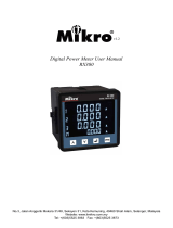
Figure 9, TC -Typical External Wiring Diagram, shows a typi-
cal wiring arrangement for all models.
Figure 10, TC - Detailed Drawing, shows a detailed descrip-
tion of mechanical connections for all models..
Figure 11, TC - Power and Discrete Input Wiring, shows alter-
native approaches for discrete input wiring (TC-100 only).
2.4.2 Wiring Procedures
Follow these procedures to wire all TC models.
2.4.2.1 Thermocouples
1. Connect the thermocouple wires to terminal block J2,
shown in Figure 10, TC - Detailed Drawing, as follows:
a. Connect Left Phase (A) (+) to terminal 1 and (-) to
terminal 2.
b. Connect Center Phase (B) (+) to terminal 3 and (-) to
terminal 4.
c. Connect Right Phase (C) (+) to terminal 5 and (-) to
terminal 6
d. Connect Ambient (+) to terminal 7 and (-) to terminal
8
ote:N The standard color code for K type thermocouple
wire is yellow insulation for the positive (+) lead and
red insulation for the negative (-) lead. For E type
thermocouple wire the standard is purple insulation
for the positive (+) lead and red insulation for the
negative (-) lead.
2.4.2.2 Trip Relay
1. Connect the trip contactor or coil to be controlled by
trip relays to terminal block J1, shown in Figure 10, as
follows:
a. Connect the trip relay Normally Closed (NC) cont act
to terminal #1.
b. Connect trip relay Common (COM) contact to termi-
nal #2.
c. Connect the trip relay Normally Open (NO) contact to
terminal #3.
ote:N The fail-safe setting for the trip relay will determine
the state of the NO and NC contacts. When fail-safe
mode is Off, the NO contact is open when no trip
condition is present or latched, and closes to NC
when a trip condition occurs. This is reversed when
fail-safe mode is On.
2.4.2.3 Alarm Relay
1. Connect remote alarm equipment to be controlled by
the alarm relay to terminal block J1, shown in Figure
10, TC - Detailed Drawing, as follows:
a. Connect equipment to the alarm relay Normally
Closed contact (NC) to terminal #4.
b. Connect the alarm relay Common contact (COM) to
terminal #5.
c. Connect the alarm relay Normally Open contact (NO)
to terminal #6.

9
Instruction Manual IM02602008E - Rev. D
Transformer Temperature Controllers IM02602008E - Rev. D May 2019 www.eaton.com
ote:N The fail-safe setting for the alarm relay will determine
the state of the NO and NC contacts. When fail-
safe mode is Off, the NO contact is open when no
alarm condition is present or latched, and closes to
NC when an alarm condition occurs. This is reversed
when fail-safe mode is On.
2.4.2.4 Earth Ground
1. Connect terminal #8 of terminal block J1, shown in
Figure 10, to the closest solid electrical-safety ground-
ing point with a heavy wire or braid (#14 AWG or
larger). Do not use a current-carrying or neutral conduc-
tor for this grounding. Also, do not tie terminal #8 to
neutral terminal #10 of terminal block J1.
2.4.2.5 100 Vac to 240 Vac Input Power
1. Connect terminals #7 and #10 of terminal block J1,
shown in Figure 10, to a source of control power rated
at 100 - 240 Vac.
a. Connect LINE to terminal #7
b. Connect NEUTRAL (120V) or Line 2 (240V) to termi-
nal #10.
2.4.2.6 Discrete Input Power (TC-100 Only)
The discrete inputs are used for sensing contacts on
remote relays or sensor switches for the purpose of gen-
erating alarm or trip conditions or controlling the fan(s) on
the TC-100. Note that programming of the discrete inputs
allows connection to either normally open (NO) or normally
closed (NC) contacts.
The Discrete Input circuits are isolated from the other cir-
cuits in the TC and have their own common connection,
Terminal 12. The contact signals are connected to Terminals
11 and 13.
Two methods of powering and connecting the customer
contacts are shown in Figure 11, “TC - Discrete Input Power
Wiring”.
1. Connect external contacts to the TC-100 discrete inputs
on terminal block J1, shown in Figure 10, as follows:
a. Connect a remote contact wetting source to one side
of the remote contact.
b. Connect the other side of the remote contact to ter-
minal 11 or 13.
c. Connect terminal 12 to the neutral or line 2 of that
remote source.
CAUTION
FOR NOISE IMMUNITY AND SAFETY, DO NOT CONNECT
THE DISCRETE COMMON TERMINAL 12 TO TERMINAL 10
OR ANY OTHER NEARBY NEUTRAL IF A REMOTE WET-
TING SOURCE IS IN USE.
CAUTION
BEWARE OF LARGE SHUNT CAPACITANCE ACROSS
CONTACTS OR IN SOLID-STATE RELAYS CONNECTED TO
THE TC-100 DISCRETE INPUTS. CHARGING CURRENT
THROUGH THE CAPACITOR COULD CAUSE A FALSE INDI-
CATION OF A CLOSED CONTACT. KEEP TOTAL CAPACI-
TANCE BELOW 0.05 MICROFARADS.
2.4.2.7 Modbus Network (TC-50 Modbus
and TC-100 only)
1. Connect the Modbus network to terminal block J8,
shown in Figure 9, TC - Typical External Wring Diagram,
as follows:
a. Connect (A) to terminal #4, and B to terminal #3.
b. Connect the (COM) to terminal #2.
c. Connect the Shield to terminal #1.
2.4.2.8 4-20mA Output
1. Connect the remote meter or SCADA system to the
4-20mA Output on terminal block J7, shown in Figure 9,
TC- Typical External Wiring Diagram, as follows:
a. Connect (+) to terminal #2.
b. Connect (-) to terminal #1.

10
Instruction Manual IM02602008E - Rev. D
Transformer Temperature Controllers IM02602008E - Rev. D May 2019 www.eaton.com
2.4.2.9 Fan Power
WARNING
POWER TO THE FAN(S) MUST BE FUSED AT THE SOURCE
AT A LEVEL APPROPRIATE FOR THE SELECTED WIRING.
1. Connect input power (line or +) for the fan(s) to termi-
nal #1, shown in Figure 9, TC - Typical External Wiring
Diagram.
2. Connect input power (line2, neutral, or -) for the fan(s) to
terminal #2.
3. Connect the passed-through output power (line2, neutral
or -) to the fan(s) to terminal #3.
4. Connect the fused, switched output power to the fan(s)
to terminal #4.
ote:N The fuses built into the TC-100 are standard 1/4” x
1-1/4”, 250 Vac, 20 Amps maximum rating. Lower rat-
ings may be used, as required, based upon the appli-
cation’s power supply, wire size, and fan(s).
2
3
4
5
6
7
8
9
10
11
12
13
Transformer
Temperature
Controller
1
2
3
4
1
J2
1
2
3
4
J8
J1
J7
J9
J10
(+) 2
(-) 1
1
2
3
4
1
2
3
4
5
6
7
8
FAN
POWER
FAN 1
FAN 2
BURDEN
<1K OHM
R
4-20mA
LOOP
Modbus
NETWORK
T
REMOTE TRIP
REMOTE ALARM
NON CURRENT
CARRYING GROUND
120/240VAC
CONTROL
POWER
TRIP/
ALARM
POWER
L
C
R
+
-
+
-
+
-
+
-
THERMOCOUPLES
in TRANSFORMER
WINDINGS
THERMOCOUPLE
in CABINET
AMBIENT AIR
4-20mA
OUTPUT
A
B
COMMON
Shield
THERMOCOUPLE INPUTS
RS-485 Modbus
MONITOR
(TC-50 Modus and
TC-100 Only)
Figure 9, TC - Typical External Wiring Diagram

11
Instruction Manual IM02602008E - Rev. D
Transformer Temperature Controllers IM02602008E - Rev. D May 2019 www.eaton.com
ALARM COM
2
ALARM N/O
3
TRIP N/C
4
5
6
TRIP N/O
TRIP COM
100V to 240V
7
EARTH GROUND
8
No Connect
9
NEUTRAL or 240V Line 2
10
DISCRETE INPUT 1
11
DISCRETE COM
12
DISCRETE INPUT 2
13
Transformer
Temperature
Controller
1
2
3
4
NEUTRAL INPUT
POWER INPUT
NEUTRAL OUTPUT
FUSED POWER OUTPUT
FAN 1
ALARM N/C
1
+
-
+
-
+
-
+
-
LEFT PHASE
CENTER PHASE
RIGHT PHASE
AMBIENT
THERMOCOUPLE
J2
1
2
3
4
NEUTRAL INPUT
POWER INPUT
NEUTRAL OUTPUT
FUSED POWER OUTPUT
FAN 2
J8
J1
A
B
COMMON
SHIELD
RS-485
Modbus
+
-
4-20mA
OUTPUT
J7
INPUT
POWER
J9
J10
(TC-50 Modbus
and TC-100 Only)
(TC-100 Only)
Figure 10, TC- Detailed Drawing

12
Instruction Manual IM02602008E - Rev. D
Transformer Temperature Controllers IM02602008E - Rev. D May 2019 www.eaton.com
NON-CURRENT
CARRYING GND.
CUSTOMER REMOTE
INPUT CONTACTS
OR PUSHBUTTONS
TRANSFORMER
CONTROL POWER
TRANSFORMER
CONTROL POWER
CUSTOMER REMOTE
OR PUSHBUTTONS
INPUT CONTACTS
REMOTE CONTACT
WETTING SUPPLY
100-240 VAC
2
3
4
5
6
7
8
9
10
11
12
13
TC-100
1
2
3
4
5
6
7
8
9
10
11
12
13
1
100-240 VAC
100-240 VAC
Figure 11, TC - 100 Discrete Input Power Wiring

13
Instruction Manual IM02602008E - Rev. D
Transformer Temperature Controllers IM02602008E - Rev. D May 2019 www.eaton.com
3. Operating Functions
NOTICE
FUNCTIONS DESCRIBED IN THIS SECTION ARE THE
SAME FOR ALL MODELS, UNLESS OTHERWISE STATED
IN A SUBJECT HEADING.
TC models boast a variety of functions. Some of them were
mentioned in the Introduction, but not explained in detail.
This section describes the Operating Functions of all TC
models in an organized manner. How you set up, program
and control each TC model to implement these functions is
explained in Section 4, Operating Procedures.
Operating functions of the TC models are organized into
four categories, as described below.
3.1 Monitoring
The TC models monitor and display the temperature of each
of the four thermocouples (Left, Center and Right Phases,
and the ambient temperature) on a continuing basis.
In the Scroll mode, the temperatures are displayed sequen-
tially on the LED display on the front panel, at 3 second
intervals. The display alternates between Left, Center, Right,
Ambient, Maximum Winding, and Average Winding tem-
peratures and shows the temperature of that thermocouple
in °C or °F. The value (°C or °F) is programmable.
In the Max mode, the highest of the three winding temper-
atures, alternating with the average of the winding tempera-
tures, will be displayed on a continuous basis.
The Scroll or Max mode is programmable.
3.2 Programming
Many control functions can be selected or changed by the
operator. This includes changing temperature setpoints
to modify fan turn-on, alarm and trip conditions, setting
parameters for gathering report information, and controlling
various functions on a (programmable) timed basis. The TC
models can also be programmed to operate (exercise) the
fans for short intervals to prevent seizing.
Programming the TC models Manually is done from the
front panel, using a variety of pushbuttons.
Entering the Program mode, using the
Prog
button,
presents a list of options from which you may select. You
can navigate through this list using the
and
arrows
(Up and Down arrows) until you find the option desired.
Pressing the
Select
button selects that option.
Sometimes, pressing
Select
will present another list of
options from which to choose. Navigate that list the same
as before, using the
and
arrows, then press the
Select
button to select (enter) that option.
How to set specific parameters is covered in sections 4.1.2,
Programming the TC Manually, and 4.1.2.2 Configuration
Parameters.
3.3 Reporting (TC-100 Only)
The TC models can automatically collect and store report
(log) data.
Typical reports (logs) include:
• Temperature Trend Data
• Alarm Log
• Trip Log
• Fan Wear History
Up to 100 points of Temperature Trend Data and 25 entries
each for Alarm and Trip Logs can be stored .
Individual logs are stored on a First In First Out (FIFO) basis,
where the oldest log is replaced by the newest.
Individual logs are displayed on a Last In First Out (LIFO)
basis, where the newest log is always displayed.
3.4 Testing
The TC allows the user to test various functions to assure
they are operating correctly. These include testing the fol-
lowing:
• Alarm and Trip relays
• Internal temperature of the TC
• LED display
• Individual LEDs
• Operation of buttons on the front panel.

14
Instruction Manual IM02602008E - Rev. D
Transformer Temperature Controllers IM02602008E - Rev. D May 2019 www.eaton.com
4. Operating Procedures
NOTICE
FUNCTIONS DESCRIBED IN THIS SECTION ARE THE
SAME FOR ALL MODELS, UNLESS OTHERWISE STATED
IN A SUBJECT HEADING.
TC models can be operated/programmed three different
ways::
• Manual Operation, using the front panel controls (all
models)
• Local Operation, using a laptop computer connected to
the TC USB port (all models)
• Remote Operation, using a standard Modbus communi-
cations network (TC-50 Modbus and TC-100 only).
Regardless of the operating method selected, each TC must
be set up or programmed to best suit the needs/desires of
the user.
The Reset and Test functions are only available in Manual
Operation using the front panel controls.
The programming functions of all TC models are the same,
regardless of the operating method used.
However, each operating method varies in its execution. For
this reason, each is described in a separate section, below.
4.1 Manual Operation
Operating the TC models manually, at the front panel,
requires a thorough understanding of the controls and
how they are used to set up/program the controller. These
controls are used to set up various operating parameters,
change setpoints, reset alarm and trip relays, and clear data
logs used for reports.
Some functions of the TC can be controlled manually by the
operator, such as turning the cooling fans On or Off, silenc-
ing alarms, and performing various test routines.
The content of this section is organized into four functional
areas:
• Control Functions
• Reset Functions
• Programming Functions
• Test Functions.
4.1.1 Control Functions
The front panel contains one 8-charcter LED display, nine
discrete LEDs, and nine pushbutton membrane switches.
Using the front panel controls, the user can set the TC for
automatic operation, establish setpoints, configure the sys-
tem, and set operating parameters.
The bottom of the front panel also contains one flip-up door,
which can be sealed with a locking wire, that covers a USB
2.0 port. The USB port is used to connect a laptop computer
to the TC to operate it Locally.
The front control panel layout is shown below, in Figure 12,
TC - Front Panel Controls.
The function of each front panel control is explained on the
following pages.
Figure 12, TC- Front Panel Controls

15
Instruction Manual IM02602008E - Rev. D
Transformer Temperature Controllers IM02602008E - Rev. D May 2019 www.eaton.com
4.1.1.1 LED Display:
The 8-character LED panel, shown above, displays a variety
of messages, including average and maximum tempera-
tures, setpoint values, status, and program menu items.
Specific messages that will be displayed are mentioned
throughout this manual, and notably in Section 4.1.2,
Operating the TC Manually.
The display can be set to operate in either of two modes:
• Scroll Mode: Displays each winding (and ambient) tem-
perature sequentially, allowing a few seconds to read
each value. Typical Scroll displays show the winding
temperature of Phase A, B, and C, then, the ambient
temperature, followed by the maximum measured wind-
ing temperature, and finally the average of the measured
winding temperatures. The sequence is then repeated.
At the same time, the corresponding temperature LED
indicator illuminates (as described in Section 4.1.1.2, LED
Indicators), for Phase A. B, C and Ambient. If one or more
alarms are present and alarm display is enabled, an abbre-
viated alarm description will also be displayed.
• Max Mode: Displays the value of the highest winding
temperature and the average of the winding tempera-
tures. The Temperature LED Indicator corresponding to
the winding with the maximum temperature illuminates
when the max temperature is displayed. If one or more
alarms are present and alarm display is enabled, an abbre-
viated alarm description will also display.
While in the Max mode, you can scroll through the phase
winding temperatures using the
and
arrows on the
front panel. After a 60 second time-out, the system returns
to the Max mode.
4.1.1.2 LED Indicators
4.1.1.2.1 Fan LED
A yellow LED Illuminates when one or both fan relays are
On.
4.1.1.2.2 Alarm LED
A red LED illuminates when the alarm relay is active due
to an over-temperature condition from any of the four ther-
mocouples, if there is a thermocouple failure, or an internal
failure of the TC.
4.1.1.2.3 Status LEDs
Red LEDs Indicate the operating status of the TC as follows:
• Trip LED: Illuminates when the trip relay is active.
• Program LED: Illuminates when the TC is in the manual
program mode, via the
Prog
button on the front panel.
• Test LED: Illuminates when the TC is in the test mode,
via the
Test
button on the front panel.
4.1.1.2.4 Temperature LEDs
Green LEDs Illuminate when the temperature of one of the
thermocouples is displayed on the LED screen, as follows:
• Left Phase: Indicates the temperature for this channel is
being displayed, in either °C or °F.
• Center Phase: Indicates the temperature for this channel
is being displayed, in either °C or °F.
• Right Phase: Indicates the temperature for this channel
is being displayed, in either °C or °F.
• Ambient: Indicates the temperature for this channel is
being displayed, in either °C or °F.
ote:N Displaying the temperatures in either °C or °F is pro-
grammable.
ote:N The label beside the Temperature LED Indicators may
be removed and turned over to provide a place for
the user to write their own description. The best way
to remove the label is to slide a sticky note, sticky
side facing up, under the label and then carefully
remove the label with the sticky note.

16
Instruction Manual IM02602008E - Rev. D
Transformer Temperature Controllers IM02602008E - Rev. D May 2019 www.eaton.com
4.1.1.3.3 Fan
The
Fan
button turns the fans On or Off, if manual opera-
tion is enabled, but has no effect if manual operation is
disabled.
In the Auto/Manual mode,
Fan
turns the fans On, but
will not turn the fans Off if the thermocouple temperatures
are above the programmed setpoint.
4.1.1.3.4 Alarm
The
Alarm
button silences the audible alarm (if enabled)
when an alarm is present.
Alarm
has no effect if audible
alarm is disabled.
If there is no alarm condition, pressing
Alarm
tests the
alarm and cause it to sound. Pressing
Alarm
again silenc-
es the alarm.
Alarms can be set to be latched or unlatched, (Latched
means that even if you correct the alarm condition, the
alarm will remain until manually reset).
If an alarm is initiated, the TC-100 creates a data log by col-
lecting data about the type of alarm, the time and date of
the alarm, and the temperature of each thermocouple at the
time of the alarm. The TC-100 stores such alarm data for up
to 25 alarms.
Alarm conditions include:
• Temperature not decreasing
• Thermocouple Reverse Connection
• Thermocouple Open Circuit.
• Winding over-temperature
• Air flow not detected
• Fan wear limit time exceeded
• Maximum fan on time exceeded
Alarm Internal Controller Failures include:
• EEPROM Failure
• FRAM Failure
• Isothermal Block out of range
4.1.1.3 Pushbutton Controls:
4.1.1.3.1 Password Protection
Three pushbuttons are password protected:
Reset
,
Prog
, and
Test
. A valid four character, alpha-numeric
password must be entered for these pushbuttons to func-
tion.
The TC models are shipped with the default password of
“0000”. When a password protected button is pressed, the
LED display shows PWD**.** prompting you to enter your
password.
Changing the password is optional.
If the default password has not been changed, simply press
Select
to enter the Reset, Program, and Test programs.
If the default password has been changed, the new pass-
word must be entered to access the program.
Enter the password as follows:
1. Press the
arrow to change the individual password
character; (0 through 9 and A through F). Press the
arrow to move to the next character in the display.
2. Press
Select
to enter the password.
3. If the password is correct, the LED display will show
the first item in the Reset, Program, or Test sub- menu
depending on the function being accessed.
4.1.1.3.2 Reset
ote:N The
Reset
button is password protected. See
Section 4.1.1.3.1 Password Protection.
The
Reset
button is located at the very top of the front
panel, to the right. This button allows the user to:
• Reset alarm and trip relays that are latched.
• Clear trend, alarm, trip or fan wear data logs (TC-100
Only).
The various reset functions are described in Section 4.1.2.1,
Reset Functions, and shown in Appendix B, Programming
Quick Reference Guide, Table 1.
Note: The
Reset
button is password protected. See
Section 4.1.1.3.1, Password Protection.
/