Page is loading ...

Digital Power Meter User Manual
RX380
No.3, Jalan Anggerik Mokara 31/48, Seksyen 31, Kota Kemuning, 40460 Shah Alam, Selangor, Malaysia
Website: www.itmikro.com.my
Tel: +(603)5525 3863 Fax: +(603)5525 3873
v1.2

HAZARD CATAGORIES AND SPECIAL SYMBOL
Read all instruction carefully and check the device before installing or servicing it. The following safety alert
symbol may appear throughout this manual or on the device to warn of any potential hazards or to call for
attention.
PLEASE NOTE
The power meter should be installed, operated, serviced and maintained only by qualied personnel. No
responsibility is assumed by the manufacturer for any consequences arising out of the use of this material.
DISCLAIMER
Mikro shall not be liable for errors contained herein including any incidental and/or consequential damages
arising from the use of this material. Mikro also reserves the right to vary the product from that described in this
material without prior notice.
COPYRIGHT
The licensed software contained in the product is proprietary software owned by Mikro or its third party suppliers
and shall be used solely in connection with the product.
BEFORE YOU BEGIN
• Apply appropriate personal protective equipment and follow safe electrical work practices.
• NEVER work alone.
• Turn o all power supplying the power meter and the equipment in which it is installed before working
on it.
• Always use a properly rated voltage sensing device to conrm that all power is o.
• Before closing all covers and doors, carefully inspect the work area for tools and objects that may have
been left inside the equipment.
• NEVER bypass external fusing.
• NEVER open circuit a CT; use the shorting block to short circuit the leads of the CT before removing
the connection from the power meter.
• Before performing hi-pot testing on any equipment in which the power meter is installed, disconnect all
input and output wires to the power meter. High voltage testing may damage electronic components
contained in the power meter.
• The power meter should be installed in a suitable electrical enclosure.
Failure to follow this instruction may result in serious injury

CONTENTS
1. Introduction
1.1. Content of box
1.2. Part of power meter
2. Installation Guide
2.1. Precautions
2.2. Mounting
2.3. Wiring
3. Meter parameters
4. Display and Buttons
5. Function
6. Setting up
6.1. Access programming mode
6.2. Setup CT ratio
6.3. Setup PT ratio
6.4. Neutral current
6.5. Setup communication conguration
6.6. Demand setting
6.7. System setting
6.8. Reset all energy register
6.9. Reset demand register
6.10. Reset maximum & minimum value
6.11. Remote set
6.12. Scroll setting
6.13 Scroll delay setting
6.14 Reset Hour on register
6.15 Backlight setting
6.16 Software version
6.17 Exit from programming mode
6.18 Setup new password
7. Specications
8. Modbus Data Register
1
1
2
3
3
3
4
6
6
7
9
9
10
10
11
11
12
12
13
13
14
14
15
15
16
16
16
17
17
18
20

9. Maintenance and Troubleshooting
10. Dimensions
11. Appendix
11.1. Demand Calculation
11.2. Data Read Format from Modbus
11.3. Neutral Current Calculation
29
29
30
30
30
31
FIGURES
1. Parts of power meter
2. Recommended cut-out
3. 3-phase 4-wire system with 4 CTs
4. 3-phase 4-wire system with 3 CTs
5. 3-phase 3-wire with 3CTs and 3VTs
6. 3-phase 3-wire with 2CTs and 3VTs
7. Menu map for the normal mode
8. Flow map for the programming mode
2
3
4
4
5
5
7
8
TABLE
1. Parts list
2. Location and part label
3. Model information
4. Specication
5. Data length nomenclature
6. Device and communication register
7. Operation data registers
8. Setting data registers
1
2
2
18
20
20
21
28

1. Introduction
Thank you for purchasing the RX380 Digital Power Meter. This multifunctional power meter measures the
following parameters:
• True RMS phase voltage ( L - N )
• True RMS line voltage ( L - L )
• True RMS phase and neutral current
• Positive and negative maximum and minimum active and reactive power
• Maximum and minimum apparent power
• Total active, reactive and apparent energy
• Total and displacement power factor
• Frequency
• Voltage and current total harmonic distortion (THD)
• Demand and maximum demand for total real, reactive and apparent power
• Maximum and minimum phase and line voltage
• Maximum and minimum phase and neutral current
• Positive and negative maximum and minimum total active, reactive and apparent power
This power meter also comes with the Modbus-RTU connectivity.
1.1. CONTENT OF BOX
Upon opening this box, you should nd the following item shown in table 1:
Table 1: Parts list
No Description Quantity
1 RX380 power meter 1
2 Retainer clip 2
3 Quick guide 1

2
Model Information
RX380 Auxiliary 90~415VAC or 100~300VDC; with Modbus
Table 3: Model information
1
2
3
4
5
5
6
6
1.2. PARTS OF POWER METER
Figure 1: Parts of power meter
No Part Description
1 Current inputs Current metering connections
2 RS485 port The RS485 port is used for communications with remote monitoring and
control system
3 Power supply input Connection to power the meter
4 Voltage inputs Voltage metering connections
5 Retainer clips Used to hold power meter in place.
6 Retainer clips slot To slot-in retainer clips in place
Table 2: Location and part label

3
2.2. MOUNTING
Figure 2:
Recommended cut-out.
2. Installation Guide
Before installing the power meter, please check that the environment meets the following condition:
• Operating temperature -10 Celcius to +55 Celcius.
• Humidity 5% to 95%, non-condensing
• Dust free environmental away from electrical noise and radiation
2.1. PRECAUTIONS
91 ± 0.5mm
91 ± 0.5mm
a) Provide a cut out hole on the switchgear panel according to the
dimension below.
b) Insert the power meter through the hole and slide in the retainer clip
along the slots on left and right sides or bottom and top sides of the
power meter until the device is tightly secured on the switchgear panel.
The orientation of the retainer clips is shown in Figure 1.
The retainer clip can be removed by lifting the tab lightly at the handle
end.
c) Connect the metering voltage input, current input, communication and
auxiliary according to the wiring schemes shown in Section 2.3, Figure
3 to 6 on the next page.
d) The recommended wire size is as below:
• Voltage input and auxiliary - AWG16~22
• Current input - AWG12~18
• Modbus-RTU - AWG22 or thicker, shielded twisted pair
NOTE:
Polarity marks must be followed as shown for CTs (S1 and S2). Please make sure the
power to the current metering input is totally shunted. Under no circumstances can the CT
connection be left in open circuit. Use a CT shorting block if necessary.
e) When connecting the power meter, please make sure the polarity to the terminal is correctly aligned.
f) If the Modbus-RTU is used, it can be connected up to 32 devices in a daisy chain fashion and the cable total
length should not be more than 1000m.
NOTE:
For Modbus-RTU connection, avoid running the cable near sources of electrical noise. The
network cable shield should be grounded at only one end.

4
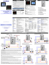
Figure 3: 3 Phase 4-Wire System with 4CTs connection, direct voltage input.
2.3. WIRING
19
20
1
2
3
4
5
6
7
8
15
16
17
18
14
13
12
Figure 4: 3-Phase 4-Wire System with 3CTs connection, direct voltage input.
NOTE:
Neutral current measurement is based on the vector sum of 3 CTs.
19
20
1
2
3
4
5
6
7
8
15
16
17
18
14
13
12

5
Figure 5 : 3-phase 3-wire with 3CTs and 3VTs connection.
19
20
1
2
3
4
5
6
7
8
15
16
17
18
14
13
12
Figure 6: 3-phase 3-wire with 2CTs and 3VTs connection.
NOTE:
I2 current measurement is based on the vector sum of 2 CTs.
19
20
1
2
3
4
5
6
7
8
15
16
17
18
14
13
12

6
3. Meter parameters
Before commencing operation, the meter has to be set up. To do this, the meter must be powered up by the
meter control power supply.
Under Section 6, the following parameters should be reviewed against the default value if necessary:
• CT Ratio
• PT Ratio
• Neutral current input
• Modbus-RTU setting
• Demand setting
• System setting
• Remote Set
• Scroll mode setting and delay time
• Backlight setting
The ow maps for the meter is under Section 5. It is guideline for the user to ip to the desire window whether in
normal mode or programming mode.
4. Display and Buttons
a. Setting Indicator
b. Total Indicator
c. Alarm Indicator
d. Percentage Indicator
e. Phase Sequence Error Indicator
f. Unit Indicator
g. Capacitive/Inductive Indicator
h. Digit Display
i. ‘PROG’ button
j. ‘NEXT’ button
k. ‘DOWN’ button
l. ‘UP’ button
m. Phase Indicator
n. Window Indicator
a
b
c
d
e
f
g
h
i
j
k
m
n
NOTE:
In case of current/voltage phase loss or phase sequence error, both Alarm Indicator (c) and Phase
Sequence Error Indicator (e) will blink
l
RX 380
DIGITAL POWER METER

7
Figure 7 below shows menu map for the power meter. It includes the setting and measurement display for the
power meter. These menus can be accessed by pressing NEXT, UP, PROG & DOWN buttons.
5. Function
Figure 7 : Menu map for normal mode.
Line Current (A) Min. Current
(A)
Max Current
(A)
Line Voltage (V) Phase
Voltage (V)
Min. Line
Voltage (V)
Min. Phase
Voltage (V)
Max Line
Voltage (V)
Max Phase
Voltage (V)
Power Factor (PF) &
Frequency (Hz)
True Power
Factor (PF)
Displacement Power
Factor (DPF)
Total Power
(W, VAR, VA)
Positive Min. Total
Power
(W, VAR, VA)
Negative Min. Total
Power
(W, VAR, VA)
Positive Max Total
Power
(W, VAR, VA)
Negative Max Total
Power
(W, VAR, VA)
Real Power
(W)
Positive Min. Real
Power
(W)
Negative Min. Real
Power
(W)
Positive Max Real
Power
(W)
Negative Max Real
Power
(W)
Positive Min.
Reactive Power
(VAR)
Negative Min.
Reactive Power
(VAR)
Positive Max
Reactive Power
(VAR)
Negative Max
Reactive Power
(VAR)
Reactive Power
(VAR)
Positive Min.
Apparent Power
(VA)
Negative Min.
Apparent Power
(VA)
Positive Max
Apparent Power
(VA)
Negative Max
Apparent Power
(VA)
Apparent Power
(VA)
Demand
(W, VAR, VA)
Max. Demand
(W, VAR, VA)
Total Neg. Real
Energy
(-kWh)
Total Reactive
Energy
(kVARh)
Total Neg. Reactive
Energy
(-kVARh)
Total Apparent
Energy
(kVAh)
Total Real Energy
(kWh)
THD Current
(A)
THD Voltage
(V)
Hour On
(Days, Hours, Mins)

8
Figure 8 : Menu map for programming mode
PROG Mode
CT Ratio
Setting (A)
To change value range 5 - 9999A
for primary and 5A for secondary
PT Ratio
Setting (V)
Neutral Current
Setting (Ln)
Reset (Yes/No)
Reset Demand
Register Reset (Yes/No)
Scroll Display
Setting To scroll display in idle mode (ON/OFF)
Demand
Setting
Reset
Max/Min Reset (Yes/No)
System Setting
Scroll Delay
Time To set interval time for scroll display (1-10secs)
Reset Hour-
On Register Reset (Yes/No)
Backlight
Setting
Setup Communication
Conguration
Display Neutral Current
(Measure / Calculate / Off)
Remote Set
Reset All
Energy Register
To change value range 100 - 33kV for
primary and 100 - 250V for secondary
To turn off backlight after minutes of idle (ON/OFF)
Software
Version
(ON/OFF)

9
The power meter comes with factory default settings. These values may be changed by navigating to the
appropriate screens and entering new values. Use the instructions in the following sections to change the values.
a. Press the PROG button to enter programming mode. The rst number will blink to enter password.
b. Use the UP or DOWN button to change display value and the NEXT button to shift to next number.
c. Press the PROG button to conrm and enter programming mode. Setup CT ratio will be display. If the
password is incorrect, the meter will return to normal mode.
d. To exit press the PROG button and display will return to normal mode.
6.1. ACCESS PROGRAMMING MODE
6. Setting up
NOTE:
Default password is “0000”
6.2. SETUP CT RATIO
a. CT ratio setting is the rst item displayed in programming mode.
b. Press the NEXT button to change. The rst digit will blink.
c. Use the UP or DOWN button to change the primary CT value.
d. Press the NEXT button for the next digit. Repeat step (b) & (c) to change, or else press PROG button to save
the setting.
e. The SAVE window will be prompted. Use the UP or DOWN button to select “YES” or “NO”. Press the PROG
button to conrm.
f. To proceed next setting press DOWN button. To exit programming mode, press the PROG button. Refer
Section 6.17.
NOTE:
CT Ratio default value is 5/5A

10
6.3. SETUP PT RATIO
NOTE:
PT Ratio default value is 100/100V
6.4. NEUTRAL CURRENT
a. Scroll in programming mode until “Ln” is displayed using the UP or DOWN button.
b. This parameter is to display neutral current if the neutral current (Ln) is connected.
c. Press the NEXT button to change. The “PROG” symbol will blink.
d. Press the UP or DOWN button to toggle the symbol “cAL” for calculated value, “MEA” for measured value
or “OFF” to disable.
e. Press the NEXT button to conrm the new setting.
f. The SAVE window will be prompted. Press the UP or DOWN button to select “YES” or “NO”. Press the PROG
button to conrm.
g. Use the DOWN button to scroll to next setting.
h. To exit programming mode, refer Section 6.17.
NOTE:
Neutral current default setting is measured value
a. Scroll in programming mode until “Pt” is displayed using the UP or DOWN button.
b. This parameter is to change the PT value if the Power Transformer (PT) is connected.
c. Press the NEXT button to change. The “V” symbol for primary will blink.
d. Press the UP or DOWN button to change the value of setting.
e. Press the NEXT button to conrm the new setting and proceed for secondary setting.
f. Repeat step (c) & (d) to change for secondary. Once conrmed, press the NEXT button again.
g. The SAVE window will be prompted. Press the UP or DOWN button to select “YES” or “NO”. Press the PROG
button to conrm.
h. Use the DOWN button to scroll to next setting.
i. To exit programming mode, refer Section 6.17.

11
6.5. SETUP COMMUNICATION CONFIGURATIONS
a. Scroll until ”ID BRATE PARITY“ is displayed using the UP or DOWN button.
b. Press the NEXT button. The “PROG” and “-” symbol next to “ID” will blink. Use the UP or DOWN button to
change the device ID.
c. Next, press the NEXT button and “-” symbol next to “BRATE” will blink to change baudrate. Repeat step (b)
to change.
d. Press NEXT button to change parity and “-” symbol next to “PARITY” will blink. Repeat step (b) to change.
e. Then press the NEXT button to conrm new setting.
f. The SAVE window will be prompted. Press the UP or DOWN button to select “YES” or “NO”. Press the PROG
button to conrm.
g. Use the DOWN button to scroll to next setting.
h. To exit programming mode, refer Section 6.17.
NOTE:
Default value for the communication ID is 1, baudrate is 38400 bps and parity set to no-1 (parity
none, stop bit 1).
a. Scroll until ”DMD“ is displayed using the UP or DOWN button.
b. Press the NEXT button to change interval value. The “PROG” symbol will displayed and “-” symbol next to
“INT” will blink.
c. Use UP or DOWN button to change value and press NEXT button to conrm and change sub-interval setting.
The “-” symbol next to “SUB” will blink. Press UP or DOWN button to change and NEXT button to conrm.
d. The SAVE window will be prompted. Press the UP or DOWN button to select “YES” or “NO”. Press the PROG
button to conrm.
e. Use the DOWN button to scroll to next setting
f. To exit programming mode, refer Section 6.17.
6.6. DEMAND SETTING
NOTE:
Demand setting default value is 60/4

12
a. Scroll in programming mode until ”SYSt sEt“ is displayed using the UP or the DOWN button.
b. Press the NEXT button. The “PROG” symbol will blink. Use the UP or DOWN button to toggle 3-phase 4-wire
“3P4r” or 3-phase 3-wire “3P3r” symbols.
c. Press the NEXT button to conrm new setting.
d. The SAVE window will be prompted. Press the UP or DOWN button to select “YES” or “NO”. Press the PROG
button to conrm.
e. Use the DOWN button to scroll to next setting.
f. To exit programming mode, refer Section 6.17.
6.7. SYSTEM SETTING
NOTE:
System setting default value is 3-phase 4-wire
a. Scroll in programming mode until ”EnEr rSt“ is displayed using the UP or the DOWN button.
b. Press the NEXT button. The “PROG” symbol will blink. Use the UP or DOWN button to toggle “yES” or “no”
symbols.
c. To abort clearing energy register values, select “no”. To clear all energy values select “yES”.
d. Press the NEXT button to conrm the new setting.
e. The rSt dAtA window will be prompted. Press the UP or DOWN button to select “YES” or “NO”. Press the
PROG button to conrm.
f. Use the DOWN button to scroll to next setting.
g. To exit programming mode, refer Section 6.17.
6.8. RESET ALL ENERGY REGISTER

13
a. Scroll in programming mode until ”dMd rSt“ is displayed using the UP or the DOWN button.
b. Press the NEXT button. The “PROG” symbol will blink. Use the UP or DOWN button to toggle “yES” or “no”
symbols.
c. To abort clearing demand register, select “no”. To clear all demand register select “yES”.
d. Press the NEXT button to conrm the new setting.
e. The rSt dAtA window will be prompted. Press the UP or DOWN button to select “YES” or “NO”. Press the
PROG button to conrm.
f. Use the DOWN button to scroll to next setting.
g. To exit programming mode, refer Section 6.17.
6.9. RESET DEMAND REGISTER
a. Scroll until ”rSEt“ is displayed using the UP or the DOWN button.
b. Press the NEXT button. The “PROG” symbol will blink. Use the UP or DOWN button to toggle “yES” or “no”
symbols.
c. To abort clearing max. and min. values, select “no”. To clear all max. and min. values select “yES”.
d. Press the NEXT button to conrm new setting.
e. The rSt dAtA window will be prompted. Press the UP or DOWN button to select “YES” or “NO”. Press the
PROG button to conrm.
f. Use the DOWN button to scroll to next setting.
g. To exit programming mode, refer Section 6.17.
6.10. RESET MAXIMUM AND MINIMUM VALUE

14
a. Scroll until ”rMt SEt“ is displayed using the UP or the DOWN button.
b. Press the NEXT button. The “PROG” symbol will blink. Use the UP or DOWN button to toggle Enable “on”
or disable “oFF” symbols.
c. Press the NEXT button to conrm new setting.
d. The SAVE window will be prompted. Press the UP or DOWN button to select “YES” or “NO”. Press the PROG
button to conrm.
e. Use the DOWN button to scroll to next setting.
f. To exit programming mode, refer Section 6.17.
6.11. REMOTE SET
NOTE:
Enabling the remote set allows the remote terminal to read and write the meter setting via Modbus-RTU,
otherwise the setting data can only be read. Default value is ON.
a. Scroll in programming mode until ”Scrl SEt“ is displayed using the UP or the DOWN button.
b. This function is to turn ON/OFF scroll mode. If turn on, when the display is idle the meter will shows each
window in normal mode base on the scroll delay setting time.
c. Press the NEXT button. The “PROG” symbol will blink. Use the UP or DOWN button to toggle “oFF” or “on”
symbols.
d. Press the NEXT button to conrm the new setting.
e. The SAVE window will be prompted. Press the UP or DOWN button to select “YES” or “NO”. Press the PROG
button to conrm.
f. Use the DOWN button to scroll to next setting.
g. To exit programming mode, refer Section 6.17.
6.12. SCROLL SETTING
NOTE:
Scroll setting default value is OFF

15
a. Scroll in programming mode until ”Scrl dELY“ is displayed using the UP or the DOWN button.
b. This function is to set time interval for scroll window.
c. Press the NEXT button. The “PROG” symbol will blink. Use the UP or DOWN button to set 1sec to 10secs
interval.
d. Press the NEXT button to conrm the new setting.
e. The SAVE window will be prompted. Press the UP or DOWN button to select “YES” or “NO”. Press the PROG
button to conrm.
f. Use the DOWN button to scroll to next setting.
g. To exit programming mode, refer Section 6.17.
6.13. SCROLL DELAY SETTING
NOTE:
Scroll delay time default value is 10 seconds.
a. Scroll in programming mode until ”Hron rSt“ is displayed using the UP or the DOWN button.
b. This function is to clear hour-on register.
c. Press the NEXT button. The “PROG” symbol will blink. Use the UP or DOWN button to toggle “yES” or “no”
symbols.
d. To abort clearing hour-on register, select “no”. To clear hour-on register select “yES”.
e. Press the NEXT button to conrm the new setting.
f. The rSt dAtA window will be prompted. Press the UP or DOWN button to select “YES” or “NO”. Press the
PROG button to conrm.
g. Use the DOWN button to scroll to next setting.
h. To exit programming mode, refer Section 6.17.
6.14. RESET HOUR-ON REGISTER

16
a. Scroll in programming mode until ”bcLt“ is displayed using the UP or the DOWN button.
b. This function is to turn o backlight after 5 minutes idle.
c. Press the NEXT button. The “PROG” symbol will blink. Use the UP or DOWN button to toggle “oFF” or “on”
symbols.
d. Press the NEXT button to conrm the new setting.
e. The SAVE window will be prompted. Press the UP or DOWN button to select “YES” or “NO”. Press the PROG
button to conrm.
f. Use the DOWN button to scroll to next setting.
g. To exit programming mode, refer Section 6.17.
6.15. BACKLIGHT SETTING
NOTE:
Backlight setting default value is oFF
a. Use the PROG button exit from programming mode window. The line current window will be displayed.
If PROG
button is
pressed
6.17. EXIT FROM PROGRAMMING MODE
6.16. SOFTWARE VERSION
a. Scroll in programming mode until “SoFt VEr” is displayed using the UP or the DOWN button.
b. This window will display the current rmware version of the device.
c. Use the DOWN button to scroll to next setting.
d. To exit programming mode, refer Section 6.17.
/