
Eaton Power Distribution Rack (PDR)
208V
User’s Guide
®

Eaton, Powerware, Cutler−Hammer, Power Xpert, and X−Slot are registered trademarks of Eaton Corporation or its subsidiaries and affiliates.
Modbus is a registered trademark of Schneider Electric. National Electrical Code and NEC are registered trademarks of National Fire Protection
Association, Inc. All other trademarks are property of their respective companies.
ECopyright 2008 Eaton Corporation, Raleigh, NC, USA. All rights reserved. No part of this document may be reproduced in any way without the
express written approval of Eaton Corporation.

Class A EMC Statements
FCC Part 15
NOTE This equipment has been tested and found to comply with the limits for a Class A digital device, pursuant to part 15 of the FCC Rules. These
limits are designed to provide reasonable protection against harmful interference when the equipment is operated in a commercial environment.
This equipment generates, uses, and can radiate radio frequency energy and, if not installed and used in accordance with the instruction manual,
may cause harmful interference to radio communications. Operation of this equipment in a residential area is likely to cause harmful interference in
which case the user will be required to correct the interference at his own expense.
ICES−003
This Class A Interference Causing Equipment meets all requirements of the Canadian Interference Causing Equipment Regulations ICES-003.
Cet appareil numérique de classe A respecte toutes les exigences du Reglement sur le matériel brouilleur du Canada, ICES-003.
Requesting a Declaration of Conformity
Units that are labeled with a CE mark comply with the following harmonized standards and EU directives:
S Harmonized Standards: IEC 61000−3−12, IEC 60950−1:2001
S EU Directives: 2006/95/EC, Council Directive on equipment designed for use within certain voltage limits
2004/108/EC, Council Directive relating to electromagnetic compatibility
The EC Declaration of Conformity is available upon request for products with a CE mark. For copies of the EC Declaration of Conformity, contact:
Eaton Power Quality Oy
Koskelontie 13
FIN−02920 Espoo
Finland
Phone: +358−9−452 661
Fax: +358−9−452 665 68

Special Symbols
The following are examples of symbols used on the product to alert you to important information:
RISK OF ELECTRIC SHOCK − Observe the warning associated with the risk of electric shock symbol.
CAUTION: REFER TO OPERATOR’S MANUAL − Refer to your operator’s manual for additional information, such
as important operating and maintenance instructions.
This symbol indicates that you should not discard the product in the trash. This product must be disposed
of properly. For more information, contact your local recycling/reuse or hazardous waste center.
This symbol indicates that you should not discard waste electrical or electronic equipment (WEEE) in the
trash. For proper disposal, contact your local recycling/reuse or hazardous waste center.

EATON Power Distribution Rack (208V) User’s Guide S 164201720 Rev 1 www.powerware.com
i
Table of Contents
1 Introduction 1. . . . . . . . . . . . . . . . . . . . . . . . . . . . . . . . . . . . . . . . . . . . . . . . . . . . . . . .
2 Safety Warnings 5. . . . . . . . . . . . . . . . . . . . . . . . . . . . . . . . . . . . . . . . . . . . . . . . . . . .
3 Installation 7. . . . . . . . . . . . . . . . . . . . . . . . . . . . . . . . . . . . . . . . . . . . . . . . . . . . . . . .
Inspecting the Equipment 7. . . . . . . . . . . . . . . . . . . . . . . . . . . . . . . . . . . . . . . . . . . . . . . . . . . . . . . . . . . . . .
Tools Required 7. . . . . . . . . . . . . . . . . . . . . . . . . . . . . . . . . . . . . . . . . . . . . . . . . . . . . . . . . . . . . . . . . . . . .
Planning the Cabinet Location 8. . . . . . . . . . . . . . . . . . . . . . . . . . . . . . . . . . . . . . . . . . . . . . . . . . . . . . . . . . .
Unpacking the Cabinet 9. . . . . . . . . . . . . . . . . . . . . . . . . . . . . . . . . . . . . . . . . . . . . . . . . . . . . . . . . . . . . . . .
Checking the Accessory Kit 10. . . . . . . . . . . . . . . . . . . . . . . . . . . . . . . . . . . . . . . . . . . . . . . . . . . . . . . . . . . . .
Preparing the Cabinet 10. . . . . . . . . . . . . . . . . . . . . . . . . . . . . . . . . . . . . . . . . . . . . . . . . . . . . . . . . . . . . . . . .
Moving the Cabinet to its Final Location 10. . . . . . . . . . . . . . . . . . . . . . . . . . . . . . . . . . . . . . . . . . . . . . . . . . . .
Installing the PDR 12. . . . . . . . . . . . . . . . . . . . . . . . . . . . . . . . . . . . . . . . . . . . . . . . . . . . . . . . . . . . . . . . . . .
Removing the Solid Side Panel 12. . . . . . . . . . . . . . . . . . . . . . . . . . . . . . . . . . . . . . . . . . . . . . . . . . . . . . . .
Removing the Side Panel with Breakers 13. . . . . . . . . . . . . . . . . . . . . . . . . . . . . . . . . . . . . . . . . . . . . . . . .
Removing the Exterior Doors and Interior Barriers 16. . . . . . . . . . . . . . . . . . . . . . . . . . . . . . . . . . . . . . . . . .
Wiring Input and Output Power 18. . . . . . . . . . . . . . . . . . . . . . . . . . . . . . . . . . . . . . . . . . . . . . . . . . . . . . .
Initial Startup 32. . . . . . . . . . . . . . . . . . . . . . . . . . . . . . . . . . . . . . . . . . . . . . . . . . . . . . . . . . . . . . . . . . . .
Replacing the Interior Barriers, Exterior Doors, and Side Panels 33. . . . . . . . . . . . . . . . . . . . . . . . . . . . . . . . .
Completing the Installation Checklist 34. . . . . . . . . . . . . . . . . . . . . . . . . . . . . . . . . . . . . . . . . . . . . . . . . . .
4 Operation 35. . . . . . . . . . . . . . . . . . . . . . . . . . . . . . . . . . . . . . . . . . . . . . . . . . . . . . . . . .
Control Panel Functions 35. . . . . . . . . . . . . . . . . . . . . . . . . . . . . . . . . . . . . . . . . . . . . . . . . . . . . . . . . . . . . . .
EMS Meter Levels 36. . . . . . . . . . . . . . . . . . . . . . . . . . . . . . . . . . . . . . . . . . . . . . . . . . . . . . . . . . . . . . . .
Display Functions 36. . . . . . . . . . . . . . . . . . . . . . . . . . . . . . . . . . . . . . . . . . . . . . . . . . . . . . . . . . . . . . . . .
Menu Map 37. . . . . . . . . . . . . . . . . . . . . . . . . . . . . . . . . . . . . . . . . . . . . . . . . . . . . . . . . . . . . . . . . . . . . .
Setup Options 38. . . . . . . . . . . . . . . . . . . . . . . . . . . . . . . . . . . . . . . . . . . . . . . . . . . . . . . . . . . . . . . . . . .
Surge Protection Option 38. . . . . . . . . . . . . . . . . . . . . . . . . . . . . . . . . . . . . . . . . . . . . . . . . . . . . . . . . . . . . . .
Initial Configuration 39. . . . . . . . . . . . . . . . . . . . . . . . . . . . . . . . . . . . . . . . . . . . . . . . . . . . . . . . . . . . . . . . . .
EMS System Level Monitoring 39. . . . . . . . . . . . . . . . . . . . . . . . . . . . . . . . . . . . . . . . . . . . . . . . . . . . . . . .
EMS Branch Circuit Monitoring System 39. . . . . . . . . . . . . . . . . . . . . . . . . . . . . . . . . . . . . . . . . . . . . . . . . .
Side Breaker Access 39. . . . . . . . . . . . . . . . . . . . . . . . . . . . . . . . . . . . . . . . . . . . . . . . . . . . . . . . . . . . . . . . . .
Startup and Shutdown 40. . . . . . . . . . . . . . . . . . . . . . . . . . . . . . . . . . . . . . . . . . . . . . . . . . . . . . . . . . . . . . . .
Startup 40. . . . . . . . . . . . . . . . . . . . . . . . . . . . . . . . . . . . . . . . . . . . . . . . . . . . . . . . . . . . . . . . . . . . . . . .
Shutdown 40. . . . . . . . . . . . . . . . . . . . . . . . . . . . . . . . . . . . . . . . . . . . . . . . . . . . . . . . . . . . . . . . . . . . . .
5 Maintenance 41. . . . . . . . . . . . . . . . . . . . . . . . . . . . . . . . . . . . . . . . . . . . . . . . . . . . . . .
Important Safety Instructions 41. . . . . . . . . . . . . . . . . . . . . . . . . . . . . . . . . . . . . . . . . . . . . . . . . . . . . . . . . . .
Preventive Maintenance 41. . . . . . . . . . . . . . . . . . . . . . . . . . . . . . . . . . . . . . . . . . . . . . . . . . . . . . . . . . . . . . .
DAILY Maintenance 41. . . . . . . . . . . . . . . . . . . . . . . . . . . . . . . . . . . . . . . . . . . . . . . . . . . . . . . . . . . . . . .
PERIODIC Maintenance 41. . . . . . . . . . . . . . . . . . . . . . . . . . . . . . . . . . . . . . . . . . . . . . . . . . . . . . . . . . . . .
ANNUAL Maintenance 41. . . . . . . . . . . . . . . . . . . . . . . . . . . . . . . . . . . . . . . . . . . . . . . . . . . . . . . . . . . . .
Updating the Firmware 42. . . . . . . . . . . . . . . . . . . . . . . . . . . . . . . . . . . . . . . . . . . . . . . . . . . . . . . . . . . . . . . .
Short Circuits 42. . . . . . . . . . . . . . . . . . . . . . . . . . . . . . . . . . . . . . . . . . . . . . . . . . . . . . . . . . . . . . . . . . . . . .
Storage 42. . . . . . . . . . . . . . . . . . . . . . . . . . . . . . . . . . . . . . . . . . . . . . . . . . . . . . . . . . . . . . . . . . . . . . . . . . .
Recycling the Used PDR 42. . . . . . . . . . . . . . . . . . . . . . . . . . . . . . . . . . . . . . . . . . . . . . . . . . . . . . . . . . . . . . .

TABLE OF CONTENTS
EATON Power Distribution Rack (208V) User’s Guide S 164201720 Rev 1 www.powerware.com
ii
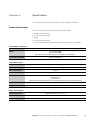
6 Specifications 43. . . . . . . . . . . . . . . . . . . . . . . . . . . . . . . . . . . . . . . . . . . . . . . . . . . . . .
Product Specifications 43. . . . . . . . . . . . . . . . . . . . . . . . . . . . . . . . . . . . . . . . . . . . . . . . . . . . . . . . . . . . . . . .
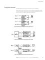
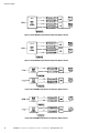
Configuration Schematics 45. . . . . . . . . . . . . . . . . . . . . . . . . . . . . . . . . . . . . . . . . . . . . . . . . . . . . . . . . . . . . .
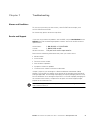
7 Troubleshooting 47. . . . . . . . . . . . . . . . . . . . . . . . . . . . . . . . . . . . . . . . . . . . . . . . . . . . .
Alarms and Conditions 47. . . . . . . . . . . . . . . . . . . . . . . . . . . . . . . . . . . . . . . . . . . . . . . . . . . . . . . . . . . . . . . .
Service and Support 47. . . . . . . . . . . . . . . . . . . . . . . . . . . . . . . . . . . . . . . . . . . . . . . . . . . . . . . . . . . . . . . . . .
8 Warranty 49. . . . . . . . . . . . . . . . . . . . . . . . . . . . . . . . . . . . . . . . . . . . . . . . . . . . . . . . . .

EATON Power Distribution Rack (208V) User’s Guide S 164201720 Rev 1 www.powerware.com
1
Chapter 1 Introduction
The Eaton
®
Power Distribution Rack (PDR), part of the Powerware
®
series, is designed
to provide increased distribution capacity in a standard data center enclosure that can
be placed anywhere within or at the end of the aisle, depending on configuration.
Providing outstanding performance and reliability, the PDR’s unique benefits include
the following:
S 208/120V, 50 Hz or 60 Hz three−phase power distribution unit, with one to four
panelboards, delivering up to 168 branch breakers
S Single−feed or dual−feed voltage sources (400A, 600A, 800A)
S Standard top and bottom cable entry in a free−standing structure
S Easy installation and servicing with front and rear access, spacious wireways, and
removable side panels, exterior doors, and interior barriers
S Conduit entry plates with plugged holes instead of knockouts
S Display viewable through the front exterior door for ease of use
S Lockable exterior doors and secure interior barriers accessible only by tool
S Firmware that is field upgradeable
S Separate isolated neutral busbar for each panelboard to connect the output cable
neutral conductor, in addition to a separate ground busbar that may be configured
for an isolated ground system
S Energy Management System (EMS) monitoring with single or dual displays.
EMS provides two levels of configuration and metering: System Level Monitoring
and Branch Circuit Monitoring System (BCMS). With BCMS, you can see the
current values of each of the distribution branch breakers, letting you measure,
plan, and manage power with greater precision.
EMS also provides communication options such as network connectivity. The
Power Xpert
®
Gateway Card installed in the X−Slot
®
communication bay provides
remote monitoring through a Web browser interface, e−mail, and a network
managment system using SNMP; connects to a twisted−pair Ethernet
(10/100BaseT) network. Modbus
®
TCP support provides direct integration of the
PDR’s parameters to a Building Management System (BMS). It has a built−in
switching hub that allows one additional network device to be connected to the
network without the requirement of an additional network drop.
NOTE LAN drops for use with the X−Slot card must be provided by the customer.

INTRODUCTION
EATON Power Distribution Rack (208V) User’s Guide S 164201720 Rev 1 www.powerware.com
2
The following options for the PDR are available:
S Choice of input connection:
Configuration Input Connection Aisle Location
Quad−Feed Input Direct connection to each panelboard breaker for one−, two−, three−, or four−input feed Anywhere in aisle
Single 800A Main Input Lug Connection into a main lug (up to 800A) mounted behind panelboard Anywhere in aisle
Dual 800A Main Input Lug Connection into dual main lugs (up to 800A) mounted behind panelboards on front and rear Anywhere in aisle
Single 400A Main Input Breaker Connection to a single 400A main breaker mounted on the side of the cabinet End of aisle only
Dual 400A Main Input Breaker Connection to dual 400A main breakers mounted on the side of the cabinet End of aisle only
Single 600A Main Input Breaker Connection to a single 600A main breaker mounted on the side of the cabinet End of aisle only
Dual 600A Main Input Breaker Connection to dual 600A main breakers mounted on the side of the cabinet End of aisle only
S Three−phase panelboard options for front and/or rear:
NOTE For a single−feed input, the minimum PDR configuration is one panelboard on the front.
Model
Number of
Panelboards
per Side
Type of Panelboard Number of Poles Capacity
Panelboard Breaker Rating
(Overall Short Circuit Rating)
PDR
1 or 2 Cutler−Hammer
®
column 42 320A 320A (10 kA)
1 or 2 Cutler−Hammer column 42 225A 225A (10 kA)
S Single 800A Main Input Lug, Dual 800A Main Input Lug, Single 400A Main Input Breaker,
Dual 400A Main Input Breaker, Single 600A Main Input Breaker, and Dual 600A Main Input
Breaker configurations. Choice of calculated or measured neutral current
S Branch circuit breakers installed at the factory
S Surge protection with Transient Voltage Surge Suppression / Surge Protective
Device (TVSS/SPD)
S Environmental Monitoring Probe (EMP) for monitoring ambient temperature and
humidity. The EMP also provides contact states for two additional devices that are
plugged into the EMP.
S Front exterior door options:
− Perforated door
− Glass door
− Perforated door with a cutout for the display
NOTE The rear door is a perforated split door.

INTRODUCTION
EATON Power Distribution Rack (208V) User’s Guide S 164201720 Rev 1 www.powerware.com
3
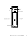
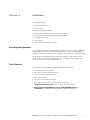
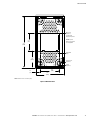
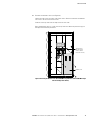
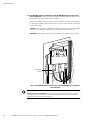
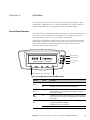
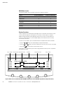
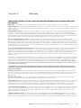
Figure 1 shows a PDR.
Display
Branch Circuit Breaker
View Slot (2 places)
TVSS/SPD Indicator
(2 places)
X−Slot Communication Bay
Panelboard Breaker
(2 places)
Tool Access Slot
(2 per interior barrier)
Panel Names (viewed from front):
Panelboard1F (front) Panelboard2F (front)
Panelboard1R (rear) Panelboard2R (rear)
Figure 1. PDR (Exterior Door Not Shown)

INTRODUCTION
EATON Power Distribution Rack (208V) User’s Guide S 164201720 Rev 1 www.powerware.com
4

EATON Power Distribution Rack (208V) User’s Guide S 164201720 Rev 1 www.powerware.com
5
Chapter 2 Safety Warnings
IMPORTANT SAFETY INSTRUCTIONS
SAVE THESE INSTRUCTIONS
S This manual contains important instructions that should be followed during installation and maintenance
of the Power Distribution Rack (PDR). Please read all instructions before operating the equipment and
save this manual for future reference.
S The PDR is designed for industrial or computer room applications, and contains safety shields (interior
barriers) behind the doors. The PDR system is a sophisticated power system and should be handled with
appropriate care.
D A N G E R
The PDR contains LETHAL VOLTAGES. All repairs and service should be performed by AUTHORIZED
SERVICE PERSONNEL ONLY. There are NO USER SERVICEABLE PARTS inside the PDR.
W A R N I N G
S To reduce the risk of fire or electric shock, install this PDR in a temperature and humidity controlled,
indoor environment, free of conductive contaminants. Ambient temperature must not exceed 40°C
(104°F). Do not operate near water or excessive humidity (95% maximum). The system is not intended for
outdoor use.
S Ensure all power is disconnected before performing installation or service.
C A U T I O N
S Keep the PDR doors closed to ensure proper cooling airflow and to protect personnel from dangerous
voltages inside the unit.
S Do not operate the PDR close to gas or electric heat sources.
S Locate the PDR on a concrete or other non−combustible surface only.
S The operating environment should be maintained within the parameters stated in this manual.
S Keep surroundings uncluttered, clean, and free from excess moisture.
S Use leveling feet only for distributing the weight of the cabinet equally. Using the leveling feet to raise
the cabinet may result in serious injury to personnel or damage to the cabinet.
S Observe all DANGER, CAUTION, and WARNING notices affixed to the inside and outside of the
equipment.

SAFETY WARNINGS
EATON Power Distribution Rack (208V) User’s Guide S 164201720 Rev 1 www.powerware.com
6

EATON Power Distribution Rack (208V) User’s Guide S 164201720 Rev 1 www.powerware.com
7
Chapter 3 Installation
This section explains:
S Equipment inspection
S Tools required
S Planning the cabinet location
S Unpacking the cabinet and checking the accessory kit
S Preparing and moving the cabinet to its final location
S Installation and wiring
S Initial startup
S Completing the installation checklist
Inspecting the Equipment
If any equipment has been damaged during shipment, keep the shipping cartons and
packing materials for the carrier or place of purchase and file a claim for shipping
damage. If you discover damage after acceptance, file a claim for concealed damage.
To file a claim for shipping damage or concealed damage: 1) File with the carrier
within 15 days of receipt of the equipment; 2) Send a copy of the damage claim
within 15 days to your service representative.
Tools Required
To assemble the components, the following tools may be needed:
S #1 and #2 slotted screwdrivers
S M10, M13, and 5/16" socket wrenches
S 14 mm socket and socket wrench
S 5/16" Allen wrench
S 3/4" and 1−1/8" open−end wrenches
S Step ladder, for ease of access to the top of the cabinet
S Configurations with side breakers. 10 mm socket and socket wrench
S Quad−Feed Input, Single 800A Main Input Lug, and Dual 800A Main Input Lug
configurations. Crimping tools recommended in Table 2 on page 19.

INSTALLATION
EATON Power Distribution Rack (208V) User’s Guide S 164201720 Rev 1 www.powerware.com
8
Planning the Cabinet Location
Follow these guidelines for planning the cabinet’s final location:
S Place the cabinet on a concrete or other non−combustible surface in a protected
area that has adequate airflow and is free of humidity, flammable gas, and
corrosion.
S DO NOT place the cabinet on its side.
To plan the cabinet’s location:
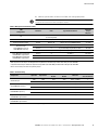
1. Verify that the final location for the cabinet has the following clearances. Check
your local codes and regulations for other recommended clearances.
Table 1. Cabinet Clearances
Cabinet Area Clearance
Above A minimum of 460 mm (18") for the exit of cables and conduit and for ventilation
Below A minimum of 150 mm (6") for the exit of cables and conduit and for ventilation
NOTE This clearance can be provided by a raised floor.
Front (single door) 910 mm (36") for access
Rear (double doors) Configurations with rear panelboards installed. 910 mm (36") for access
Configurations without rear panelboards installed. 455 mm (18") for access
Sides Configurations with side breakers. End of aisle installation only
Configurations without side breakers. None required
NOTE 38 mm (1.5") allows the doors to open past 90° for easier access to front
and rear breakers.
2. Verify that the cabinet does not exceed your floor loading capacity. See Table 9
on page 43 for cabinet weight and dimensions.
3. Verify that the location meets the environmental requirements listed in Table 13
on page 44.
4. Plan the cable routing and conduit access to the cabinet:
S The top and bottom of the cabinet have swappable entry plates and
removable plugs for cable connection. See Figure 2 on page 11.
S Identify all conduit requirements and mark their location.
S To avoid congestion and allow for future load increases, use the conduit
openings closest to the center of the cabinet first.
S Bottom entry wiring. To allow for proper bending radius and ease of installation,
for ground and neutral connections use the conduit openings farthest from the
connection.
S Size conduit to accommodate one neutral conductor the same size as the
phase conductor and one ground conductor. If two neutral conductors or an
oversized neutral conductor are to be installed, size the conduit to
accommodate the extra wire or size. All PDR products can accommodate a
double−sized neutral.

INSTALLATION
EATON Power Distribution Rack (208V) User’s Guide S 164201720 Rev 1 www.powerware.com
9
Unpacking the Cabinet
C
A U T I O N
S Only qualified personnel should be permitted to perform any work associated with this equipment.
S Unpacking the cabinet in a low−temperature environment may cause condensation to occur in and on the
cabinet. Do not install the cabinet until the inside and outside of the cabinet are absolutely dry (risk of
electric shock).
S The cabinet is heavy (see page 43). Removing the cabinet from its packaging requires a minimum of three
people.
S Do not install a damaged cabinet. Report any damage to the carrier and contact your service
representative immediately.
Do not remove protective packaging until the equipment is ready for installation.
To unpack the cabinet:
1. Carefully inspect the outer packaging for evidence of damage during transit.
2. Move the packaged cabinet as near as possible to its final location.
3. Remove the outer layer of shrinkwrap.
4. Remove the ramp packaged next to the cabinet and retain for later use to roll the
cabinet off the pallet.
5. Remove the inner layer of shrinkwrap and the large cardboard corner posts.
6. Remove the large plastic bag covering the cabinet.
7. Remove the accessory kit box from beside the cabinet.
C A U T I O N
S The cabinet may roll when resting on its casters. Take proper care to secure the cabinet and ensure the
safety of personnel.
S Do not stand on or in the cabinet. The cabinet may tip and cause serious injury. Do not work on or in the
cabinet until the leveling feet are in place.
8. The cabinet is bolted to the pallet in four places with heavy−duty anchoring feet.
Using care to verify that the cabinet does not roll on its casters, use a 14 mm
socket and socket wrench to remove the anchoring hardware.
9. Verify that the installed leveling feet are retracted sufficiently to allow the cabinet
to move easily.
10. Place the supplied ramp next to the pallet, inserting the two hooks on the top of
the ramp into the holes near the top edge of the pallet. Verify the ramp is firmly
and securely seated.
11. Carefully roll the cabinet off the pallet. Use three people to ensure the cabinet
does not tip.
12. Discard or recycle the pallet and packaging in a responsible manner, or store
them for future use.

INSTALLATION
EATON Power Distribution Rack (208V) User’s Guide S 164201720 Rev 1 www.powerware.com
10
Checking the Accessory Kit
Verify that the following items are included inside the accessory kit box:
S This user’s guide
S (2) Door keys
S Breaker handle
S Arc flash hazard label
S Configurations with side breakers. (10) Panel keys
Quad−Feed Input, Single 800A Main Input Lug, and Dual 800A Main Input Lug configurations.
Verify that a separate package of the following items is included with the cabinet:
S One side. (12) Ring terminal lugs and nuts
S Two sides. (24) Ring terminal lugs and nuts
Preparing the Cabinet
To prepare the cabinet for installation:
1. Verify operation of the door handles:
To open a door, push in on the key lock. The handle pops up. Pull out on the
handle.
To close a door, push in on the handle until it snaps into place.
2. Verify that the supplied keys lock and unlock the doors.
3. Place the breaker handle on one of the breakers.
Use the breaker handle to open and close the breakers during operation of the
PDR. Remove the breaker handle as needed to open and close the exterior doors
or interior barriers.
4. Place the supplied arc flash hazard label in a location obvious to the user.
Moving the Cabinet to its Final Location
NOTE If installing the cabinet over a raised floor, roll the cabinet over two sheets of 3/4" thick plywood to
evenly distribute the weight and protect the floor. Use care when positioning the cabinet to avoid the casters
falling through the cutouts in the raised floor.
1. Verify that all steps in Planning the Cabinet Location" on page 8 have been
performed.
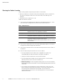
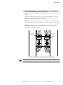
2. Bottom entry wiring. Install a cutout in the floor as needed, using the template
shown in Figure 2.
3. Remove the top entry plate or the bottom entry plate, depending on installation.
4. Roll the cabinet to its final position. For bottom entry wiring, carefully position the
cabinet over the cutout in the floor.
5. Use a 1−1/8" open−end wrench to lower each leveling foot until it makes firm
contact with the floor. Verify that the cabinet is level. Tighten each leveling foot
using a 3/4" open−end wrench. The cabinet is now stable and in place.

INSTALLATION
EATON Power Distribution Rack (208V) User’s Guide S 164201720 Rev 1 www.powerware.com
11
Leveling Foot
(4 places)
Caster
(4 places)
14.2
[361]
41.3
[1050]
13.6
[344.5]
3.8
[97]
16.0
[406]
23.6
[600]
NOTE Dimensions are in inches [mm].
M5 Screw
(4 places)
for Removing
Bottom Entry Plate
NOTE Top and
bottom entry plates
are swappable.
Removable
Plugs
Figure 2. PDR Bottom View

INSTALLATION
EATON Power Distribution Rack (208V) User’s Guide S 164201720 Rev 1 www.powerware.com
12
Installing the PDR
This section explains wiring installation for the PDR.
The PDR has side panels, exterior doors, and interior barriers that protect the
panelboards, breakers, and interior wiring. The panels, doors, and barriers can be
removed for ease of installation and maintenance.
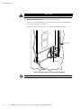
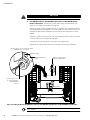
Removing the Solid Side Panel
NOTE Follow this procedure for installations with side access only. For configurations without side
breakers, remove either or both solid side panels to gain side access. To remove a side panel with breakers,
see the following section, Removing the Side Panel with Breakers."
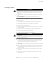
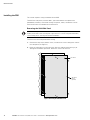
To remove the solid side panel before wiring:
1. Remove the top screw, bottom screw, and the three screws along each side of
the side panel (see Figure 3).
2. Place the side panel in a safe area away from the cabinet to prevent injury or
damage to the PDR or personnel. Retain the screws for later use.
Side Panel
Side Panel
Screw
(8 places)
Figure 3. Removing the Solid Side Panel

INSTALLATION
EATON Power Distribution Rack (208V) User’s Guide S 164201720 Rev 1 www.powerware.com
13
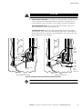
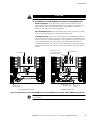
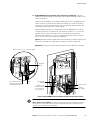
Removing the Side Panel with Breakers
NOTE Follow this procedure for configurations with side breakers.
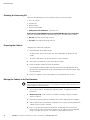
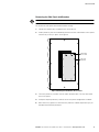
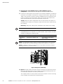
To remove the side panel with breakers before wiring:
1. Locate the 10 panel keys supplied in the accessory kit.
2. Slide a panel key into each horizontal panel lock on the side breaker access panel
until the key is firmly in place. See Figure 4.
Panel Lock
(10 places)
Side Breaker
Access Panel
Figure 4. Removing the Side Breaker Access Panel
3. Turn each panel key a quarter turn to unlock the panel lock. The key locks onto
the access panel.
4. Grasp the top two panel keys and lift the access panel straight off the cabinet.
5. Place the access panel in a safe area away from the cabinet to prevent injury or
damage to the PDR or personnel.

INSTALLATION
EATON Power Distribution Rack (208V) User’s Guide S 164201720 Rev 1 www.powerware.com
14
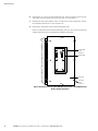
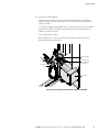
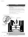
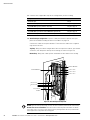
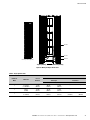
6. Remove the six screws inside the breaker well. There are three screws on each
side within the well. Retain the screws for later use. See Figure 5.
7. Remove the top screw, bottom screw, and the three screws along each side of
the side panel. Retain the screws for later use.
8. Remove the side panel with the attached breaker well.
Place the side panel with the attached breaker well in a safe area away from the
cabinet to prevent injury or damage to the PDR or personnel.
Side Panel
Screw
(8 places)
Side Panel
Breaker Well
Screw
(6 places)
Breaker Well
Figure 5. Removing the Side Panel (Dual 400A Main Input Breaker or Dual 600A Main Input
Breaker Configuration Shown)
Page is loading ...
Page is loading ...
Page is loading ...
Page is loading ...
Page is loading ...
Page is loading ...
Page is loading ...
Page is loading ...
Page is loading ...
Page is loading ...
Page is loading ...
Page is loading ...
Page is loading ...
Page is loading ...
Page is loading ...
Page is loading ...
Page is loading ...
Page is loading ...
Page is loading ...
Page is loading ...
Page is loading ...
Page is loading ...
Page is loading ...
Page is loading ...
Page is loading ...
Page is loading ...
Page is loading ...
Page is loading ...
Page is loading ...
Page is loading ...
Page is loading ...
Page is loading ...
Page is loading ...
Page is loading ...
Page is loading ...
Page is loading ...
Page is loading ...
Page is loading ...
-
 1
1
-
 2
2
-
 3
3
-
 4
4
-
 5
5
-
 6
6
-
 7
7
-
 8
8
-
 9
9
-
 10
10
-
 11
11
-
 12
12
-
 13
13
-
 14
14
-
 15
15
-
 16
16
-
 17
17
-
 18
18
-
 19
19
-
 20
20
-
 21
21
-
 22
22
-
 23
23
-
 24
24
-
 25
25
-
 26
26
-
 27
27
-
 28
28
-
 29
29
-
 30
30
-
 31
31
-
 32
32
-
 33
33
-
 34
34
-
 35
35
-
 36
36
-
 37
37
-
 38
38
-
 39
39
-
 40
40
-
 41
41
-
 42
42
-
 43
43
-
 44
44
-
 45
45
-
 46
46
-
 47
47
-
 48
48
-
 49
49
-
 50
50
-
 51
51
-
 52
52
-
 53
53
-
 54
54
-
 55
55
-
 56
56
-
 57
57
-
 58
58


Eaton Power Distribution Rack 208V User manual
- Type
- User manual
- This manual is also suitable for
Ask a question and I''ll find the answer in the document
Finding information in a document is now easier with AI
Related papers
-
Eaton 164201420B User manual
-
Eaton CHSPT2SURGE Specification
-
Eaton IM01005012E User manual
-
-
-
-
-
Eaton EMA014 Specification
-
-
Eaton 415/240V User manual
Other documents
-
Hager VME01SPD Protection Devices Surge Protection Kit User manual
-
Legrand ZoneMaster Series Hard-Wired Surge Protection Remote Monitor - ZHRMU Installation guide
-
 PROGRESSIVE INDUSTRIES EMS-HW50C Operating instructions
-
Compaq 252663-B24 - PDU Power Distribution Strip Introduction Manual
-
Square D QOM2100MM User manual
-
-
Cooper Lighting TracKeeper Current Limiting Panel Installation guide
-
 PROGRESSIVE INDUSTRIES HW30C User manual
-
 Thermo Fisher Scientific pDR1000an User manual
-
Toshiba TVS-XT140-120 User manual


