Kozyheat Slayton 42S Owner's manual
- Category
- Fireplaces
- Type
- Owner's manual

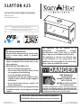
SLAYTON 42S
INSTALLATION AND OPERATION MANUAL
Model #SLA-42S
Direct Vent Gas Fireplace
ͷDo not store or use gasoline or other ammable
vapors and liquids in the vicinity of this or any
other appliance.
ͷWHAT TO DO IF YOU SMELL GAS
• Do not try to light any appliance.
•Do not touch any electrical switch; do not
use any phone in your building.
• Leave the building immediately.
•Immediately call your gas supplier from a
neighbor’s phone. Follow the gas supplier’s
instructions.
•If you cannot reach your gas supplier, call
the re department.
ͷInstallation and service must be performed by
a qualied installer, service agency or the gas
supplier.
WARNING:
FIRE OR EXPLOSION HAZARD
Failure to follow safety warnings exactly could
result in serious injury, death, or property
damage.
This appliance may be installed in an
aermarket, permanently located,
manufactured home (USA only) or mobile
home, where not prohibited by local codes.
This appliance is only for use with the type
of gas indicated on the rang plate. This
appliance is not converble for use with other
gases, unless a cered kit is used.
INSTALLER: Leave this manual with the appliance.
CONSUMER: Retain this manual for future reference.
English and French installation manuals are available through your local
dealer. Visit our website www.kozyheat.com.
Les manuels d’installation en français et en anglais sont disponibles chez
votre détaillant local. Visitez www.kozyheat.com.
DANGER
HOT GLASS WILL
CAUSE BURNS
DO NOT TOUCH GLASS
UNTIL COOLED
NEVER ALLOW CHILDREN
TO TOUCH GLASS
A barrier designed to reduce the risk of burns
from the hot viewing glass is provided with this
appliance and shall be installed for the protection
of children and other at-risk individuals.
Hussong Mfg. Co., Inc.
SLA-42S Report No: 19-505
Rev. 11, September 2023
Starting Serial Number: 22 068529 12


Read this manual before installation or operating this appliance. Please retain this owner’s manual for future reference.
CONGRATULATIONS!
We welcome you as a new owner of a Kozy Heat gas replace. Kozy Heat products are designed
with superior components and materials, and assembled by trained craftsmen who take pride in
their work. To ensure you receive a quality product, the burner and valve assembly are 100 percent
test-red, and the complete replace is thoroughly inspected before packaging. Our commitment to
quality and customer satisfaction has remained the same for over 40 years. We offer a complete line of
gas, wood, and electric replaces, along with stylish accessories to complement any decor. Adding
a replace is one of the best ways to increase the value of your home, and we are proud to offer a
network of dealers throughout the country to help make your experience everything you imagine. We
pride ourselves in being dedicated not only to functionality and reliability, but also customer safety.
We offer our continual support and guidance to help you achieve the maximum benet and
enjoyment from your Kozy Heat gas replace.
Jim Hussong
President
Dudley Hussong
Board Chairman
Homeowner Reference Information
We recommend you record the following information:
Model Name: ____________________________________________
Serial Number: ___________________________________________
Dealership Purchased from: ________________________________
Date purchased/installed: __________________________________
Location of replace: ______________________________________
Dealer phone: ___________________________________________
Notes: ______________________________________________________________________________________________________________
____________________________________________________________________________________________________________________
____________________________________________________________________________________________________________________
____________________________________________________________________________________________________________________
#SLA-42S
Rev. 11, September 2023
3
HUSSONG MFG. CO., INC. KOZY HEAT FIREPLACES


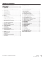
TABLE OF CONTENTS
HOMEOWNER REFERENCE INFORMATION .................................3
TABLE OF CONTENTS ..................................................................... 5
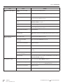
1.0 INTRODUCTION ......................................................................7
1.1 Appliance Certication ............................................................................ 7
1.2 California Proposition 65 Warning ....................................................... 7
1.3 Requirements for the Commonwealth of Massachusetts ........... 7
2.0 SPECIFICATIONS ..................................................................... 8
2.1 Heating Specications.............................................................................. 8
2.2 Electrical Specications ........................................................................... 8
2.3 Appliance Dimensions ............................................................................. 9
2.4 Safety Barrier Dimensions ....................................................................... 10
3.0 FRAMING .................................................................................11
3.1 Installation Planning ................................................................................. 11
3.2 Stand-o Assembly and Installation ................................................... 12
3.3 Nailing Flange Assembly and Installation ......................................... 13
3.4 Clearances to Combustibles ................................................................... 14
3.5 Rough Framing ...........................................................................................15
3.6 Outdoor Covered Fireplace Installation ............................................. 18
4.0 FACING AND FINISHING .........................................................20
4.1 Facing and Finishing Requirements ................................................... 20
4.2 Safety Barrier Installation ........................................................................ 24
4.3 Optional Trim Kit Assembly #SL42-FTK .............................................. 25
5.0 GAS LINE CONNECTION .........................................................26
5.1 Gas Conversion ...........................................................................................26
5.2 Gas Line Installation .................................................................................. 26
6.0 TERMINATION LOCATIONS ....................................................27
6.1 Vertical Vent Termination ........................................................................ 27
6.2 Minimum Vent Termination Clearances ............................................. 28
7.0 VENTING ..................................................................................29
7.1 Approved Vent Systems ........................................................................... 29
7.2 Venting Requirements .............................................................................. 29
7.3 Vent Restriction ........................................................................................... 30
7.4 Vent Heat Shield Assembly Installation.............................................. 31
7.5 Vent Installation .......................................................................................... 32
7.6 #800-1 Series Direct Vent Termination Kit(s) .................................... 37
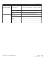
8.0 FIREPLACE SET UP ..................................................................38
8.1 Glass Frame Assembly .............................................................................. 38
8.2 Light Kit .......................................................................................................... 38
8.3 Glass Media .................................................................................................. 39
8.4 Control Board Removal and Installation ............................................ 40
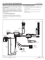
9.0 ELECTRICAL INFORMATION .................................................. 41
9.1 Electrical Specications ........................................................................... 41
9.2 Wiring Requirements ................................................................................ 41
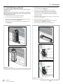
9.3 #SL42-028 Optional Fan Kit .................................................................... 42
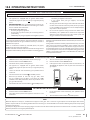
10.0 OPERATING INSTRUCTIONS ................................................ 43
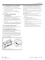
10.1 Setup Komfort 8K Control Module .................................................... 44
10.2 Initialize the Komfort 8K Control System ........................................ 44
10.3 Automatic Safety Turn-o .................................................................... 44
10.4 Backup Battery Operation .................................................................... 44
10.5 Control System 7 Day Time-out .......................................................... 44
10.6 Komfort 8K Control System Ignition Sequence ............................ 45
10.7 Additional Diagnostic Information ...................................................45
10.8 Remote Control Operation ................................................................... 46
11.0 ADJUSTMENT ........................................................................50
11.1 Pressure Testing ........................................................................................ 50
11.2 Flame Appearance Adjustment .......................................................... 51
12.0 TROUBLESHOOTING............................................................. 53
13.0 MAINTENANCE......................................................................56
13.1 Firebox ......................................................................................................... 56
13.2 Fan (optional) ............................................................................................ 56
13.3 Vent System ............................................................................................... 56
13.4 Glass Assembly ......................................................................................... 56
13.5 Burner and Pilot System ....................................................................... 57
14.0 REPLACEMENT PARTS LIST..................................................58
LIMITED LIFETIME WARRANTY ....................................................59
#SLA-42S
Rev. 11, September 2023
5
HUSSONG MFG. CO., INC. KOZY HEAT FIREPLACES


Appliance Certication–Requirements for Massachusetts
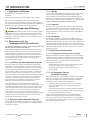
SECTION 1 INTRODUCTION
#SLA-42S#SLA-42S
Rev. 11, September 2023
7
HUSSONG MFG. CO., INC. KOZY HEAT FIREPLACES
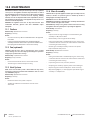
1.1 Appliance Certication
Laboratory: PFS in Cottage Grove, Wisconsin
Standards:
ANSI Z21.88-2017/CSA 2.33-2017, Vented Gas Fireplace Heaters
CSA 2.17 2017, Gas-Fired Appliances for Use at High Altitudes
This installation must conform with local codes, or in the absence of
local codes, with the National Fuel Gas Code, ANSI Z223.1/NFPA 54, or
the Natural Gas and Propane Installation Code, CSA B149.1.
1.2 California Proposition 65 Warning
WARNING: This product can expose you to chemicals including
Carbon Monoxide, that is an externally vented by-product of fuel
combustion, which is [are] known to the State of California to cause
birth defects or other reproductive harm. For more information, visit
www.P65Warnings.ca.gov.
1.3 Requirements for the
Commonwealth of Massachusetts
The following requirements reference various Massachusetts and
national codes not contained in this manual.
For all sidewall horizontally vented gas fueled equipment installed
in every dwelling, building or structure used in whole or in part for
residential purposes, including those owned or operated by the
Commonwealth and where the side wall exhaust vent termination
is less than (7) feet above nished grade in the area of the venting,
including but not limited to decks and porches, the following
requirements shall be satised:
1.3.1 Installation of Carbon Monoxide Detectors
At time of installation of side wall horizontally vented gas fueled
equipment, the installing plumber or gas-tter shall observe that
a hard wired carbon monoxide detector with an alarm and battery
back-up is installed on the oor level where the gas equipment is
to be installed. In addition, the installing plumber or gas-tter shall
observe that a battery operated or hard wired carbon monoxide
detector is installed on each additional level of the dwelling, building
or structure served by the side wall horizontal vented gas fueled
equipment. It shall be the responsibility of the property owner
to secure the services of qualied licensed professionals for the
installation of hard wired carbon monoxide detectors.
In the event that the side wall horizontally vented gas fueled
equipment is installed in a crawl space or attic, the hard wired carbon
monoxide detector with alarm and battery back-up may be installed
on the next adjacent oor level. In the event that the requirements
of this subdivision can not be met at the time of completion of
installation, the owner shall have a period of thirty (30) days to
comply with the above requirements; provided, however, that during
said thirty (30) day period, a battery operated carbon monoxide
detector with an alarm shall be installed.
1.3.2 Approved Carbon Monoxide Detectors
Each carbon monoxide detector as required in accordance with the
above provisions shall comply with NFPA 720 and be ANSI/UL 2034
listed and IAS certied.
1.3.3 Signage
A metal or plastic identication plate shall be permanently mounted
to the exterior of the building at a minimum of eight (8) feet
above grade directly in line with the exhaust vent terminal for the
horizontally vented gas fueled heating appliance or equipment. The
sign shall read, in print no less the one-half inch (½) in size, “GAS VENT
DIRECTLY BELOW. KEEP CLEAR OF ALL OBSTRUCTIONS”.
1.3.4 Inspection
The state or local gas inspector of the side wall horizontally vented
gas fueled equipment shall not approve the installation unless, upon
inspection, the inspector observes carbon monoxide detectors and
signage installed in accordance with the provisions of 248 CMR 5.08
(2) (a) 1 through 4.
1.3.5 Exemptions
The following equipment is exempt from 248 CMR 5.08 (2) (a) 1
through 4: The equipment listed in Chapter 10 entitled “Equipment
Not Required To Be Vented” in the most current edition of NFPA 54 as
adopted by the Board; and Product Approved side wall horizontally
vented gas fueled equipment installed in a room or structure separate
from the dwelling, building or structure used in whole or in part for
residential purposes.
1.3.6 Manufacturer Requirements
1.3.6.1 Gas Equipment Venting System Provided
When the manufacturer of Product Approved side wall horizontally
vented gas equipment provides a venting system design or venting
system components with the equipment, the instructions provided
by the manufacturer for installation of the equipment and the
venting system shall include:
• Detailed instructions for the installation of the venting system
design or the venting system components; and
• A complete parts list for the venting system design or
venting system.
1.3.7 Gas Equipment Venting
System NOT Provided
When the manufacturer of Product Approved side wall horizontally
vented gas equipment does not provide the parts for venting the
ue gases, but identies “special venting systems”, the following
requirements shall be satised by the manufacturer:
• The referenced “special venting systems” instructions shall
be included with the appliance or equipment installation
instructions and;
• The “special venting systems” shall be Product Approved by the
Board, and the instructions for that system shall include a parts
list and detailed installation instructions.
A copy of all installation instructions for all Product Approved
side wall horizontally vented gas fueled equipment, all venting
instructions, all parts lists for venting instructions, and/or all venting
design instructions shall remain with the appliance or equipment at
the completion of the installation.
1.0 INTRODUCTION

Heating Specications
SECTION 2 SPECIFICATIONS
#SLA-42S
Rev. 11, September 2023
8HUSSONG MFG. CO., INC. KOZY HEAT FIREPLACES
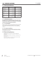
2.0 SPECIFICATIONS
2.1 Heating Specications
Natural Gas Propane
Maximum
Input Rating
42,000 Btu/h
(12.3 kW)
42,000 Btu/h
(12.3 kW)
Minimum
Input Rating
21,000 Btu/h
(6.154 kW)
21,000 Btu/h
(6.154 kW)
Manifold Pressure
(High)
3.5” WC
(0.87 kPa)
10” WC
(2.49 kPa)
Manifold Pressure
(Low)
1” WC
(0.24 kPa)
2.7” WC
(0.67 kPa)
Orice Size
(DMS)
CENTER BURNER: 37
SIDE BURNERS: 54
CENTER BURNER: 52
SIDE BURNERS: 67
2.1.1 Altitude Adjustment
This appliance may be installed at higher altitudes. Please refer to
National Fuel Gas Code ANSI Z223.1/NFPA 54, CSA-B149.1 Natural
Gas and Propane Installation Code, local authorities, or codes having
jurisdiction in you area regarding derate guidelines.
2.1.1.1 US Installations
Refer to the American Gas Association guidelines for the gas designed
appliances derating method. For elevations above 2,000’ (610m),
input ratings are to be reduced by 4% for each 1,000’ (305m) above
sea level.
2.1.1.2 Canadian Installations
When the appliance is installed at elevations above 4,500’ (1,372m),
the certied high altitude rating shall be reduced at the rate of 4% for
each additional 1,000’ (305m).
2.2 Electrical Specications
• The junction box in this appliance requires 120VAC, 60Hz,
and 6 Amps.
• Verify the household breaker is shut o prior to working on any
electrical lines.
• The AC power supply to this appliance must be hot at all times
and shall not have a switch installed in it.

Appliance Dimensions
SECTION 2 SPECIFICATIONS
#SLA-42S
Rev. 11, September 2023
9
HUSSONG MFG. CO., INC. KOZY HEAT FIREPLACES
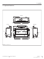
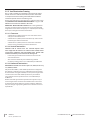
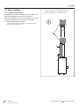
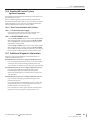
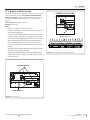
2.3 Appliance Dimensions
19”
(483mm)
3/8”
(10mm)
9⁄”
(252mm) 15⁄”
(402mm)
55¼”
(1404mm)
5¾”
(146mm) 10⁄”
(272mm)
19⁄”
(494mm)
45⁄”
(1154mm)
8⁄”
(206mm)
50”
(1271mm)
55¼”
(1404mm)
32⁄”
(827mm)
38⁄”
(972mm)
10⁄”
(256mm)
5¼”
(133mm)
2¼”
(57mm)
9⁄”
(246mm)
5¼”
(133mm)
TOP VIEW
FRONT VIEWLEFT SIDE RIGHT SIDE
Finishing edge
Electrical access
Gas line hole
Gas line hole
FIGURE 2.1 SLA-42S Dimensions

Safety Barrier Dimensions
SECTION 2 SPECIFICATIONS
#SLA-42S
Rev. 11, September 2023
10 HUSSONG MFG. CO., INC. KOZY HEAT FIREPLACES
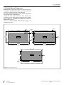
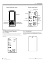
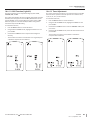
2.4 Safety Barrier Dimensions
WARNING: A barrier designed to reduce the risk of burns from the hot
viewing glass is provided with this appliance and shall be installed for
the protection of children and other at-risk individuals.
If the barrier becomes damaged, the barrier shall be replaced with
Hussong Mfg.’s barriers for this appliance.
Consider the nish material dimensions when planning your
installation. The safety barrier and glass assembly must be removable.
Refer to FIGURE 4.3, MINIMUM NONCOMBUSTIBLE MATERIAL
DIMENSIONS on page 23.
Refer to 4.2, SAFETY BARRIER INSTALLATION on page 24 for
installation instructions.
3⁄”
(86mm)
26⁄”
(665mm)
51⁄”
(1316mm)
3⁄”
(82mm)
26¼”
(667mm)
3⁄”
(87mm)
52⁄”
(1325mm)
21⁄”
(543mm) ⁄”
(24mm)
47¼”
(1200mm)
3⁄”
(87mm)
SL42-CXSFS SL42-BSFS
SL42-RSFS
FINISHING
EDGE
FINISHING
EDGE
FIGURE 2.2 Safety Barrier Dimensions

Installation Planning
SECTION 3 FRAMING
#SLA-42S
Rev. 11, September 2023
11
HUSSONG MFG. CO., INC. KOZY HEAT FIREPLACES
3.0 FRAMING
3.1 Installation Planning
• If planning to convert to propane, it is easier to complete the gas
conversion before framing in the replace. See the #LCK-SL42-D
manual for complete conversion instructions. If you convert the
replace to propane after replace installation, you will have to
remove the control board. See section 8.4, CONTROL BOARD
REMOVAL AND INSTALLATION (page 40) for access to the
control board before and after installation.
3.1.1 Appliance Placement Considerations
WARNING: Due to high temperatures, the appliance should be located
out of trac and away from furniture and draperies.
• This appliance must be installed on a level surface capable of
supporting the replace and venting.
• This replace may be installed in a bedroom.
• Please be aware of the large amount of heat this replace will
produce when determining a location.

Stand-o Assembly and Installation
SECTION 3 FRAMING
#SLA-42S
Rev. 11, September 2023
12 HUSSONG MFG. CO., INC. KOZY HEAT FIREPLACES
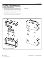
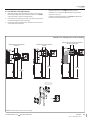
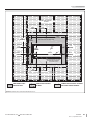
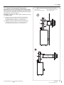
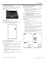
3.2 Stand-o Assembly and Installation
Top stand-o brackets must be formed and attached prior to
positioning replace into framed opening.
1. Remove and save the (4) screws securing the secondary stand-
o heat shield and the top stand-o brackets, located on the top
of the replace.
2. Form the top stand-o brackets as shown, then re-attach to the
replace using screws previously removed, along with (4) screws
provided in the replace components packet.
3. Form secondary heat shield and attach to top stand-o brackets
using (4) screws provided in the replace component packet.
4. Form the top stand-o upper heat shield as shown, and attach
to top stand-o brackets with the (4) screws provided in the
replace component packet.
5. Form back stand-os and secure to replace back with
provided screws.
FIGURE 3.1 Stand-o Assembly and Installation

Nailing Flange Assembly and Installation
SECTION 3 FRAMING
#SLA-42S
Rev. 11, September 2023
13
HUSSONG MFG. CO., INC. KOZY HEAT FIREPLACES
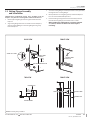
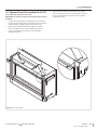
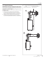
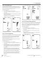
3.3 Nailing Flange Assembly
and Installation
CAUTION: Never permanently remove these assemblies from the
replace—they must be secured regardless of nish material used.
1. Remove (4) nailing anges from the right and left side of the
replace.
2. Align nailing ange with holes on outside corners of replace,
with the stand-o anges on the nailing anges facing away
from the replace
3. Secure the nailing anges to the replace with screws (provided)
through the slots in nailing anges.
4. Bend perforation on nailing ange until parallel with replace
face. Do not bend toward replace face.
5. Position framing stud against the small stand-o (located on
backside of nailing ange). Secure with nails or screws.
• When installed, the nailing anges provide the minimum
2½” (64mm) clearance from the sides of the replace
to framing.
STAND-OFF FLANGE
NAILING FLANGE
AS SHIPPED
NAILING FLANGE INSTALLED
NAILING FLANGE
INSTALLED
FRAMING STUD
NAILING FLANGE
STAND-OFF FLANGE
FRAMING STUD
NAILING FLANGE
2½”
(64mm)
CLEARANCE
BACK VIEW FRONT VIEW
TOP VIEW FRONT VIEW
FIGURE 3.2 Nailing Flange Installation

Clearances to Combustibles
SECTION 3 FRAMING
#SLA-42S
Rev. 11, September 2023
14 HUSSONG MFG. CO., INC. KOZY HEAT FIREPLACES
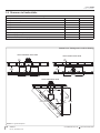
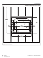
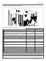
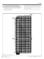
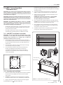
3.4 Clearances to Combustibles
Table 3.1, Minimum Appliance Clearances to Combustible Material
From appliance top stand-os 0” 0mm
From appliance left and right side stand-os 0” 0mm
From appliance back stand-os 0” 0mm
From appliance bottom stand-os 0” 0mm
From appliance corners 4” 102mm
From appliance front 36” 914mm
Top of nishing edge to ceiling 36” 914mm
Sides of nishing edge to adjacent sidewall 6” 152mm
Mantel 9” (229mm) deep from nishing edge 14-1/4” 362mm
3⁄”
(80mm)
19”
(483mm)
55¼”
(1403mm)
26⁄”
(670mm)
92⁄”
(2358mm)
½”
(13mm)
4”
(102mm)
65⁄”
(1667mm)
46⁄”
(1178mm)
3⁄”
(80mm)
19”
(483mm)
55¼”
(1403mm)
55¼”
(1403mm)
TYPICAL HORIZONTAL INSTALLATION TYPICAL VERTICAL INSTALLATION
TYPICAL CORNER INSTALLATION
FIGURE 3.3 Typical Install Options
Nominal 2“ x 4” framing used in enclosure framing

Rough Framing
SECTION 3 FRAMING
#SLA-42S
Rev. 11, September 2023
15
HUSSONG MFG. CO., INC. KOZY HEAT FIREPLACES
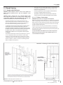
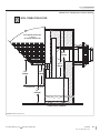
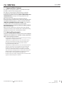
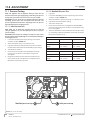
3.5 Rough Framing
3.5.1 Rough-in Wall Enclosure
WARNING: Provide adequate clearance in front of the replace for
barrier removal, component access, gas line installation, service
access, etc.
CAUTION: Cold air transfer area. The surround replace chase
must comply with all clearances as outlined in this manual, and be
constructed in compliance with local building codes. Outside walls
should be insulated to prevent cold air from entering room.
• Determine if the fireplace face will be flush with the wall
surface (where the wall surface and fireplace will be covered
with non-combustible material, such as tile) or the fireplace
face will be flush with framing (flat wall appearance).
•19” (483mm) represents the minimum distance from the front
of the fireplace to the back wall of the framing. This is the
minimum wall depth required for wall surface material to cover
the fireplace front. If you desire the wall surface to be flush with
the fireplace face, subtract 1/2” (25mm) (standard drywall
depth) from this dimension. If using another material, adjust
accordingly.
• The bottom of the fireplace must be placed directly on a wood
or non-combustible surface (not linoleum or carpet). If this
appliance is to be installed directly on carpeting, tile, or other
combustible material other than wood flooring, this appliance
shall be installed on a metal or wood panel extending the full
width and depth of the appliance.
• This fireplace may be elevated off the floor as shown below,
provided it is properly supported by framing materials and
maintains ceiling clearances.
•If masonry (optional) is to be used, prepare the foundation
necessary to support the full masonry load.
•The header is required to be a vertical header to maintain
clearances. Pictures are shown with double vertical header.
3.5.1.1 TV Recess Construction
WARNING: All clearances to venting must be maintained.
Mounting a television above a replace is a common practice. Mantel
depth, ceiling heights, and wall and mantel construction material all
aect television surface temperatures. Most television manufacturers
specify in their instructions that a television should not be installed
on, near, or above a heat source.
Television location rests solely on the homeowner. It is the home
owner’s responsibility that the preferred TV mounting and mantel
design will not exceed the listed maximum operation temperature of
their electronic goods.
Tests performed determined that television surface temperatures
did not exceed 150°F (66°C) when a 4¼” (108mm) deep recess is
constructed above the replace.
62¼”
(1581mm)
38⁄”
(975mm)
55¼”
(1403mm)
19”
(483mm)*
4¼”
(108mm)
38⁄”
(975mm)
55¼”
(1403mm)
19”
(483mm)
62¼”
(1581mm)
Double
horizontal
header
FIGURE 3.4 Framing Requirements and Dimensions
Nominal 2“ x 4” framing used in enclosure framing

Rough Framing
SECTION 3 FRAMING
#SLA-42S
Rev. 11, September 2023
16 HUSSONG MFG. CO., INC. KOZY HEAT FIREPLACES
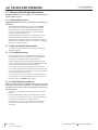
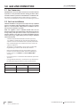
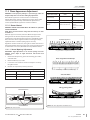
3.5.2 Vent Termination Framing
This is a cold air transfer area. The replace enclosure must comply
with all clearances as outlined in this manual, and be constructed
in compliance with local building codes. Outside walls should be
insulated to prevent cold air from entering room.
Exterior vent termination location must be in compliance with section
6.2, MINIMUM VENT TERMINATION CLEARANCES on page 16. DO
NOT RECESS THE VENT CAP INTO WALL OR SIDING.
IMPORTANT - METAL FAB VENT SYSTEM : When installing Metal Fab
vent pipe, an adapter must be used. This will increase the minimum
height for the center of the vent pipe by 3-1/4” (83mm) when framing
the wall pass through for horizontal terminations.
3.5.2.1 Clearances
• A minimum of 1” (25mm) clearance on all sides of the vertical
vent pipe must be maintained.
• A minimum of 1” (25mm) clearance from the top surface on the
horizontal pipe must be maintained.
• A minimum of 1” (25mm) clearance on the sides and bottom
surfaces on the horizontal pipe must be maintained.
3.5.2.2 Vertical Terminations
CAUTION: Cold air transfer area. The surround replace chase
must comply with all clearances as outlined in this manual, and be
constructed in compliance with local building codes. Outside walls
should be insulated to prevent cold air from entering room.
• Follow vent pipe manufacturer’s installation instructions for
vertical terminations.
• Attic insulation shields may be insulated using unfaced
insulation products listed as non-combustible per ASTM E 136.
3.5.2.3 Horizontal Terminations
IMPORTANT: Horizontal vent sections require 1/4” (6mm) rise for every
12” (305mm) of travel.
Kozy Heat’s #800-WPT3, or wall thimble products that comply with
the required 1” (25mm) clearance to combustibles must be installed
for all horizontal vent (rigid or exible) runs that pass through interior
or exterior walls. These wall thimble products may be insulated
using unfaced insulation products listed as noncombustible per
ASTM E 136.
Elbows listed with approved vent systems for this appliance vary in
vertical length. Please consult the vent manufacturer’s instructions
to determine the elbow dimension used for installation. Adjust the
wall pass-through rough opening dimensions to maintain clearance
requirements.

Rough Framing
SECTION 3 FRAMING
#SLA-42S
Rev. 11, September 2023
17
HUSSONG MFG. CO., INC. KOZY HEAT FIREPLACES
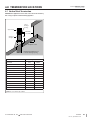
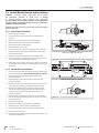
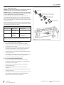
3.5.2.4 Wall Pass Through Framing
1. Measure from oor level of the replace to the center of where
the vent pipe will penetrate the wall. The dimensions in FIGURE
3.5 are used with a Simpson DuraVent elbow.
2. Cut and frame an opening in the wall to allow the vent system to
run level through the wall pass-through.
3. Follow the vent pipe manufacturer’s installation instructions for
natural draft vent installation.
• Rigid pipe dimensions in FIGURE 3.5 reect Simpson
Duravent 5” x 8” coaxial pipe. Other manufacturers product
dimensions may vary.
• Flexible pipe framing dimensions in FIGURE 3.5 reect Kozy
Heat #800 Series Flexible Vent System.
19”
(483mm)
48”
(1219mm)
MINIMUM RIGID VENT PIPE TERMINATION
NATURAL GAS
52½”
(1334mm)
19”
(483mm)
MINIMUM RIGID VENT PIPE TERMINATION
PROPANE
56”
(1422mm)
19”
(483mm)
MINIMUM HORIZONTAL FLEX VENT PIPE TERMINATION
NATURAL GAS AND PROPANE
10¾”
(273mm)
11”
(279mm)
5⁄” (138mm)
Required Wall Pass Through
Framing for 1” (25mm) Clearance
(shown with #800-WPT3)
FIGURE 3.5 Minimum Horizontal Termination Framing
Nominal 2“ x 4” framing used in enclosure framing

Outdoor Covered Fireplace Installation
SECTION 3 FRAMING
#SLA-42S
Rev. 11, September 2023
18 HUSSONG MFG. CO., INC. KOZY HEAT FIREPLACES
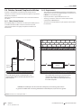
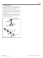
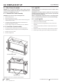
3.6 Outdoor Covered Fireplace Installation
A outdoor covered replace installation allows a replace to be
installed in an outdoor covered area, where the appliance is protected
from direct precipitation.
Follow the instructions and illustrations in this section for installation
procedures.
3.6.1 Safety Screen Barriers
Hussong Mfg. highly recommends to use black painted safety barriers
in outdoor installations. Other screen barriers that incorporate
a plated or patina nish are highly susceptible to oxidation and
discoloration.
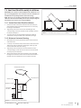
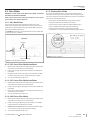
3.6.2 Requirements
• The continuous insulated building envelope and weatherproof
membrane are not to be interrupted by replace installation. See
FIGURE 3.7 on the following page.
• Fireplace operation is approved from 40°F to 110°F.
• All wiring connections shall be in accordance with outdoor
requirements of NECA NFPA 70.
• All clearances and requirements in your appliance manual must
be adhered to.
A
B
CC
The overhang (A) must be a minimum of 1/2 or
greater of the rooine elevation (B) above the base
of the replace.
The width of the overhang to each side of the
appliance (C) must be a minimum of 1/2 or
greater of the rooine elevation (B) above the
base of the replace.
EXAMPLE: If rooine (B) is 10’ above the base of replace, the overhang (A) must be 5’
or greater. The width of the overhang to EACH side of the replace (C) must be 5’ or greater.
SIDE OF
FIREPLACE
BACK OF
FIREPLACE
FRONT OF
FIREPLACE
ROOF OVERHANG
FIGURE 3.6 Outdoor Covered Fireplace Install - 1

Outdoor Covered Fireplace Installation
SECTION 3 FRAMING
#SLA-42S
Rev. 11, September 2023
19
HUSSONG MFG. CO., INC. KOZY HEAT FIREPLACES
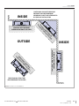
MINIMUM WEATHERPROOF
OVERHANG IN FRONT AND SIDES
MINIMUM WEATHERPROOF
OVERHANG IN FRONT AND SIDES
MINIMUM WEATHERPROOF
OVERHANG IN FRONT AND SIDES
MINIMUM WEATHERPROOF
OVERHANG IN FRONT AND SIDES
FREE STANDING STRUCTURE
(WEATHERPROOF ENCLOSURE)
CONTINUOUS INSULATED BUILDING
ENVELOPE AND WEATHERPROOF
MEMBRANE IS NOT TO BE INTERRUPTED
BY FIREPLACE INSTALLATION
INSIDE
OUTSIDE INSIDE
FIGURE 3.7 Outdoor Covered Installation - 2

Facing and Finishing Requirements
SECTION 4 FACING AND FINISHING
#SLA-42S
Rev. 11, September 2023
20 HUSSONG MFG. CO., INC. KOZY HEAT FIREPLACES
4.0 FACING AND FINISHING
4.1 Facing and Finishing Requirements
WARNING: Maintain all minimum clearances to combustibles from the
appliance and vent system.
4.1.1 Mantel Requirements
WARNING: All minimum clearances to combustible material MUST be
maintained.
• Combustible Mantel Projections - As referenced in FIGURE
4.1 on page 21, the 9” (229mm) mantel can start at 14-1/4”
(362mm) above the nishing edge. Mantel projections can
increase 1” (25mm) of depth for every 1” (25mm) of height
starting at the 9” (229mm) mantel.
• Non-combustible Mantel Projections - Minimum Vertical and
Maximum Horizontal: A minimum vertical clearance of 6”
(152mm) above the nishing edge to a maximum 6” (152mm)
depth of a non-combustible mantel. Follow projection 1” (25mm)
up for every 1” (25mm) deeper.
4.1.2 Adjacent Sidewall Requirements
• The adjacent sidewall must be 6” (152mm) from the nishing
edge of the replace.
4.1.3 Facing Requirements
• Non-combustible material is required at the top and sides of
the replace. This replace is designed to accommodate non-
combustible facing material up to 1/2” (13mm) thick.
• Install facing material up to the nishing edge that surrounds
the glass frame assembly. Do not apply any material beyond this
point. The glass frame assembly must be removable.
• Do not secure material to the bottom front cover panel with
screws, which may damage the control system components. Use
a silicone sealant that has a 300°F (149°C) continuous exposure
rating to secure material in this zone.
• It is acceptable to pre-drill holes and to use self-tapping screws
to attach the non-combustible material to the top and sides of
the replace face. See FIGURE 4.3 on page 23.
4.1.4 Finishing Recommendations
NOTE: The surface area above the appliance may be aected by high
temperatures emitted from this appliance. To help avoid or reduce the
possibility of the sheetrock to crack, Hussong Mfg. recommends the
following methods:
• Ensure the non-combustible material and sheetrock is dry and
dust free.
• For taping and mudding seams, we recommend heat resilient
tape, mesh and joint compounds, such as Durabond. Mud must
be cured as per manufacturer’s recommendations.
• For a painted surface, use a high quality acrylic latex primer
and nish coat. Avoid at or light-colored paints to prevent
discoloring.
Page is loading ...
Page is loading ...
Page is loading ...
Page is loading ...
Page is loading ...
Page is loading ...
Page is loading ...
Page is loading ...
Page is loading ...
Page is loading ...
Page is loading ...
Page is loading ...
Page is loading ...
Page is loading ...
Page is loading ...
Page is loading ...
Page is loading ...
Page is loading ...
Page is loading ...
Page is loading ...
Page is loading ...
Page is loading ...
Page is loading ...
Page is loading ...
Page is loading ...
Page is loading ...
Page is loading ...
Page is loading ...
Page is loading ...
Page is loading ...
Page is loading ...
Page is loading ...
Page is loading ...
Page is loading ...
Page is loading ...
Page is loading ...
Page is loading ...
Page is loading ...
Page is loading ...
Page is loading ...
-
 1
1
-
 2
2
-
 3
3
-
 4
4
-
 5
5
-
 6
6
-
 7
7
-
 8
8
-
 9
9
-
 10
10
-
 11
11
-
 12
12
-
 13
13
-
 14
14
-
 15
15
-
 16
16
-
 17
17
-
 18
18
-
 19
19
-
 20
20
-
 21
21
-
 22
22
-
 23
23
-
 24
24
-
 25
25
-
 26
26
-
 27
27
-
 28
28
-
 29
29
-
 30
30
-
 31
31
-
 32
32
-
 33
33
-
 34
34
-
 35
35
-
 36
36
-
 37
37
-
 38
38
-
 39
39
-
 40
40
-
 41
41
-
 42
42
-
 43
43
-
 44
44
-
 45
45
-
 46
46
-
 47
47
-
 48
48
-
 49
49
-
 50
50
-
 51
51
-
 52
52
-
 53
53
-
 54
54
-
 55
55
-
 56
56
-
 57
57
-
 58
58
-
 59
59
-
 60
60


Kozyheat Slayton 42S Owner's manual
- Category
- Fireplaces
- Type
- Owner's manual
Ask a question and I''ll find the answer in the document
Finding information in a document is now easier with AI
Related papers
-
Kozyheat Slayton 42S Owner's manual
-
kozy heat SLAYTON-36 Owner's manual
-
-
-
-
-
kozy heat Slayton 42 Owner's manual
-
-
-
Other documents
-
-
kozy heat Callaway 50 Operating instructions
-
-
kozy heat Slayton 42S Direct Vent Fireplace Operating instructions
-
Urbana U37 Installation guide
-
-
 SUPERFRONT bar 20 User manual
-
 rollease acmeda Channel Guide Installation guide

