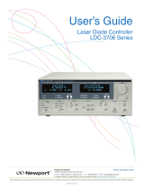
Operation and Service Manual
Laser Diode Controllers
LDC500 Series
Stanford Research Systems
Revision 4.3 •February 23, 2016

Certification
Stanford Research Systems certifies that this product met its published specifications at the time
of shipment.
Warranty
This Stanford Research Systems product is warranted against defects in materials and workman-
ship for a period of one (1) year from the date of shipment.
Service
For warranty service or repair, this product must be returned to a Stanford Research Systems
authorized service facility. Contact Stanford Research Systems or an authorized representative
before returning this product for repair.
Information in this document is subject to change without notice.
Copyright c
Stanford Research Systems, Inc., 2008 – 2016. All rights reserved.
Stanford Research Systems, Inc.
1290–D Reamwood Avenue
Sunnyvale, CA 94089 USA
Phone: (408) 744-9040 •Fax: (408) 744-9049
www.thinkSRS.com •e-mail: [email protected]
Printed in U.S.A. Document number 9-01640-903
LDC500 Series Laser Diode Controllers

Contents
General Information v
Safety and Preparation for Use ................ v
Symbols ............................. vi
Notation ............................. vii
Specifications .......................... viii
1 Overview 1 – 1
1.1 How to use this Manual ................. 1–2
1.2 Introduction to the Instrument ............. 1–2
1.2.1 Instrument architecture ............. 1–2
1.2.2 Grounding ..................... 1–5
1.3 Features and controls ................... 1–6
1.4 Power ............................ 1–6
1.4.1 Power entry module ............... 1–6
1.4.2 Grounding terminal ............... 1–6
1.4.3 Turning on power ................ 1–6
1.4.4 Hardware reset .................. 1–8
1.5 Cable Interfaces ...................... 1–8
1.5.1 Modulate ..................... 1–8
1.5.2 Sync ........................ 1–8
1.5.3 Laser diode .................... 1–8
1.5.4 TEC ......................... 1–9
1.5.5 Remote interface connections .......... 1–10
1.6 User Interface ....................... 1–10
1.6.1 Hard controls ................... 1–10
1.6.2 Dedicated displays ................ 1–11
1.6.3 Alphanumeric display .............. 1–11
1.6.4 Local/Remote ................... 1–13
2 Getting Started 2 – 1
2.1 Preparation for Use .................... 2–2
2.1.1 Power and ground ................ 2–2
2.1.2 Laser diode connections ............. 2–2
2.1.3 TEC module connections ............ 2–2
2.1.4 Checking wiring ................. 2–3
2.1.5 Turning on power ................ 2–5
i

ii Contents
2.2 Operating the TEC controller .............. 2–6
2.2.1 Sensor configuration ............... 2–6
2.2.2 TEC settings .................... 2–7
2.2.3 Verify TEC wiring polarity ........... 2–8
2.2.4 Auto-tuning .................... 2–9
2.2.5 TEC operation in CT mode ........... 2–10
2.2.6 Thermal runaway ................. 2–10
2.2.7 TEC operation in CC mode ........... 2–11
2.2.8 TEC limit values ................. 2–11
2.2.9 Monitoring the TEC ............... 2–12
2.2.10 Configuring TEC trip-offs............ 2–12
2.3 Operating the Laser Diode Driver ............ 2–14
2.3.1 Laser driver configuration ............ 2–14
2.3.2 Laser settings ................... 2–15
2.3.3 Operating the laser in CC mode ........ 2–15
2.3.4 Operating the laser in CP mode ......... 2–16
2.3.5 Modulation .................... 2–17
2.3.6 Monitoring the LD ................ 2–17
2.3.7 Optical power calibration ............ 2–18
2.3.8 Configuring LD trip-offs............. 2–18
2.4 Factory Default Settings ................. 2–19
3 Menus 3 – 1
3.1 Menu Navigation ..................... 3–2
3.2 Laser Menus ........................ 3–2
3.2.1 LD settings .................... 3–2
3.2.2 LD monitor .................... 3–4
3.2.3 LD configuration ................. 3–5
3.3 TEC Menus ........................ 3–7
3.3.1 TEC settings .................... 3–7
3.3.2 TEC monitor ................... 3–8
3.3.3 TEC configuration ................ 3–9
3.4 Other Menus ........................ 3–12
3.4.1 Utility ....................... 3–13
3.4.2 Other messages .................. 3–14
4 Remote Operation 4 – 1
4.1 Index of Common Commands .............. 4–2
4.2 Alphabetic List of Commands .............. 4–6
4.3 Introduction ........................ 4–10
4.3.1 Interface configuration .............. 4–10
4.3.2 Buffers ....................... 4–10
LDC500 Series Laser Diode Controllers

Contents iii
4.4 Ethernet .......................... 4–10
4.4.1 Connection example ............... 4–11
4.5 Commands ......................... 4–16
4.5.1 Command syntax ................. 4–16
4.5.2 Notation ...................... 4–17
4.5.3 Examples ..................... 4–17
4.5.4 Laser limit commands .............. 4–18
4.5.5 Laser setting commands ............. 4–20
4.5.6 Laser monitor commands ............ 4–22
4.5.7 Laser configuration commands ......... 4–24
4.5.8 Laser trip-offcommands ............. 4–29
4.5.9 TEC limit commands ............... 4–31
4.5.10 TEC setting commands ............. 4–33
4.5.11 TEC monitor commands ............. 4–35
4.5.12 TEC configuration commands ......... 4–36
4.5.13 TEC sensor commands .............. 4–40
4.5.14 TEC trip-offcommands ............. 4–45
4.5.15 Interface commands ............... 4–46
4.5.16 Status commands ................. 4–52
4.6 Status Model ........................ 4–57
4.6.1 Status byte (SB) .................. 4–58
4.6.2 Service request enable (SRE) .......... 4–59
4.6.3 Standard event status (ESR) ........... 4–59
4.6.4 Laser diode condition (LDCR) ......... 4–60
4.6.5 TEC controller condition (TECR) ........ 4–61
5 Error Messages 5 – 1
5.1 Laser Diode Driver Messages .............. 5–2
5.1.1 Interlock ...................... 5–2
5.1.2 Transitions with high photodiode current . . . 5 – 2
5.1.3 Transitions with limited laser current ..... 5–2
5.1.4 Transitions locked out .............. 5–2
5.1.5 Responsivity ................... 5–3
5.1.6 Photodiode current overflow .......... 5–3
5.1.7 Responsivity underflow ............. 5–3
5.1.8 Responsivity overflow .............. 5–4
5.1.9 Trip-offfromTEC................. 5–4
5.1.10 Trip-offfrom temperature ............ 5–4
5.2 TEC Messages ....................... 5–4
5.2.1 Autotune ...................... 5–4
5.2.2 No loop control .................. 5–5
5.2.3 Transitions locked out .............. 5–5
LDC500 Series Laser Diode Controllers

iv Contents
5.2.4 Temperature faults ................ 5–6
5.2.5 Thermal runaway ................. 5–6
5.2.6 Polarity change locked out ........... 5–6
5.3 Other messages ...................... 5–6
5.3.1 Restart ....................... 5–6
6 Accessories 6 – 1
6.1 Cables ........................... 6–2
6.1.1 Laser diode cables ................ 6–2
6.1.2 TEC cables ..................... 6–4
LDC500 Series Laser Diode Controllers

General Information
Safety and Preparation for Use
Dangerous voltages, capable of causing injury or death, are
WARNING present in this instrument. Do not remove the product covers
or panels. Do not apply power or operate the product without
all covers and panels in place.
AC line voltage
The LDC500 Series Laser Diode Controllers operate from a 100 V,
120 V, 220 V, or 240 V nominal AC power source having a line fre-
quency of 50 Hz or 60 Hz. Before connecting the power cord to a
power source, verify that the LINE VOLTAGE SELECTOR, located
in the rear panel power-entry module, is set so that the correct AC
line voltage value is visible.
The LDC500 Series Laser Diode Controllers will be damaged if oper-
CAUTION ated with the LINE VOLTAGE SELECTOR set for the wrong AC line
voltage, or if the wrong fuses are installed. Verify that the correct
line fuses are installed before connecting the line cord. Fuse size is
5MF “fast blow” (5×20 mm). For 100 V/120 V, use 4 A fuses; for
220 V/240 V, use 2 A fuses.
Line cord
The LDC500 Series Laser Diode Controllers have a detachable, three-
wire power cord for connection to the power source and to a protec-
tive ground. The exposed metal parts of the instrument are connected
to the outlet ground to protect against electrical shock. Always use
an outlet which has a properly connected protective ground.
Service
The LDC500 Series Laser Diode Controllers do not have any user
serviceable parts inside. Refer service to a qualified technician.
Do not install substitute parts or perform any unauthorized modi-
fications to this instrument. Contact the factory for instructions on
how to return the instrument for authorized service and adjustment.
v

vi General Information
Symbols you may Find on SRS Products
Symbol Description
Alternating current
Caution - risk of electric shock
Frame or chassis terminal
Caution - refer to accompanying documents
Earth (ground) terminal
Battery
Fuse
On (supply)
Off (supply)
LDC500 Series Laser Diode Controllers

General Information vii
Notation
The following notation will be used throughout this manual.
Unless otherwise specified in the text, LDC500 refers generally to
either the LDC500, LDC501, or LDC502 Laser Diode Controller.
A warning means that injury or death is possible if the instructions
WARNING are not obeyed.
A caution means that damage to the instrument or other equipment
CAUTION is possible.
Typesetting conventions used in this manual are:
•Front-panel buttons are set as [Button].
•Front-panel indicators are set as Overload.
•Remote command names are set as *IDN?.
•Literal text other than command names is set as OFF.
Remote command examples will all be set in monospaced font. In
these examples, data sent by the host computer to the LDC500 are set
as straight teletype font, while responses received by the host
computer from the LDC500 are set as slanted teletype font.
LDC500 Series Laser Diode Controllers

viii General Information
Specifications
All performance specifications after 1 hour warm-up at 25 ◦C ambi-
ent.
Laser diode current source
LDC500 LDC501 LDC502 Units
Output current Range, high 0–100 0–500 0–2000
low 0–50 0–250 0–1000 mA
Setpoint resolution 1 10 100 μA
Accuracy ±10 ±50 ±200 μA
DC output impedance 1 MΩmin
Thermal drift ±10 ppm/◦C max
Short-term stability (1 hr) ±5 ppm FS
Long-term stability (24 hr) ±15 ppm FS
Noise density [1]
high range 0.7 3.5 12.5
low range 0.4 1.8 6.3 nA/√Hz typ.
Wide band noise [2]
high range, high BW 0.9 4.5 25
high range, low BW 0.6 1.5 5.0
low range, high BW 0.5 2.3 10
low range, low BW 0.3 1 3.5 μA rms max
Power fail transient [3] 1 1 5 mA max
Compliance voltage Range 0.1–10 V
Resolution 10 mV
Accuracy +0.2 V
Output current limit Range, high 0–100 0–500 0–2000
low 0–50 0–250 0–1000 mA
Resolution 10 10 100 μA
Accuracy ±100 ±100 ±400 μA
LDC500 Series Laser Diode Controllers

General Information ix
LDC500 LDC501 LDC502 Units
Analog modulation Input range −10 to +10 V
Input impedance 2 kΩtyp.
Transfer function
high range, CC mode 10 50 200
low range, CC mode 5 25 100 mA/V
CP mode 500 500 1000 μA/V
Modulation bandwidth (−3 dB)[4]
high BW, CC mode DC–1.0 0.8 MHz
low BW, CC mode DC–10 kHz
high BW, CP mode DC–5 kHz
low BW, CP mode DC–100 Hz
Photodiode feedback Bias voltage 0–5 V
Photodiode current 0–5000 0–10,000 μA
Setpoint resolution [5] 0.1 μA
Accuracy [5] ±3±6μA
Trigger output TTL pulse width (negative) 10 μs
Delay [6] 0.004–1000 s
Measurement & display LD current resolution 1 10 100 μA
accuracy ±200 ppm FS
PD current resolution 0.1 μA
accuracy ±200 ppm FS
LD voltage resolution 1 mV
accuracy ±300 ppm FS
Conditions:
[1] Measured electrically at 1 kHz through a 50 Ωload (LDC500), 10 Ω
load (LDC501), 4 Ωload (LDC502) .
[2] Measured electrically with an RMS meter from 10 Hz to 1 MHz,
through a 50 Ωload (LDC500), 10 Ωload (LDC501), 4 Ωload
(LDC502).
[3] Output current change, measured with an oscilloscope, upon remov-
ing AC power cord.
[4] Bandwidth can be affected by cable and load parameters.
[5] In CP control mode.
[6] Delay programmed by the remote SYND command.
LDC500 Series Laser Diode Controllers

xGeneral Information
TEC controller
Min Typ Max Units
Temperature control Control ranges
IC sensors −55 +150
Resistance sensors −150 +250 ◦C
0.010 500 kΩ
Setpoint resolution
Temperature 0.001 ◦C
Resistance 0.1 Ω
Setpoint Accuracy [1]
Temperature ±0.01 ◦C
Resistance ±0.1 %
Stability
Thermal drift [2] ±0.0005 ◦C/◦C
Short term (1 hr) ±0.001
Long term (24 hr) ±0.002 ◦C
Control algorithm digital PID
Autotuning method open-loop step response
TEC current control Output range −4.5+4.5 A
Output power 36 W
Setpoint resolution 1 mA
Setpoint accuracy ±5 mA
Compliance voltage 8 V
Polarity software reversible
Noise and ripple [3]
1 A output 0.1
4 A output 0.2 mA rms
Limit range 0 4.5 A
Limit resolution 1 mA
Limit accuracy ±5 mA
LDC500 Series Laser Diode Controllers

General Information xi
Temperature sensors Excitation range 10, 100, 1000 μA
Thermistors 0.010 500 kΩ
RTD Pt-100, Pt-1000, and equiv
IC voltage sensors (1 mA bias) LM335 and equiv.
IC current sensors (>5 V bias) AD590 and equiv.
Measurement & display Temperature resolution 0.001 ◦C
Thermistor resolution 0.1 Ω
Accuracy [4] ±0.2%+0.05 Ω
TEC current resolution 1
Accuracy ±5 mA
TEC voltage resolution 1
Accuracy ±5 mV
Conditions:
[1] Accuracy figures represent the uncertainty added by the measure-
ment circuitry inside the instrument. Sensor uncertainty is not in-
cluded, which can add up to 2 ◦C.
[2] Measured by a monitor thermistor on the TEC stage. The LDC500 is
operated in an environmental chamber between 0 ◦C and 40 ◦C. The
TEC and heatsink are at room temperature.
[3] Measured output current noise from 10 Hz to 1 MHz.
[4] With 1 mA excitation current
General characteristics
Interface GPIB (IEEE-488.2), RS-232, Ethernet/TCP-IP
Connectors DB9-F (laser diode), DB15-F (TEC),
BNC (modulate in, trigger out)
Power 100 W, 100 V, 120 V, 220 V, 240 V
50 Hz or 60 Hz
Fuse Type 5MF, 5×20 mm, “fast blow”
4 A (100 V −120 V); 2 A (220 V −240 V)
Weight 15 lbs
Dimensions 8.5 W×5 H×15 D
LDC500 Series Laser Diode Controllers

xii General Information
LDC500 Series Laser Diode Controllers

1 Overview
This chapter provides a basic overview of the LDC500 Series Laser
Diode Controllers.
In This Chapter
1.1 How to use this Manual ................. 1–2
1.2 Introduction to the Instrument ............. 1–2
1.2.1 Instrument architecture ............. 1–2
1.2.2 Grounding ..................... 1–5
1.3 Features and controls .................. 1–6
1.4 Power ............................ 1–6
1.4.1 Power entry module ............... 1–6
1.4.2 Grounding terminal ............... 1–6
1.4.3 Turning on power ................ 1–6
1.4.4 Hardware reset .................. 1–8
1.5 Cable Interfaces ...................... 1–8
1.5.1 Modulate ..................... 1–8
1.5.2 Sync ........................ 1–8
1.5.3 Laser diode .................... 1–8
1.5.4 TEC ......................... 1–9
1.5.5 Remote interface connections .......... 1–10
1.6 User Interface ....................... 1–10
1.6.1 Hard controls ................... 1–10
1.6.2 Dedicated displays ................ 1–11
1.6.3 Alphanumeric display .............. 1–11
1.6.4 Local/Remote ................... 1–13
1–1

1–2 Overview
1.1 How to use this Manual
All users new to the LDC500 should begin with section 1.2 of this
chapter, to familiarize themselves with the basic architecture and
grounding scheme for the product. Section 1.6 provides an introduc-
tion to the user interface, and will also benefit new users.
Chapter 2 provides step-by-step examples for a new user getting
started with the LDC500, and is a good starting point for users al-
ready familiar with the basics of the user interface.
Chapter 3 provides a comprehensive treatment of the user interface
menu structure, with complete lists of all the parameter items.
Chapter 4 discusses remote operation of the LDC500, over RS-232,
GPIB, and ethernet. Many of the menu items discussed in chapter 3
refer to more detailed information here.
1.2 Introduction to the Instrument
The LDC500 Series Laser Diode Controllers are combination preci-
sion current source and temperature controllers. The current source,
intended to provide power to a laser diode (LD), provides a low noise,
high stability output with programmable current and voltage limits.
The temperature controller operates with most commonly used tem-
perature sensors and thermoelectric coolers (TEC) to maintain pre-
cision thermal control of the laser.Multiple remote interfaces–GPIB,
RS-232, and ethernet–give you complete control of the instrument
from your computer.
1.2.1 Instrument architecture
The LDC500 is logically divided into two functional sections, the
LD Driver and the TEC Controller, with a common control and in-
terface section for front-panel and remote operation. All three of
these sections are electrically isolated from each other, with only the
control/interface section electrically grounded to chassis ground.
A block diagram of the LDC500, showing the arrangement of
independently-isolated power sources, is given in Figure 1.1.
1.2.1.1 Laser diode driver
The primary function of the LD driver is providing stable, low-noise
electrical current to bias a laser into emission. This excitation is de-
livered by a low-noise current source circuit. The current source
has two range settings, with a maximum current commandable be-
tween 50 mA and 100 mA (LDC500), 250 mA and 500 mA (LDC501),
LDC500 Series Laser Diode Controllers

1.2 Introduction to the Instrument 1–3
CPUand
Display
TEC
Controller
TEC
sensor
LDDriver
P/S
P/S
P/S
P/S
LD
Modulate
PD
GPIB,etc
SyncOut
PDbias
Figure 1.1: The LDC500 power supply block diagram.
Vpower
+
Modulate
Laser Diode
Current Source
SVLM = user setting for LD Voltage limit
SILM = user setting for LD Current limit
Vpower = SVLM + (2.8ohm * SILM) + 0.55V
Photodiode
Bias/Amp
LD ANODE(+)
LD CATHODE (-)
PD CATHODE (-)
PD ANODE (+)
LD
LD
LD
J250
BNC
Photodiode
2k
Modulate OFF
U250A
2
3
6
Laser
Figure 1.2: The laser diode drive circuitry (simplified).
or 1000 mA and 2000 mA (LDC502). For both ranges, there are two
control modes for the magnitude of the current source output: con-
stant current (CC), and constant optical power (CP). A simplified
circuit diagram is in Figure 1.2.
Operating in CC mode, the LDC500 programs the desired current
magnitude, in milliamps.To operate in CP mode, a monitor pho-
todiode must be used to measure the output intensity of the laser
diode. In CP mode, the LDC500 measures this photodiode current,
and continuously adjusts (servos) the LD current source to maintain
a constant photodiode current. Since the photodiode current is pro-
portional to optical power, this operating mode stabilizes the laser’s
LDC500 Series Laser Diode Controllers

1–4 Overview
output power optically. The CP setpoint can be given either in raw
microamps of photodiode current, or in optical power as milliwatts
(given a photodiode responsivity value).
For both ranges and operating modes of the LD driver, a DC-coupled
analog modulation input is available on the front panel. Modulation
can be used on all ranges and operating modes, and can be configured
for low or high bandwidth. When unused, the modulation input
relay should be opened by setting “Modulate enable” to “N” in the
Laser Configure menu. Commanding the modulation input offin
this way, when not in use, will result in slightly lower current noise.
1.2.1.2 TEC controller
The TEC controller section of the LDC500 delivers high performance
temperature control for thermally stabilizing the laser diode. Most
commonly-used thermal sensors are supported, including thermis-
tors, RTDs, LM335-class voltage-output IC sensors, and AD590-class
current-output IC sensors. A 36 W, ±4.5 A bipolar current source
drives the thermoelectric cooler (TEC) module of the laser. A block
diagram of the TEC circuitry is in Figure 1.3.
TEC
Controller
sensor
readout
TEC
Current
Source
+
–
MCU
TEC
t
LM335 AD590
Figure 1.3: The TEC controller (simplified).
Two operating modes are available for the TEC controller. In constant
temperature (CT) mode, a digital proportional-integral-differential
(PID) control algorithm adjusts the TEC output current to maintain
the temperature sensor at a desired temperature. For characteriz-
ing TEC modules, a second operating mode–constant current (CC)–
LDC500 Series Laser Diode Controllers

1.2 Introduction to the Instrument 1–5
allows the user to set the TEC current at a constant value. Four wire
connections to the TEC module allow accurate voltage sensing in-
dependent of resistive losses in the current leads, allowing for more
accurate device characterization.
For best temperature control, the autotuning feature of the LDC500
should be used. This will optimize the P,I, and Dfeedback param-
eters for the temperature control loop; the user can then inspect and
modify the loop parameters for best operation if necessary.
1.2.2 Grounding
For maximum user flexibility, many sections of the LDC500 are elec-
trically isolated from chassis ground, and from each other. In par-
ticular, the LD current source and the TEC controller are separately
floated. SRS recommends operating the laser diode, and the TEC
module, floating without connection to ground. Note that many laser
packages ground one terminal of the laser (either anode or cathode)
to the package case. We still recommend configurations where the
package case does not connect to ground. In situations where the
laser case must be connected to ground, be careful to understand all
potential ground paths in your system to avoid inadvertant ground
loops or short circuits.
The monitor photodiode, if any, will perform best if also left floating,
or one terminal can be tied to one of the laser diode terminals. How-
ever, do not separately ground one of the photodiode terminals, as
this will interfere with the proper function of the laser diode driving
circuitry.
1.2.2.1 Grounding and modulation
It is important that the user understand the internal grounding ar-
rangement of the LDC500 when using analog modulation with a
ground-referenced laser diode. As can be seen in Figure 1.2, the cen-
ter and outer conductors of the Modulate BNC input are received
differentially by an input amplifier which then modulates the LD
current source. The “ground” symbol in the figure, labeled “LD”,
is not chassis ground or any other externally-referenced potential; it
is simply an internal reference potential for the LD current source.
If the user’s laser is isolated from ground, then an earth-referenced
signal connected to the Modulate BNC will cause the “LD ground”
to come to earth.
If either the LD cathode, or the LD anode, is tied to earth, however,
then the internal node “LD ground” will be biased at a definite, neg-
ative potential relative to earth. The differential input circuit (formed
LDC500 Series Laser Diode Controllers

1–6 Overview
by resistors R269 and R255) will still allow correct modulation con-
trol with an earth-referenced modulation signal, but it now becomes
more important that the modulation source has a balanced output
impedance. If the modulation source has a 50 Ωoutput impedance
(on the center conductor of the BNC), with the outer shield at earth
(low impedance), then a “common-mode” DC error, of the order of
up to 1 mA, may be induced. The user has 4 strategies to avoid this
effect:
1. Keep the laser diode fully floating,
2. Use a floating source for the modulation input,
3. Ensure the modulation source has a low output impedance, or
4. Balance the modulation source impedance.
1.3 Features and controls
The remaining sections in this chapter explains each part of the front
and rear panel of the LDC500. Circled numbers in the left margin
refer to Figure 1.4.
1.4 Power
1.4.1 Power entry module
A rear-panel power entry module contains a standard IEC-C13 power
connector.The power cord shipped with your LDC500 mates with the
14
power entry module, and should match the standard wall sockets for
your locale. The fuse and voltage selector is also in the power entry
block, and must show the correct voltage setting for your location.
See page v for details on fuse and voltage selection.
1.4.2 Grounding terminal
A dedicated chassis ground terminal is adjacent to the power entry
module.
13
1.4.3 Turning on power
Power to the LDC500 is controlled by the front-panel keyswitch. In
order to turn on the instrument,the key must be inserted and rotated
1
clockwise to the “1” position. The key cannot be removed when in
this position.
LDC500 Series Laser Diode Controllers
Page is loading ...
Page is loading ...
Page is loading ...
Page is loading ...
Page is loading ...
Page is loading ...
Page is loading ...
Page is loading ...
Page is loading ...
Page is loading ...
Page is loading ...
Page is loading ...
Page is loading ...
Page is loading ...
Page is loading ...
Page is loading ...
Page is loading ...
Page is loading ...
Page is loading ...
Page is loading ...
Page is loading ...
Page is loading ...
Page is loading ...
Page is loading ...
Page is loading ...
Page is loading ...
Page is loading ...
Page is loading ...
Page is loading ...
Page is loading ...
Page is loading ...
Page is loading ...
Page is loading ...
Page is loading ...
Page is loading ...
Page is loading ...
Page is loading ...
Page is loading ...
Page is loading ...
Page is loading ...
Page is loading ...
Page is loading ...
Page is loading ...
Page is loading ...
Page is loading ...
Page is loading ...
Page is loading ...
Page is loading ...
Page is loading ...
Page is loading ...
Page is loading ...
Page is loading ...
Page is loading ...
Page is loading ...
Page is loading ...
Page is loading ...
Page is loading ...
Page is loading ...
Page is loading ...
Page is loading ...
Page is loading ...
Page is loading ...
Page is loading ...
Page is loading ...
Page is loading ...
Page is loading ...
Page is loading ...
Page is loading ...
Page is loading ...
Page is loading ...
Page is loading ...
Page is loading ...
Page is loading ...
Page is loading ...
Page is loading ...
Page is loading ...
Page is loading ...
Page is loading ...
Page is loading ...
Page is loading ...
Page is loading ...
Page is loading ...
Page is loading ...
Page is loading ...
Page is loading ...
Page is loading ...
Page is loading ...
Page is loading ...
Page is loading ...
Page is loading ...
Page is loading ...
Page is loading ...
Page is loading ...
Page is loading ...
Page is loading ...
Page is loading ...
Page is loading ...
Page is loading ...
Page is loading ...
Page is loading ...
Page is loading ...
Page is loading ...
Page is loading ...
Page is loading ...
Page is loading ...
Page is loading ...
Page is loading ...
Page is loading ...
Page is loading ...
Page is loading ...
Page is loading ...
Page is loading ...
Page is loading ...
Page is loading ...
Page is loading ...
Page is loading ...
Page is loading ...
Page is loading ...
Page is loading ...
Page is loading ...
Page is loading ...
/
