Page is loading ...

MICRO-EPSILON MESSTECHNIK GmbH & Co. KG
Koenigbacher Str. 15 · 94496 Ortenburg / Germany
Tel. +49 (0) 8542 / 168-0 · Fax +49 (0) 8542 / 168-90
[email protected] · www.micro-epsilon.com
Your local contact: www.micro-epsilon.com/contact/worldwide/
P60
P96
P115
P200
Operating Instructions
wireSENSOR WDS

Declaration of Incorporation
Declaration of incorporation according to the EC Machinery Directive 2006/42/EC, Annex II B
The manufacturer and person authorized to compile the relevant technical documents
MICRO-EPSILON MESSTECHNIK
GmbH & Co. KG
Königbacher Straße 15
94496 Ortenburg / Germany
hereby declare that the machine designated below complies with the relevant fundamental health and safety require-
ments of the EC Machinery Directive, including modifications to it applicable at the time of this declaration, based on its
design and construction and in the version put on the market by us – to the extent that the scope of supply allows.
Machine design: Draw-wire sensor (mechanics and models with potentiometer output)
Type designation: WDS-xxx, WPS-xxx
The following fundamental health and safety requirements according to Annex I of the directive specified above have
been applied and complied with:
- No. 1.1.2. Principles of safety integration
- No. 1.7.3. Marking of machinery
- No. 1.7.4. Operating instructions

Furthermore, we declare compliance with the following directives and standards including the modifications applicable
at the time this declaration is made:
- Directive 2006/42/EC (machinery)
EN ISO 13857:2019 Safety of machinery - Safety distances to prevent hazard zones being reached by upper and
lower limbs
EN 60204-1:2018 Safety of machinery - Electrical equipment of machines - Part 1: General requirements
- Directive 2011/65/EU (RoHS)
EN IEC 63000:2018 Technical documentation for the assessment of electrical and electronic devices with respect to
the restriction of hazardous substances
We also declare that the special technical documentation for this partially completed machine has been created in accor-
dance with Annex VII, Part B, and commit ourselves to disclose this to the market surveillance authorities upon request.
The commissioning of these partially completed machines is prohibited until the partially completed machine(s) has/
have been installed in a machine that meets the requirements of the EC Machinery Directive and for which an EU Decla-
ration of Conformity according to Annex II, Part A exists.
Ortenburg, Germany Dipl.-Ing.(FH) Eduard Huber, MBA
July 1, 2021 Quality Manager
Fax +49 (0) 8542 / 168-90 www.micro-epsilon.com

wireSENSOR, WDS P60/P96/P115/P200
Contents
1. Safety ........................................................................................................................................ 7
1.1 Symbols Used ................................................................................................................................................. 7
1.2 Warnings .......................................................................................................................................................... 7
1.3 Notes on CE Marking ...................................................................................................................................... 8
1.4 Intended Use ................................................................................................................................................... 9
1.5 Proper Environment ......................................................................................................................................... 9
1.6 Foreseeable Misuse ......................................................................................................................................... 9
2. Functional Principle, Technical Data ..................................................................................... 10
2.1 Functional Principle ....................................................................................................................................... 10
2.2 Structure, Electrical Connection .................................................................................................................... 10
2.3 Technical Data Model P60 Analog................................................................................................................. 11
2.4 Technical Data Model P96 Analog................................................................................................................. 12
2.5 Technical Data Model P115 Analog............................................................................................................... 13
2.6 Technical Data Model P60 Digital .................................................................................................................. 16
2.7 Technical Data Model P96 Digital .................................................................................................................. 17
2.8 Technical Data Model P115 Digital ................................................................................................................ 18
2.9 Technical Data Model P200 Digital ................................................................................................................ 19
3. Delivery ................................................................................................................................... 20
3.1 Unpacking/Included in Delivery ................................................................................................................... 20
3.2 Storage .......................................................................................................................................................... 20
4. Installation and Mounting ...................................................................................................... 21
4.1 Precautions .................................................................................................................................................... 21
4.2 Sensor Assembly ........................................................................................................................................... 21
4.3 Dimensional Drawings ................................................................................................................................... 22
4.3.1 wireSENSOR WDS P60 Analog ................................................................................................... 22
4.3.2 wireSENSOR WDS P60 Digital ..................................................................................................... 24
4.3.3 wireSENSOR WDS P96 Analog ................................................................................................... 26
4.3.4 wireSENSOR WDS P96 Digital ..................................................................................................... 28
4.3.5 wireSENSOR WDS P115 Analog ................................................................................................. 30
4.3.6 wireSENSOR WDS P115 Digital ................................................................................................... 32
4.3.7 wireSENSOR WDS P200 Digital ................................................................................................... 34

Deutsch
wireSENSOR, WDS P60/P96/P115/P200
4.4 Guiding and Attaching the Wire .................................................................................................................... 36
4.5 Pin Assignment Analog ................................................................................................................................. 37
4.5.1 Potentiometer Output ................................................................................................................... 37
4.5.2 Voltage Output .............................................................................................................................. 38
4.5.3 Current Output .............................................................................................................................. 38
4.6 Pin Assignment Digital ................................................................................................................................... 40
4.6.1 TTL, HTL ....................................................................................................................................... 40
4.6.2 SSI ................................................................................................................................................ 42
4.6.3 CANopen ...................................................................................................................................... 44
4.6.4 PROFIBUS DP .............................................................................................................................. 46
4.6.5 EtherNet/IP ................................................................................................................................... 48
4.6.6 EtherCAT....................................................................................................................................... 50
5. Operation ................................................................................................................................ 52
6. Operation and Maintenance .................................................................................................. 52
7. Disclaimer ............................................................................................................................... 53
8. Service, Repair ....................................................................................................................... 54
9. Decommissioning, Disposal .................................................................................................. 55
Appendix
A 1 Accessories and Spare Parts ................................................................................................ 56
A 2 Cable Connection and Color Code Connection Cable PC3/8-WDS .................................... 57
A 3 Drawings and References for Attachment ............................................................................ 58

wireSENSOR, WDS P60/P96/P115/P200

Page 7
Safety
wireSENSOR, WDS P60/P96/P115/P200
1. Safety
System operation assumes knowledge of the operating instructions.
1.1 Symbols Used
The following symbols are used in these operating instructions:
Indicates a hazardous situation which, if not avoided, may result in minor or mode-
rate injury.
Indicates a situation that may result in property damage if not avoided.
Indicates a user action.
iIndicates a tip for users.
1.2 Warnings
The supply voltage must not exceed the specified limits.
> Risk of injury
> Damage to or destruction of the sensor
Do not open the sensor housing.
> Risk of injury from pre-tensioned spring motor
Do not pull or loop the measuring wire around unprotected parts of the body.
> Risk of injury
Do not let the measuring wire rewind without control (snap back).
> Risk of injury due to whiplash of the measuring wire with wire clip / eyelet
> Destruction of the measuring wire and/or the sensor
Do not pull the measuring wire over measuring range.
> Risk of injury

Page 8
Safety
wireSENSOR, WDS P60/P96/P115/P200
> Destruction of the measuring wire and/or the sensor
Connect the power supply and the display/output device according to the safety regulations for electrical
equipment.
> Damage to or destruction of the sensor
Avoid shocks and impacts to the sensor.
> Damage to or destruction of the sensor
1.3 Notes on CE Marking
For WDS draw-wire displacement sensors with voltage, current, digital or encoder outputs, the
EU Directives 2014/30/EU, 2011/65/EU shall apply. In addition, the Machinery Directive is taken into consider-
ation (2006/42/EC).
These sensors carry the CE mark and satisfy the requirements of the EU Directives cited and the European
harmonized standards (EN) listed therein.
The EU Declaration of Conformity is available to the responsible authorities at:
MICRO-EPSILON MESSTECHNIK
GmbH & Co. KG
Königbacher Straße 15
94496 Ortenburg / Germany
Draw-wire displacement sensors with potentiometer output are devices (components) which cannot be oper-
ated autonomously and do not carry a CE mark. For WDS draw-wire displacement sensors with potentiome-
ter output, the directives 2006/42/EC and 2011/65/EU shall apply. Therefore, an EU Declaration of Conformity
is not issued according to EMC law and the Machinery Directive. The Declaration of Incorporation shall apply.
Sources: EMVG (Electromagnetic Compatibility of Equipment law), guidelines on the application of Directive
2014/35/EU, Directive 2006/42/EC.

Page 9
Safety
wireSENSOR, WDS P60/P96/P115/P200
1.4 Intended Use
Draw-wire sensors are used for
- distance or displacement measuring
- position determination of components or moving machine parts.
- The sensors must only be operated within the limits specified in the technical data, see 2.
- Draw wire sensors must be used in such a way that no persons are endangered or machines and other
material goods are damaged in the event of malfunction or total failure of the sensor.
- Take additional precautions for safety and damage prevention in case of safety-related applications.
1.5 Proper Environment
- Protection class Sensor: IP65 1
- Temperature range:
Operation: -20 ... +80 °C (-4 ... +176 °F)
Storage: -20 ... +80 °C (-4 ... +176 °F)
- Humidity: 5 ... 95 % (non-condensing)
- Ambient pressure: Atmospheric pressure
- Vibration: According to DIN EN 60068-2-6
- Mechanischer Schock: According to DIN EN 60068-2-27
i Note the slight power dissipation of the potentiometer above +40 °C (+104 °F)! (-0.15 W/10 K)
1.6 Foreseeable Misuse
Do not pull the measuring wire beyond the measuring range listed. This causes then wire to break and thus
uncontrolled snapping of the measuring wire. Risk of injury.
Do not have sensor held by a second person while the measuring wire is pulled out. Risk of snapping and
injury.
1) Models with male plug connection only with gasketed female plug

Page 10
Functional Principle, Technical Data
wireSENSOR, WDS P60/P96/P115/P200
2. Functional Principle, Technical Data
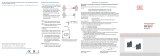
2.1 Functional Principle
With the wire principle, a linear motion is transformed
into a change in resistance by a rotation.
A measuring wire made of highly flexible stainless steel
wires is wound onto a drum with the aid of a long life
spring motor.
The winding drum is coupled axially with a
- multi-turn potentiometer (Type WDS - ... - Pxx- ... -
P/U/I) respectively with an
- encoder (Type WDS - ... - Pxx - ... - E/A).
2.2 Structure, Electrical Connection
The draw wire principle is used in the housing
design P60, P96, P115 and P200 with different
measuring lengths from 100 to 50,000 mm (3.93 to
1963.5 inches).
Five versions of the electrical connection are possible
- Potentiometer output (resistance divider)
- Voltage output (with integrated electronics)
- Current output (with integrated electronics)
- Incremental encoder (with integrated electronics,
output: HTL, TTL)
- Absolute encoder (with integrated electronics,
output: SSI, PROFINET, Profibus DP, CANopen,
EtherNet/IP, EtherCAT)
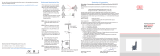
Fig. 1 Draw-wire sensor with potentiometer
Electrical connection
Measuring range
Output up to
5,000 mm
up to
7,500 mm
P CA SA
U/I SR SA
HTL/TTL CR CR
SSI SR SR
PROFINET BH BH
Profibus DP BH BH
CANopen BH BH
EtherNet/IP BH BH
EtherCAT BH BH

Page 11
Functional Principle, Technical Data
wireSENSOR, WDS P60/P96/P115/P200
2.3 Technical Data Model P60 Analog
Model WDS 100-P60 150-P60 300-P60 500-P60 750-P60 1000-P60 1500-P60
Measuring range 100 mm 150 mm 300 mm 500 mm 750 mm 1000 mm 1500 mm
Analog output Potentiometer, current, voltage
Resolution quasi infinite
Linearity
Hybrid pot. P10 ≤ ±0.1 % FSO - - - ≤ +0.5 mm ≤ +0.75 mm ≤ +1 mm ≤ +1.5 mm
Hybrid pot. P25 ≤ ±0.25 % FSO - - ≤ +0.75 mm - - - -
Conductive
plastic pot. /
Wire-wound-
pot. P25
≤ ±0.5 % FSO ≤ +0.5 mm ≤ +0.75 mm - - - - -
Sensor element Conductive plastic /
wire-wound-potentiometer Hybrid potentiometer
Wire extension force (max.) approx. 7.5 N approx. 5.5 N approx. 7.5 N approx. 7.5 N approx. 5.5 N approx. 7.5 N approx. 5.5 N
Wire retraction force (min.) approx. 6.5 N approx. 4.5 N approx. 6 N approx. 6 N approx. 4 N approx. 5 N approx. 3.5 N
Wire acceleration (max.) approx. 10 - 15 g (depends on measuring range)
Material Housing Aluminum
Measuring wire Polyamide-coated stainless steel (Ø 0.45 mm)
Wire mounting Wire clip
Mounting Mounting nuts on sensor housing
Tempera-
ture range
Storage -20 … +80 °C (-4 ... +176 °F)
Operation -20 … +80 °C (-4 ... +176 °F)
Connection Potentiometer Integrated cable, radial, length 1 m
Current, voltage Pluggable cable via 8-pin flange connector (DIN45326), radial
Shock (DIN-EN 60068-2-27) 50 g / 10 ms in 3 axes, 1000 shocks each
Vibration (DIN-EN 60068-2-6) 20 g / 10 … 2000 Hz in 3 axes, 10 Zyklen each
Protection class (DIN-EN 60529) IP65 1
Weight approx. 370 g
FSO = Full Scale Output
1) With plug version only when connected.

Page 12
Functional Principle, Technical Data
wireSENSOR, WDS P60/P96/P115/P200
2.4 Technical Data Model P96 Analog
Model WDS 2000-P96 2500-P96
Measuring range 2000 mm 2500 mm
Analog output Potentiometer, current, voltage
Resolution quasi infinite
Linearity ≤ ±0.1 % FSO ≤ ±2 mm ≤ ±2.5 mm
Sensor element Hybrid potentiometer
Wire extension force (max.) approx. 11 N approx. 9 N
Wire retraction force (min.) approx. 7.5 N approx. 5.5 N
Wire acceleration (max.) ca. 8 g
Material Housing Aluminum
Measuring wire Polyamid-coated stainless steel (Ø 0.8 mm)
Wire mounting Wire clip
Mounting Mounting nuts on sensor housing
Temperature
range
Storage -20 … +80 °C (-4 ... +176 °F)
Operation -20 … +80 °C (-4 ... +176 °F)
Connection
Potentiometer Integrated cable, axial, length 1 m
Current, voltage Pluggable cable via 8-pin flange connector
(DIN45326), radial
Shock (DIN-EN 60068-2-27) 50 g / 10 ms in 3 axes, 1000 shocks each
Vibration (DIN-EN 60068-2-6) 20 g / 20 … 2000 Hz in 3 axes, 10 cycles each
Protection class (DIN-EN 60529) IP65 1
Weight approx. 1.1 kg
FSO = Full Scale Output
1) With plug version only when connected.

Page 13
Functional Principle, Technical Data
wireSENSOR, WDS P60/P96/P115/P200
2.5 Technical Data Model P115 Analog
Model WDS 3000-P115 4000-P115 5000-P115 7500-P115 10000-P115 15000-P115
Measuring range 3000 mm 4000 mm 5000 mm 7500 mm 10000 mm 15000 mm
Analog output Potentiometer, current, voltage
Resolution quasi infinite
Linearity ≤ ±0.1 % FSO ≤ +3 mm -----
≤ ±0.15 % FSO -≤ +6 mm ≤ +7.5 mm ≤ +11.3 mm- ≤ +15 mm ≤ +22.5 mm
Sensor element Hybrid potentiometer
Wire extension force (max.) approx. 8 N approx. 8.5 N approx. 9 N approx. 24 N approx. 21 N approx. 25 N
Wire retraction force (min.) approx. 4 N approx. 4 N approx. 4 N approx. 8 N approx. 8 N approx. 8 N
Wire acceleration (max.) ca. 6 g
Material Housing Aluminum
Measuring wire Polyamide-coated stainless steel (Ø 0.45 mm) Polyamide-coated stainless steel (Ø 1 mm)
Wire mounting Wire clip
Mounting Mounting nuts on sensor housing
Temperature range Storage -20 … +80 °C (-4 ... +176 °F)
Operation -20 … +80 °C (-4 ... +176 °F)
Connection Potentiometer Integrated cable, axial, length 1 m
Current, voltage Pluggable cable via 8-pin flange connector (DIN45326), radial
Shock (DIN-EN 60068-2-27) 50 g / 10 ms in 3 axes, 1000 shocks each
Vibration (DIN-EN 60068-2-6) 20 g / 20 … 2000 Hz in 3 axes, 10 cycles each
Protection class (DIN-EN 60529) IP65 1
Weight ca. 1.1 kg ca. 2.2 kg ca. 3.2 kg ca. 3.5 kg
FSO = Full Scale Output
1) With plug version only when connected.

Page 14
Functional Principle, Technical Data
wireSENSOR, WDS P60/P96/P115/P200
Models with potentiometric output WDS - .... - Pxx - CR - P
Electrical data
Supply voltage: max. 32 VDC at 1 kOhm / max. 1 W
Resistance: 1 kOhm ±10 % (potentiometer)
Viper current: £3 mA
Temperature coefficient: ±0.0025 % FSO/K (±0.0014 % FSO/°F)
Sensitivity: Depends on measuring range, individually reported on product label
Electrical connection: Integral cable, radial, 3 wire, 1 m long
i Note the slight power dissipation of the potentiometer above +40 °C (+104 °F)! (-0.15 W/10 K)
Models with voltage output WDS - .... - Pxx - SR - U
Electrical data
Supply voltage: 14 ... 27 VDC non stabilized
Current consumption: 30 mA max.
Output voltage: 0 ... 10 VDC (Options: 0 - 5 / ±5 V)
Output current: 2 mA max.
Load impedance: > 5 kOhm
Output noise: 0.5 mVeff
Temperature coefficient: ±0.005 % FSO/K (±0.0028 % FSO/°F)
Adjustment ranges
Zero: ±20 % FSO
Sensitivity: ±20 %
Electromagnetic

Page 15
Functional Principle, Technical Data
wireSENSOR, WDS P60/P96/P115/P200
Models with current output (2-wire) WDS - .... - Pxx - SR - I
Electrical data
Supply voltage: 14 ... 27 VDC non stabilized (measured on the input terminal of the sensor)
Current consumption: 35 mA max.
Output current: 4 ... 20 mA
Load: < 600 Ohm
Temperature coefficient: ±0.01 % FSO/K (±0.005 % FSO/°F)
Output noise: < 1.6 µAeff
Adjustment ranges
Zero: ±18 % FSO
Sensitivity: ±15 %

Page 16
Functional Principle, Technical Data
wireSENSOR, WDS P60/P96/P115/P200
2.6 Technical Data Model P60 Digital
Model WDS 1000-P60 1500-P60
Measuring range 1000 mm 1500 mm
Digital interface PROFINET, Profibus DP, CANopen, EtherNet/IP,
EtherCAT
Digital output HTL, TTL, SSI
Resolution
HTL, TTL 0.067 mm (15 pulse/mm) 0.1 mm (10 pulse/mm)
SSI, PROFINET, Profibus DP,
CANopen, EtherNet/IP, EtherCAT 0.012 mm 0.018 mm
Linearity ≤ ±0.02 % FSO ≤ ±0.2 mm ≤ ± 0.3 mm
Sensor element Incremental encoder
Wire extension force (max.) approx. 7.5 N approx. 5.5 N
Wire retraction force (min.) approx. 5 N approx. 3.5 N
Wire acceleration (max.) approx. 10 g approx. 15 g
Material Housing Aluminum
Measuring wire Polyamid-coated stainless steel (Ø 0.45 mm)
Wire mounting Wire clip
Mounting Mounting nuts on sensor housing
Tempera-
ture range
Storage -20 … +80 °C (-4 ... +176 °F)
Operation -20 … +80 °C (-4 ... +176 °F)
Connection
HTL, TTL Integrated cable, radial, length 1 m
SSI 12-pin flange connector, radial
PROFINET, Profibus DP, CANopen,
EtherNet/IP, EtherCAT
Bus cover
Shock (DIN-EN 60068-2-27) 50 g / 10 ms in 3 axes, 1000 shocks each
Vibration (DIN-EN 60068-2-6) 20 g / 10 … 2000 Hz in 3 axes, 10 cycles each
Protection class (DIN-EN 60529) IP65 1
Weight approx. 1 kg
FSO = Full Scale Output
1) With plug version only when connected.

Page 17
Functional Principle, Technical Data
wireSENSOR, WDS P60/P96/P115/P200
2.7 Technical Data Model P96 Digital
Model WDS 3000-P96
Measuring range 3000 mm
Digital interface PROFINET, Profibus DP, CANopen,
EtherNet/IP, EtherCAT
Digital output HTL, TTL, SSI
Resolution
HTL, TTL 0.087 mm (11.53 pulse/mm)
SSI, PROFINET, Profibus DP, CANopen,
EtherNet/IP, EtherCAT 0.032 mm
Linearity ≤ ±0.02 % FSO ≤ ±0.6 mm
Sensor element Incremental / absolute encoder
Wire extension force (max.) approx. 11 N
Wire retraction force (min.) approx. 7.5 N
Wire acceleration (max.) approx. 8 g
Material Aluminum
Polyamid-coated stainless steel (Ø 0,8 mm)
Wire mounting Wire clip
Mounting Mounting nuts on sensor housing
Temperature range Storage -20 … +80 °C (-4 ... +176 °F)
Operation -20 … +80 °C (-4 ... +176 °F)
Connection
HTL, TTL Integrated cable, radial, length 1 m
SSI 12-pin flange connector, radial
PROFINET, Profibus DP, CANopen,
EtherNet/IP, EtherCAT
Bus cover
Shock (DIN-EN 60068-2-27) 50 g / 10 ms in 3 axes, 1000 shocks each
Vibration (DIN-EN 60068-2-6) 20 g / 20 … 2000 Hz in 3 axes, 10 cycles each
Protection class (DIN-EN 60529) IP65 1
Weight approx. 1.7 kg
FSO = Full Scale Output
1) With plug version only when connected.

Page 18
Functional Principle, Technical Data
wireSENSOR, WDS P60/P96/P115/P200
2.8 Technical Data Model P115 Digital
Model WDS 5000-P115 7500-P115 10000-P115 15000-P115
Measuring range 5000 mm 7500 mm 10000 mm 15000 mm
Digital interface PROFINET, Profibus DP, CANopen, EtherNet/IP, EtherCAT
Digital output HTL, TTL, SSI
Resolution
HTL, TTL 0.105 mm (9.52 pulse/mm)
SSI, PROFINET, Profibus DP,
CANopen, EtherNet/IP, EtherCAT 0.038 mm
Linearity ≤ ±0.01 % FSO - - ≤ ±1 mm ≤ ±1.5 mm
≤ ±0.02 % FSO ≤ ±1 mm ≤ ±1.5 mm - -
Sensor element Incremental / absolute encoder
Wire extension force (max.) approx. 16 N approx. 24 N approx. 21 N approx. 25 N
Wire extension force (min.) approx. 4 N approx. 8 N approx. 8 N approx. 8 N
Wire acceleration (max.) approx. 5 g approx. 6 g approx. 3 g approx. 3 g
Material Housing Aluminum
Measuring wire Polyamid-coated stainless steel (Ø 1 mm)
Wire mounting Eyelet (Ø 20.2 mm)
Mounting Mounting nuts on sensor housing
Temperature
range
Storage -20 … +80 °C (-4 ... +176 °F)
Operation -20 … +80 °C (-4 ... +176 °F)
Connection
HTL, TTL Integrated cable, radial, length 1 m
SSI 12-pin flange connector, radial
PROFINET, Profinet DP, CANopen Bus cover
Shock (DIN-EN 60068-2-27) 50 g / 10 ms in 3 axes, 1000 shocks each
Vibration (DIN-EN 60068-2-6) 20 g / 20 … 2000 Hz in 3 axes, 10 cycles each
Protection class (DIN-EN 60529) IP65 1
Weight approx. 2 kg approx. 2.5 kg approx. 3.5 kg approx. 4.5 kg
FSO = Full Scale Output
1) With plug version only when connected.

Page 19
Functional Principle, Technical Data
wireSENSOR, WDS P60/P96/P115/P200
2.9 Technical Data Model P200 Digital
Model WDS 30000-P200 40000-P200 50000-P200
Measuring range 30000 mm 40000 mm 50000 mm
Digital interface PROFINET, Profibus DP, CANopen, EtherNet/IP, EtherCAT
Digital output HTL, TTL, SSI
Resolution
HTL, TTL 0.167 mm (6 pulse/mm)
SSI, PROFINET Profibus DP,
CANopen, EtherNet/IP, EtherCAT 0.061 mm
Linearity ≤ ±0.01 % FSO ≤ ±3 mm ≤ ±4 mm ≤ ±5 mm
Sensor element Incremental / absolute encoder
Wire extension force (max.) approx. 22 N approx. 22 N approx. 24 N
Wire retraction force (min.) approx. 12 N approx. 11 N approx. 11 N
Wire acceleration (max.) approx. 2 g
Material Housing Aluminum
Measuring wire Polyamid-coated stainless steel (Ø 0.8 mm)
Wire mounting Eyelet (Ø 20.2 mm)
Mounting Mounting nuts on sensor housing
Temperature
range
Storage -20 … +80 °C (-4 ... +176 °F)
Operation -20 … +80 °C (-4 ... +176 °F)
Connection
HTL, TTL Integrated cable, radial, length 1 m
SSI 12-pin flange connector, radial
PROFINET, Profinet DP, CANopen Bus cover
Shock (DIN-EN 60068-2-27) 50 g / 10 ms in 3 axes, 1000 shocks each
Vibration (DIN-EN 60068-2-6) 20 g / 20 … 2000 Hz in 3 axes, 10 cycles each
Protection class (DIN-EN 60529) IP65 1
Weight approx. 10 kg approx. 11 kg approx. 12 kg
FSO = Full Scale Output
1) With plug version only when connected.

Page 20
Delivery
wireSENSOR, WDS P60/P96/P115/P200
3. Delivery
3.1 Unpacking/Included in Delivery
1 Sensor
1 Assembly Instructions
Do not remove draw-wire displacement sensors from packaging using the measuring wire, the wire clip
or the eyelet.
Transport them in such a way that they cannot be damaged.
Check the delivery for completeness and shipping damage immediately after unpacking.
If there is damage or parts are missing, immediately contact the manufacturer or supplier.
i The transport lock of the measuring wire must only be removed immediately prior to installation and
only by technical staff.
Optional accessories are listed in the appendix, see A 1.
3.2 Storage
Store sensors solely with the transport lock installed. This prevents the measuring wire from ever being pulled
out and intentional snapping.
> Risk of injury due to whiplash of the wire, the wire clip or the eyelet
Temperature range (storage): -20 ... +80 °C (-4 ... +176 °F)
Humidity: 5 ... 95 % (non-condensing)
Atmospheric pressure
/