Page is loading ...

Draw-Wire Displacement Sensors
Series WDS, take up spool
Model Z60/P96/P115/P200
Assembly Instructions
wireSENSOR
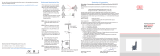
WDS-Z60-M, dimensions in mm
(inches),
not to scale
Precautionary Measures
- Do not open the sensor housing.
- Do not pull or loop the measuring wire around unprotected parts of the
body.
- Do not pull the measuring wire over range.
> Danger of injury
- Do not damage the measuring wire.
- Do not oil or grease the measuring wire.
- Do not bend the measuring wire.
- Do not pull the measuring wire at an angle.
- Do not allow to loop the measuring wire around objects.
- Do not let the measuring wire rewind without control (snap back).
- Fix the measuring wire to the target when wound up only.
Sensor Assembly
- Series Z60: 2x M4 screws DIN 931
- Series P96: 4x M6 screws DIN 931 and 2 groove stones
- Series P115: 4x M6 screws DIN 931 and 2 groove stones
- Series P200: 4x M8 screws DIN 912 and 4 groove stones
The sensor does not have to be oriented in a special way.
Choose the installation position so that damage and soiling of the measu-
ring wire is avoided.
Proper Environment
- Protection class of sensor: IP 65
- Operating temperature: -20 to +80 °C (-4 to +176 °F)
- Storage temperature: -40 to +80 °C (-40 to +176 °F)
- Humidity: 5 - 95 % (non-condensing)
- Ambient pressure: atmospheric pressure
- Vibration: according to IEC 68-2-6
- Mechanical shock: according to IEC 68-2-27
35 (1.38)
25 (.98)
5
(.20)
76 (2.99)
52 (2.05)
ø58 (2.38)
25 (.98)
2 x ø4.3
23 (.91)
7.5
(.30)
10
(.39)
10
(.39)
10.5
(.41)
12.5
(.49)
55.5 (2.19) for encoder
with synchro flange
68.5 (2.70) for encoder with clamping flange
M4
2x M4
28 (1.10)
96 (3.78)
70 (2.76)
96 (3.78)
set screw
M4
81.7 (3.22)
56 (2.20)
ø58 (2.28)
ø50 (1.97)
4x M4x6
36 (1.42)
2x slot nuts
ø13 (.51)
ø10
(.39)
ø13
(.51)
4
(.16)
WDS-P96-M, dimensions in mm
(inches),
not to scale
Installing the Encoder
Make sure that the measuring wire is always tensioned by the spring
motor in order to prevent it from jumping off the pulley.
Flange Encoder
3x M3x10 DIN 912
Mounting of adapter flange and encoder, Series WDS-Z60
Mount the encoder/adapter flange assembly on the draw-wire mecha-
nism.
Fasten the coupling and the encoder shaft with the supplied hexagon
socket screw. Press the supplied cap into the opening in the adapter
flange housing.
i
Make sure that the encoder shaft is not rotated during installation!
Follow the installation instructions issued by the manufacturer of the
encoder.
3xM4 screws DIN7985
with serrated lock washers
Coupler Rotex GS
with grub screw M3
Elastomer
coupler
4xM4 cylinder screws DIN912,
with serrated lock washers
Rotary
encoder
Synchro flange
Mounting of adapter flange and encoder, Series WDS-Pxxx
*X9771136-A04*
X9771136-A041115GBR

Declaration of incorporation
Declaration of incorporation according to the EC Machinery Directive 2006/42/
EC, Annex II B
Manufacturer and authorized representative for the compilation of the relevant
technical documents
MICRO-EPSILON MESSTECHNIK GmbH & Co. KG
Königbacher Straße 15, 94496 Ortenburg / Germany
hereby declares that the machine designated below, as a result of its manner of
design, construction as well as version that has been placed on the market - to
the extent possible in the scope of delivery - corresponds to the relevant, funda-
mental health and safety requirements of the EC Machinery Directive, including
the valid changes at the time of this declaration.
Model: wiresensor
Type designation: WDS-xxx, WPS-xxx
The following fundamental health and safety requirements in accordance with
Annex I of the above-named directive are applied and maintained:
- No. 1.1.2. Principles of safety integration
- No. 1.7.3. Marking of machinery
- No. 1.7.4. Instructions
Furthermore, the compliance with the following standards is explained, including
the valid changes at the time of this declaration:
- EN ISO 13857 Safety of machinery - Safety distances to prevent hazard
zones being reached by upper and lower limbs
- EN 60204-1: 2006/A1: 2009 Safety of machinery - Electrical equipment of
machines - Part 1: General requirements
- DIN EN 61326-1: 2013
- DIN EN 61326-2-3: 2013
Moreover, we declare that the relevant technical documentation for this partly
completed machinery has been created in accordance with part B of Annex VII,
and that we shall be obligated to deliver these upon the request of the market
surveillance authorities.
The described partly completed machinery is intended for installation in a
production line.
The commissioning of this partly completed machinery shall be prohibited until
the partly completed machinery has been installed in a machine that complies
with the provision of the EC Machinery Directive and for which an EC Declara-
tion of Conformity in accordance with Annex II A is available
.
Ortenburg, October 8th 2015 Dr. Thomas Wisspeintner
Managing Director
Wire Guide and Fastening
If the measuring wire has to be extracted from the sensor to guide the wire resp.
to fix it to the target
- the sensor may not be held by another person
- the measuring wire may not be further extracted but only to the specified
measuring range
- the surroundings of the sensor have to be protected against snapping of the
measuring wire
Fix the measuring wire to the
target using a M4 threaded bolt
or eyelet.
Fed the measuring wire per-
pendicularly from the sensor
housing.
Misalignment is only permissible up to
3 degrees.
Dragging of the measuring wire on
the inlet hole or other objects leads
to damage and/or snapping of the
measuring wire.
If the measuring wire cannot be fed
vertically out of the housing, it is es-
sential to use a guide pulley (accesso-
ry TR1-WDS or TR3-WDS).
Keep the measuring wire in
an area, where it cannot be
snagged or otherwise violated.
max. 3 °
Wire outlet 0 °
±3 ° tolerancy
Wire fastening and misalignment
50 (1.97)
ø30
(1.18 dia)
approx. 144 (approx. 5.67 )
115
(4.53)
Hole circle ø42
±
0.1
(1.65 dia
±
0.1)
4x Screw
M4x6 DIN 912
4x serrated lock
washer DIN 6798A
36
(1.42)
60
(2.36)
2x Groove stone
2x Locking screw M4
4x Fixing holes M4
A
4 (1.42)
2.8
(0.11)
1
(0.04)
21.2
(0.83)
B
ø58
(2.28 dia.)
A
115
(4.53)
3x
ø4.3 (0.17 dia.)
after 120°
ø20.2
(0.8 dia.)
10.5±0.5
(0.41)±0.5
4 (0.16)
ø6H7
(0.24 dia.)
+0.012
0
ø
50
(1.97 dia.)
+0.05
0
Detail A
+0.05
0
+0.012
0
79.5 (3.13)
4 x M4
ø20.2
ø30
(1.18)
3x
ø4.3
ø42
(1.65)
ø58 (2.28)
ø50 (1.97)
25.7 (1.01)
200 (7.87)
B
A
WDS-P115-M, dimensions in mm (inches), not to scale
WDS-P200-M, dimensions in mm (inches), not to
scale
Measuring range A B
5000 28 (1.10) 82.5 (3.25)
7500 37 (1.46) 105.5 (4.15)
10000 44.5 (1.75) 148.5 (5.85)
15000 61 (2.40) 180.5 (7.11)
Measuring range A B
30000 268 (10.6) 75 (2.95)
40000 300 (11.8) 95 (3.74)
50000 333.5 (13.1) 95 (3.74)
Operation and Maintenance
Do not grease or oil the measuring wire, the wire drum, the spring motor.
Observe the notes on wire guiding during operation.
Imperfect wire guiding can lead to increased wear and premature defects.
We advise against attempting to do repairs because of the danger of injury and
improper handling. The warranty and all liability claims are null and void if the
device is manipulated by unauthorised persons.
Repairs are to be made exclusively by MICRO-EPSILON.
For further information, please refer to the online documentation.
You will find the latest version at: www.micro-epsilon.com/link/wire > “Draw-wire
sensor mechanics for mounting encoders“.
/