Page is loading ...

WPS - x - MK30
WPS - x - MK46
WPS - x - MK60
WPS - x - MK77
WPS - x - MK88
WPS - x - MK120
Instruction Manual
wireSENSOR, WPS

Declaration of Incorporation
Declaration of incorporation according to the EC Machinery Directive 2006/42/EC, Annex II B
The manufacturer and person authorized to compile the relevant technical documents
MICRO-EPSILON MESSTECHNIK
GmbH & Co. KG
Königbacher Straße 15
94496 Ortenburg / Germany
hereby declare that the machine designated below complies with the relevant fundamental health and safety requirements of the EC
Machinery Directive, including modifications to it applicable at the time of this declaration, based on its design and construction and in
the version put on the market by us – to the extent that the scope of supply allows.
Machine design: Draw-wire sensor (mechanics and models with potentiometer output)
Type designation: WDS-xxx, WPS-xxx
The following fundamental health and safety requirements according to Annex I of the directive specified above have been applied
and complied with:
- No. 1.1.2. Principles of safety integration
- No. 1.7.3. Marking of machinery
- No. 1.7.4. Operating instructions

Furthermore, we declare compliance with the following directives and standards including the modifications applicable at the time this
declaration is made:
- Directive 2006/42/EC (machinery)
EN ISO 13857: 2008 Safety of machinery - Safety distances to prevent hazard zones being reached by upper and lower limbs
EN 60204-1: 2006 + EN 60204-1: 2006/A1: 2009 Safety of machinery - Electrical equipment of machines - Part 1: General re-
quirements
- Directive 2011/65/EU (RoHS)
EN 50581: 2012 Technical documentation for the assessment of electrical and electronic devices with respect to the restriction of
hazardous substances
We also declare that the special technical documentation for this partially completed machine has been created in accordance with
Annex VII, Part B, and commit ourselves to disclose this to the market surveillance authorities upon request.
The commissioning of these partially completed machines is prohibited until the partially completed machine(s) has/have been
installed in a machine that meets the requirements of the EC Machinery Directive and for which an EU Declaration of Conformity ac-
cording to Annex II, Part A exists.
Ortenburg, May 22th 2019 Dr. Thomas Wisspeintner
Managing Director
Fax +49 (0) 8542 / 168-90 www.micro-epsilon.com

wireSENSOR, WPS

wireSENSOR, WPS
Contents
1. Safety ........................................................................................................................................ 7
1.1 Symbols Used ................................................................................................................................................. 7
1.2 Warnings .......................................................................................................................................................... 7
1.3 Notes on CE Marking ...................................................................................................................................... 9
1.4 Intended Use ................................................................................................................................................. 10
1.5 Proper Environment ....................................................................................................................................... 10
1.6 Foreseeable Misuse ....................................................................................................................................... 10
2. Functional Principle, Technical Data ..................................................................................... 11
2.1 Functional Principle ....................................................................................................................................... 11
2.2 Structure ........................................................................................................................................................ 11
2.3 Technical Data MK30 ..................................................................................................................................... 12
2.4 Technical Data MK46 ..................................................................................................................................... 13
2.5 Technical Data MK77 ..................................................................................................................................... 14
2.6 Technical Data MK60 ..................................................................................................................................... 15
2.7 Technical Data MK88 ..................................................................................................................................... 16
2.8 Technical Data MK120 ................................................................................................................................... 17
3. Delivery ................................................................................................................................... 18
3.1 Unpacking, Included in Delivery.................................................................................................................... 18
3.2 Storage .......................................................................................................................................................... 18
4. Installation and Assembly ...................................................................................................... 19
4.1 Precautionary Measures ................................................................................................................................ 19
4.2 Sensor Mounting ........................................................................................................................................... 19
4.3 Wire Guide and Fastening ............................................................................................................................. 29
4.4 Output Specifications Analog ........................................................................................................................ 30
4.4.1 Potentiometer Output ................................................................................................................... 30
4.4.2 Voltage Output .............................................................................................................................. 31
4.4.3 Current Output .............................................................................................................................. 32
4.5 Output Specifications Incremental Encoder ................................................................................................. 33
4.5.1 Signal Output ................................................................................................................................ 33
4.5.2 Pin Assignment ............................................................................................................................. 34

wireSENSOR, WPS
5. Operation ................................................................................................................................ 36
6. Operation and Maintenance .................................................................................................. 36
7. Liability for Material Defects .................................................................................................. 36
8. Service, Repair ....................................................................................................................... 37
9. Decommissioning, Disposal .................................................................................................. 37
Appendix

Page 7
Safety
wireSENSOR, WPS
1. Safety
System operation assumes knowledge of the operating instructions.
1.1 Symbols Used
The following symbols are used in these operating instructions:
Indicates a hazardous situation which, if not avoided, may result in minor or mode-
rate injury.
Indicates a situation that may result in property damage if not avoided.
Indicates a user action.
i
Indicates a tip for users.
1.2 Warnings
Do not open the sensor housing.
> Risk of injury from pre-tensioned spring motor
Do not let the measuring wire rewind without control (snap back).
> Risk of injury from whiplash effect of the wire with assembly bolts/clips
> Destruction of wire and/or of sensor
Do not pull or loop the measuring wire around unprotected parts of the body.
> Risk of injury
Connect the power supply in accordance with the safety regulations for electrical equipment.
> Risk of injury
> Damage to or destruction of the sensor safety

Page 8
Safety
wireSENSOR, WPS
Do not pull the measuring wire over measuring range.
> Destruction of the measuring wire and/or the sensor
Do not let the power supply exceed the specified limits.
> Damage to or destruction of the sensor
Avoid banging and knocking the sensor
> Damage to or destruction of the sensor

Page 9
Safety
wireSENSOR, WPS
1.3 Notes on CE Marking
For WPS draw-wire displacement sensors with voltage, current, digital or encoder outputs, the
EU Directives 2014/30/EU, 2011/65/EU shall apply. In addition, the Machinery Directive is taken into consider-
ation (2006/42/EC).
These sensors carry the CE mark and satisfy the requirements of the EU Directives cited and the European
harmonized standards (EN) listed therein.
The EU Declaration of Conformity is available to the responsible authorities at:
MICRO-EPSILON MESSTECHNIK
GmbH & Co. KG
Königbacher Straße 15
94496 Ortenburg / Germany
Draw-wire displacement sensors with potentiometer output are devices (components) which cannot be oper-
ated autonomously and do not carry a CE mark. For WPS draw-wire displacement sensors with potentiome-
ter output, the directives 2006/42/EC and 2011/65/EU shall apply. Therefore, an EU Declaration of Conformity
is not issued according to EMC law and the Machinery Directive. The Declaration of Incorporation shall apply.
Sources: EMVG (Electromagnetic Compatibility of Equipment law), guidelines on the application of Directive
2014/35/EU, Directive 2006/42/EC.

Page 10
Safety
wireSENSOR, WPS
1.4 Intended Use
- Draw wire sensors are used for
distance or displacement measuring
position determination of components or moving machine parts.
- The sensors must only be operated within the limits specified in the technical data, see Chap. 2..
- Draw wire sensors must be used in such a way that no persons are endangered or machines and other
material goods are damaged in the event of malfunction or total failure of the sensor.
- Take additional precautions for safety and damage prevention in case of safety-related applications.
1.5 Proper Environment
- Protection class for sensor: IP 20
1
IP 65 (MK60, MK88, MK120)
- Operating temperature: -20 °C to +80 °C (-4 to +176 °F)
- Storage temperature: -40 °C to +80 °C (-40 to +176 °F)
- Humidity: 5 - 95 % (non-condensing)
- Ambient pressure: Atmospheric pressure
i
Note the slight power dissipation of the potentiometer above +40°C (+104 °F)! (-0.15 W/10 K)!
1.6 Foreseeable Misuse
Do not further extract the measuring wire but only to the specified measuring range. This may lead to dam-
age of the measuring wire and also to uncontrollable snapping of the measuring wire. Danger of injury.
Make sure the sensor is not held by another person when the measuring wire is extracted. Danger of snap-
ping and injury.
1) For models with potentiometer. For models with encoder depends on encoder type.

Page 11
Functional Principle, Technical Data
wireSENSOR, WPS
2. Functional Principle, Technical Data
2.1 Functional Principle
With the wire principle, a linear motion is transformed into a change in resistance by a rotation.
A measuring wire made of highly flexible stainless steel wires is wound onto a drum with the aid of a long life
spring motor.
The winding drum is coupled axially with a
• multi-turn potentiometer (Type WPS-...-MKxx-...-P/U/I) respectively with an
• encoder (Type WPS-...-MKxx-E).
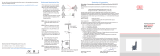
Fig. 1 Draw-wire sensor with potentiometer
2.2 Structure
The draw wire principle is used in the housing design MK30, MK46, MK77, MK60 , MK88 and MK120 with dif-
ferent measuring lengths from 50 to 7500 mm (1.69 to 295.2 in).
Two versions of the electrical connection are possible:
- Potentiometer output (resistance divider)
- Incremental encoder (with integral electronics, HTL or TTL output)

Page 12
Functional Principle, Technical Data
wireSENSOR, WPS
2.3 Technical Data MK30
Model WPS-50
MK30
WPS-150
MK30
WPS-250
MK30
WPS-500
MK30
WPS-750
MK30
Output type
1
P P/E/E830
Measuring range mm 50 150 250 500 750
Linearity (FSO)
P50 (C) ±0.5 % 0.25 mm - - - -
P25 (W) ±0.25 % - - - 1.25 mm 1.87 mm
P25 (H) ±0.25 % - 0.375 mm 0.625 mm - -
P10 (H) ±0.1 % - - 0.25 mm 0.5 mm 0.75 mm
E/E830 ±0.05 % - - - 0.25 mm 0.375 mm
Resolution
W - 0.1 mm 0.1 mm 0.15 mm 0.2 mm
C/H quasi infinite
E/E830
10 pulses per mm with measuring range 500 mm
6.7 pulses per mm with measuring range 750 mm
Sensor element Potentiometer or incremental encoder
Operating temperature °C/ °F -20 ... +80 (-4 ... +176 °F)
Material
Housing Plastics
Wire Stainless steel with polyamid sheath (wire)
Wire diameter mm 0.36
Wire mounting Wire clip
Sensor mounting Mounting holes and mounting grooves
Wire retraction force (min) N Approximately 1
Wire extension force (max) N Approximately 2.5
Protection class
DIN EN60529
P IP 20
E/E830 Depends on sensor design
Electrical connection
P Soldering tags
E/E830 Depends on sensor design
Weight
P g 45
E/E830 g 80
C = conductive plastic potentiometer E/E830 = incremental encoder W = wire potentiometer
H = hybrid potentiometer P = potentiometer FSO = Full Scale Output
1) Specifications for output P, U, I and E/E830, see Chap. 4.4, see Chap. 4.5
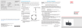
Uncontrolled retraction
of the measuring wire is
incorrect!
> Danger of injury
from whiplash effect
of the wire with as-
sembly bolts/clips
> Destruction of wire
and/or of sensor.

Page 13
Functional Principle, Technical Data
wireSENSOR, WPS
2.4 Technical Data MK46
Model WPS-1000 MK46 WPS-1250 MK46 WPS-1250 MK46
Output type
1
P P/U/I E/E830
Measuring range mm 1000 1250 1250
Linearity (FSO)
E/E830 ±0.05 % - - ±0.625 mm
W ±0.25 % ±2.5 mm ±3.12 mm -
H ±0.1 % ±1 mm ±1.2 mm -
Resolution
W 0.3 mm 0,4 mm -
H quasi infinite
E/E830 4 pulses per mm
Sensor element Potentiometer or incremental encoder
Operating temperature °C/ °F -20 ... +80 (-4 ... +176 °F)
Material
Housing Plastics
Wire Stainless steel with polyamid sheath (wire)
Wire diameter mm 0.36
Wire mounting wire clip
Sensor mounting Mounting holes and mounting grooves
Wire retraction force (min) N 1 0.9 1
Wire extension force (max) N 1.6 1.5 1.4
Protection class IP 20 IP 20 Depends on type
Electrical connection Solder tags Cable radial
Wire acceleration m/s² 75 70 75
Weight (with cable) g 80 80 120
E/E830 = incremental encoder W = wire potentiometer H = hybrid potentiometer
P = Potentiometer FSO = Full Scale Output
1) Specifications for output P, U, I and E/E830, see Chap. 4.4, see Chap. 4.5
Uncontrolled retraction
of the measuring wire is
incorrect!
> Danger of injury
from whiplash effect
of the wire with as-
sembly bolts/clips
> Destruction of wire
and/or of sensor.

Page 14
Functional Principle, Technical Data
wireSENSOR, WPS
2.5 Technical Data MK77
Model WPS-2100 MK77-
P25
WPS-2100 MK77-
CR-P25
WPS-2100 MK77-
E/E830
Output type
1
P E/E830
Measuring range mm 2100
Linearity (FSO) ±0.25 % ±0.05 %
Resolution 0.55 mm 0.43 mm
Sensor element Wire potentiometer or incremental encoder
Operating temperature °C/ °F -20 ... +80 (-4 ... +176 °F)
Material
Housing Plastics
Wire Stainless steel with polyamid sheath (wire)
Wire diameter mm 0.45
Wire mounting wire clip
Sensor mounting Mounting holes and mounting grooves
Wire retraction force (min) N 3.5
Wire extension force (max) N 5
Protection class IP 20 IP 54
Electrical connection Solder tags Cable radial, 1.5 m Cable radial, 2 m
Wire acceleration m/s² 5 5 5
Weight (with cable) g 200 225 270
E/E830 = Incremental encoder P = Potentiometer
FSO = Full Scale Output
1) Specifications for output P, U, I and E/E830, see Chap. 4.4, see Chap. 4.5
Uncontrolled retraction
of the measuring wire is
incorrect!
> Danger of injury
from whiplash effect
of the wire with as-
sembly bolts/clips
> Destruction of wire
and/or of sensor.

Page 15
Functional Principle, Technical Data
wireSENSOR, WPS
2.6 Technical Data MK60
Model WPS-1500-MK60 WPS-2400-MK60-CR
Output type
1
P/U/I TTL01 TTL02
Signals - A, B, O A, /A, B, /B, O
Measuring range mm 1500 2400
Linearity (FSO) ±0.15 % FSO ±0.05 % FSO
Resolution/Sensibility Quasi infinite 6.83 pulses/mm
Sensor element Hybrid potentiometer Incremental encoder
Operating temperature °C -20 ... +80
Material
Housing Plastic, PBT GF20
Wire Coated polamide stainless steel (ø 0.45 mm)
Wire diameter mm 0.45
Wire mounting Wire clip
Sensor mounting Mounting holes on the sensor housing
Wire retraction force (min) N 1
Wire extension force (max) N 8
Protection class IP 65
Electrical connection Cable radial, 1 m
Wire acceleration m/s² 5
Weight (with cable) g 290
P = Potentiometer U = Voltage I = Current
TTL01/ TTL02 = Incremental encoder
FSO = Full Scale Output
1) Specifications for output P, U, I and E/E830, see Chap. 4.4, see Chap. 4.5

Page 16
Functional Principle, Technical Data
wireSENSOR, WPS
2.7 Technical Data MK88
Model WPS-2300 MK88 WPS-3500 MK88 WPS-5000 MK88
Output type
1
P/U/I
Measuring range mm 2300 3500 5000
Linearity (FSO) ±0.15 % ±0.3 % ±0.4 %
Resolution/sensitivity Quasi infinite
Sensor element Potentiometer
Temperature range °C -20 ... +80
Material
Housing Plastic, PA 6 GF 30
Wire Coated polyamid stainless steel
Protection
cap
Aluminum
Wire diameter mm ø 0.45 (0.45 dia.)
Wire mounting Wire clip
Sensor mounting Mounting holes / mounting grooves
Wire retraction force (min) N 4
Wire extension force (max) N 9
Protection class IP 65
Electrical connection Cable radial, 1 m
Wire acceleration (max) Approximately 7 g
Weight (with cable) g 400 - 430
P = potentiometer U = voltage I = current
FSO = Full Scale Output
1) Specifications for output P, U, I and E/E830, see Chap. 4.4, see Chap. 4.5

Page 17
Functional Principle, Technical Data
wireSENSOR, WPS
2.8 Technical Data MK120
Model WPS-3000
MK120
WPS-5000
MK120
WPS-7500
MK120
Output type
1
P, U, I
Measuring range mm 3000 5000 7500
Linearity FSO 0.15 0.15 0.15
Resolution Quasi infinitely
Sensor element Hybrid potentiometer
Operating temperature °C/ °F -20 ... +80 (-4 ... +176 °F)
Material
Housing Plastics PA6
Wire 0,45 mm encapsulated
Wire diameter mm 0.45
Wire mounting Wire clip
Sensor mounting Mounting holes
Wire retraction force (min) N 5.5 5 7
Wire extension force (max) N 8 8 13
Protection class IP 65
Electrical connection Built-in cable, radial, 1 m long
Wire acceleration m/s² 25 25 15
Weight (with cable) kg 0.75 0.75 0.9
P = potentiometer U = voltage I = current
FSO = Full scale Output
1) Specifications for output P, U, I and E/E830, see Chap. 4.4, see Chap. 4.5
Uncontrolled retraction
of the measuring wire is
incorrect!
> Danger of injury
from whiplash effect
of the wire with as-
sembly bolts/clips
> Destruction of wire
and/or of sensor.

Page 18
Delivery
wireSENSOR, WPS
3. Delivery
3.1 Unpacking, Included in Delivery
Do not unpack the sensor by pulling the wire or wire bolt / clip.
Ensure that the goods are forwarded in such a way that no damage can occur.
Check the delivery for completeness and shipping damage immediately after unpacking.
If there is damage or parts are missing, immediately contact the manufacturer or supplier.
i
Remove shipping protection of measuring wire by qualified personnel only and immediately before
mounting.
3.2 Storage
Store only with the transport protection in place. This prevents the measuring wire being pulled out and ac-
cidental is snapping back.
- Storage temperature: -40 °C to +80 °C (-40 to +176 °F)
- Humidity: 5 - 95 % (non-condensing)
- Atmospheric pressure

Page 19
Installation and Assembly
wireSENSOR, WPS
4. Installation and Assembly
4.1 Precautionary Measures
Do not pull the measuring wire over range.
> Damage to or destruction of the sensor is possible
Do not damage the measuring wire.
Do not oil or grease the measuring wire.
Do not bend the measuring wire.
Do not pull the measuring wire at an angle.
Do not allow to loop the measuring wire around objects.
Fix the sensor with drawn in measuring wire to the target.
Do not loop the measuring wire around parts of the body.
4.2 Sensor Mounting
Model Screws Mounting clamp
MK30 3 x M2.5 yes
MK46 3 x M2.5 yes
MK77 3 x M3 yes
MK60 3 x M3 no
MK88 3 x M4 yes
MK120 3 x M6 no
The sensor does not have to be oriented in a special way.
Choose the installation position so that damage and soiling of the measuring wire is avoided.
Prefer an installation position with measuring wire outlet facing downwards if possible.
This prevents liquids penetrating the measuring wire outlet.
i
Do not let snap the measuring wire!
No warranty by damage through snapping.
Uncontrolled retraction
of the measuring wire is
incorrect!
> Danger of injury
from whiplash effect
of the wire with as-
sembly bolts/clips
> Destruction of wire
and/or of sensor.
Save the wire during
installation work.

Page 20
Installation and Assembly
wireSENSOR, WPS
P: ø 23 (.91)
ø 3
(.11 DIA)
2
(.07)
E: ø 24 (.94)
10.5
(.41)
21 (.83)
E: 40 (1.57)
P: 42.5 (1.67)
42 (1.65)
50 (1.97)
23.5 (.93)
30 (1.18)
Mounting
hole 3x ø 2.7
(ø .10)
Mounting clamp
with screw M3
6
(.23)
23.5 (.93)
30 (1.18) 15.5 (.61)
for MB 50/150: 8 (.31)
for MB 250/500: 8 (.31)
for MB 750:12 (.47)
ø 4.5
(.18)
ø 9
(.35)
Potentiometer/
incremental
encoder
Mechanics
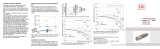
Fig. 2 Dimensional drawing WPS- ... -MK30 with potentiometer or encoder, dimensions in mm (inches), not to
scale
/