Page is loading ...

920-0443-00 Rev. C
Page 1 of 4
Installation and Operation Instructions
XTP SERIES LIGHT HEADS
Single and Split Colors
Introduction:
CODE3 XTP series LED heads are compact and versatile high intensity
directional LED warning lights suitable for mounting anywhere on a vehicle.
Colorless until illuminated, these discrete LED heads feature a high degree
of environmental and vibration protection.
Additional benets include low current draw, a long and maintenance free
service life with reliable solid-state operation. LED heads can be controlled
by conventional switches or relays and can also be synchronized to ash
with other compatible CODE3 synchronizing LED products.
IMPORTANT! Read all instructions before installing and using. Installer: This manual must be delivered to the end user.
WARNING!
Failure to install or use this product according to manufacturers recommendations may result in property damage, serious injury, and/or
death to those you are seeking to protect!
1. Proper installation combined with operator training in the use, care, and maintenance of emergency warning devices are essential to
ensure the safety of emergency personnel and the public.
2. Emergency warning devices often require high electrical voltages and/or currents. Exercise caution when working with live electrical
connections.
3. This product must be properly grounded. Inadequate grounding and/or shorting of electrical connections can cause high current arcing,
which can cause personal injury and/or severe vehicle damage, including re.
4. Proper placement and installation is vital to the performance of this warning device. Install this product so that output performance of the
system is maximized and the controls are placed within convenient reach of the operator so that s/he can operate the system without losing
eye contact with the roadway.
5. It is the responsibility of the vehicle operator to ensure daily that all features of this product work correctly. In use, the vehicle operator
should ensure the projection of the warning signal is not blocked by vehicle components (i.e., open trunks or compartment doors), people,
vehicles or other obstructions.
6. The use of this or any other warning device does not ensure all drivers can or will observe or react to an emergency warning signal. Never
take the right-of-way for granted. It is your responsibility to be sure you can proceed safely before entering an intersection, drive against
trafc, respond at a high rate of speed, or walk on or around trafc lanes.
7. This equipment is intended for use by authorized personnel only. The user is responsible for understanding and obeying all laws regarding
emergency warning devices. Therefore, the user should check all applicable city, state, and federal laws and regulations. The manufacturer
assumes no liability for any loss resulting from the use of this warning device.
Do not install and/or operate this safety product unless you have read and understand the safety information contained in
this manual.
Contents:
Specications.........01
Installation and Mounting.........02
Wiring Instructions.........02
Programming Flash Patterns....02-04
Troubleshooting.........04
Replacement Parts and Accessories.........04
Warranty.........04
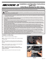
1 Light Head
2 Screws
1 Installation Guide
1 Mounting Gasket
1 Bezel
Specications:
Light Head Model XTP3 XTP4 XTP6
Input Voltage 12-24VDC 12-24VDC 12-24VDC
Work Current 0.5A Max @ DC12V or 24V 1.0A Max @ DC12V or 24V 1.0A Max @ DC12V or 24V
Physical H x W x L 0.62 in x 1.39 in x 3.65 in
1.58 cm x 3.53 cm x 9.28 cm
0.62 in x 1.39 in x 4.72 in
1.58 cm x 3.53 cm x 11.98 cm
0.62 in x 1.39 in x 6.21 in
1.58 cm x 3.53 cm x 15.78 cm
Weight 0.088 lb (0.04 Kg) 0.127 lb (0.06 Kg) 0.160 lb (0.07 Kg)
AvailableSingle Colors Red, Blue, Amber, White, Green Red, Blue, Amber, White, Green Red, Blue, Amber, White, Green
Available Split Dual
Colors
N/A Amb/Wht, Blue/Amb, Blue/Wht, Red/Amb,
Red/Blue, Red/Wht
Amb/Wht, Blue/Amb, Blue/Wht, Red/Amb,
Red/Blue, Red/Wht
Operation Environment:
Ambient Temperature: -40 to 77°C(-40 to 170°F)
Package Contains:

920-0443-00 Rev. C
Page 2 of 4
PATTERN
GROUP
RED WIRE
FLASH PATTERN
SYNC
Complies
with
0
1-Default Cycle Flash no
1
2 Single Flash 75FPM sim. Phase1 yes SC
3 Single Flash 75FPM sim. Phase2 yes SC
2
4 Single Flash 120FPM sim. Phase1 yes S
5 Single Flash 120FPM sim. Phase2 yes S
3
6 Double Flash 75FPM sim. Phase1 yes SC
7 Double Flash 75FPM sim. Phase2 yes SC
4
8 Double Flash 120FPM sim. Phase1 yes Blue, Amb SE1 - Red SE2
9 Double Flash 120FPM sim. Phase2 yes Blue, Amb SE1 - Red SE2
5
10 Quad Flash 75FPM sim. Phase1 yes SC
11 Quad Flash 75FPM sim. Phase2 yes SC
Pattern Select Operation:
Notes on Synchronizing and Phase (Sync Ph):
Notes on Choosing Flash Patterns:
Notes on Dim Control:
The light head intensity may be reduced if necessay. The Blue wire when connected to positive will reduce the intensity to 25% for SAE patterns. Light intensity for ECE
patterns will reduce to 55%.
NOTE: The blue wire must be disconnected from any voltage when not activating DIM nor changing ash patterns.
The light head ash pattern may be changed by touching the Blue wire to ground for the following intervals (while the light head is ashing):
NOTE: The blue wire must be disconnected from any voltage when not activating DIM nor changing ash patterns.
- When the light head signal becomes steady, disconnect the Blue wire and the ash pattern will increment by one pattern.
- When the light head signal becomes steady, then goes off, disconnect the Blue wire and the ash pattern will decrement by one pattern.
- When the light head signal becomes steady, then goes off, then becomes steady again, disconnect the Blue wire and the ash pattern will reset to the factory default
pattern.
- When the light head signal becomes steady, then goes off, then becomes steady again, then goes off again, disconnect the Blue wire and the ash pattern will become
set to the steady burn mode.
Wiring Instructions:
RED: Positive, (5A fuse required)
WHITE: Positive, (5A fuse required)
BLACK: Negative
BLUE: Pattern select to negative -- Dim control to positive
YELLOW: Synchronized Function (Up to 32 units can be Synchronized)
Caution! When drilling into any vehicle surface,
make sure that the area is free from any electrical wires,
fuel lines, vehicle upholstery, etc. that could be damaged.
Installation and Mounting:
Important! This unit is a safety device, and it must be
connected to its own separate, fused power point to as-
sure its continued operation should any other electrical
accessory fail.
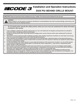
To mount the light head, use the bezel as a template to mark the mounting holes. The
supplied self-tapping #6 x 0.75” screws typically use 0.125” diameter holes but this may vary
depending on the type of material and the thickness being tapped. Provide a minimum 0.50”
diameter hole for the wires. Grommet the hole if possible and seal with RTV sealant.
It is important to note:
The light head has a small round hole covered with vent membrane that must face
downward when mounting the light head.
A variety of ash patterns may be chosen for the light head. The Single and Split Dual Color light heads are split vertically as separate lighted areas that may be chosen
to operate alternately. The Split Dual Color version has different colors for the left side versus the right side to allow for patterns that ash right-left using various color
combinations. The XTP3 does not have this feature.
A separate ash pattern may be assigned for the power wires red, white, or both connected together and the pattern operated depending which wire or wires are
energized. Power the wire (or wires) then use the pattern select blue wire (touch to ground) to select the chosen ash pattern from the list below. The XTP3 can only be
assigned one ash pattern.
Note: The split dual color light heads have a separate ash pattern list.
See the legend at the top of the pattern lists for compliance with various standards.
(Up to 32 light heads can be Synchronized by connecting their yellow wires).
When the yellow wires of the light heads are connected together, the group with Ph1 ash patterns will ash simultaneously. If the light heads in the second group are set
to Ph2 ash patterns, they will ash alternately with the rst group. To simplify the set-up of a synchronized installation, the following process is recommended:
1. Before connecting the yellow wires together, choose the desired ash pattern for each light head. The patterns chosen must have the same ash rate for all light
heads intended to be synchronized. (By denition a 75fpm light head will not sync with at 120fpm light head) To avoid confusion set each light head in-
dividually to the chosen ash pattern using the blue pattern select wire. Ph1 light heads will alternate with Ph2 light heads and simultaneously with all other light
heads set to Ph1. Ph2 light heads ash simultaneously with all other light heads set to Ph2. It is also strongly recommended that the same style of ash pattern
be used on all heads to produce the most effective warning pattern.
2. Connect the yellow synchronization wires together and check that the light heads are ashing in a synchronized manner as expected. If a pattern for one light head
appears to be wrong, keep the yellow wire connected and use the blue pattern select wire to cycle forward or backward for that individual light head until the cor-
rect pattern is selected. Once that is completed verify the light head is synchoronized correctly.
Flash Patterns XTP3:
For patterns that meet SAE J595 Class1 requirements for Red, Blue, Amber, and White, see S in chart below!
For patterns that meet California Title 13 Class B requirements for Red, Blue, and Amber, see C in chart below!
For patterns that meet ECE65 Class1 Cat X (night only) requirements for Blue, Amber, see E1 in chart below!
For patterns that meet ECE65 Class2 Cat X (day & night) requirements for Red, see E2 in chart below!
PATTERN
GROUP
RED WIRE
FLASH PATTERN
SYNC
Complies
with
6
12 Quad Flash 150FPM sim. Phase1 yes S
13 Quad Flash 150FPM sim. Phase2 yes S
7
14 Triple 75FPM sim. Phase1 yes SC
15 Triple 75FPM sim. Phase2 yes SC
8
16 Quint Flash 150FPM sim. Phase1 yes S
17 Quint Flash 150FPM sim. Phase2 yes S
9 18 Modulation No
10 19 2 Double Flash, 2 Triple Flash No
11 20 4 Single Flash, 2 Quad Flash No
12 21 Steady Burn No

920-0443-00 Rev. C
Page 3 of 4
PATTERN
GROUP
RED
WIRE
WHITE
WIRE
RED &
WHITE
WIRE
FLASH PATTERN
SYNC
Complies
with
0 1-Default 1-Default 1-Default Cycle Flash no
1
2 2 2 Single Flash 75FPM sim. Phase1 yes SC
3 3 3 Single Flash 75FPM sim. Phase2 yes SC
4 4 4 Single Flash 75FPM Alt. yes S
2
5 5 5 Single Flash 120FPM sim. Phase1 yes S
6 6 6 Single Flash 120FPM sim. Phase2 yes S
7 7 7 Single Flash 120FPM Alt. yes S
3
8 8 8 Double Flash 75FPM sim. Phase1 yes SC
9 9 9 Double Flash 75FPM sim. Phase2 yes SC
10 10 10 Double Flash 75FPM Alt. yes S
4
11 11 11 Double Flash 120FPM sim. Phase1 yes SE2
12 12 12 Double Flash 120FPM sim. Phase2 yes SE2
13 13 13 Double Flash 120FPM Alt. yes S
5
14 14 14 Quad Flash 75FPM sim. Phase1 yes SC
15 15 15 Quad Flash 75FPM sim. Phase2 yes SC
16 16 16 Quad Flash 75FPM Alt. yes S
6
17 17 17 Quad Flash 150FPM sim. Phase1 yes S
18 18 18 Quad Flash 150FPM sim. Phase2 yes S
19 19 19 Quad Flash 150FPM Alt yes S
7
20 20 20 Triple 75FPM sim. Phase1 yes SC
21 21 21 Triple 75FPM sim. Phase2 yes SC
22 22 22 Triple 75FPM Alt. yes S
8
23 23 23 Quint Flash 150FPM sim. Phase1 yes S
24 24 24 Quint Flash 150FPM sim. Phase2 yes S
25 25 25 Quint Flash 150FPM Alt. yes S
9 26 26 26 Steady - Single No
10 27 27 27 Modulation No
11 28 28 28 2 Double Flash, 2 Triple Flash No
12 29 29 29 4 Single Flash, 2 Quad Flash No
13 30 30 30 Steady Burn No
Flash Patterns XTP4 and XTP6 - Single Color:
PATTERN
GROUP
RED
WIRE
WHITE
WIRE
RED &
WHITE
WIRE
FLASH PATTERN
SYNC
Cmplies
with
0 1-Default 1-Default 1-Default Cycle Flash no
1
2 2 2 Single Flash 75FPM Alt. Phase1 yes S
3 3 3 Single Flash 75FPM Alt. Phase2 yes S
2
4 4 4 Single Flash 120FPM Alt. Phase1 yes S
5 5 5 Single Flash 120FPM Alt. Phase2 yes S
3
6 6 6 Double Flash 75FPM Alt. Phase1 yes S
7 7 7 Double Flash 75FPM Alt. Phase2 yes S
4
8 8 8 Double Flash 120FPM Alt. Phase1 yes S
9 9 9 Double Flash 120FPM Alt. Phase2 yes S
5
10 10 10 Quad Flash 75FPM Alt. Phase1 yes S
11 11 11 Quad Flash 75FPM Alt. Phase2 yes S
6
12 12 12 Quad Flash 150FPM Alt. Phase1 yes S
13 13 13 Quad Flash 150FPM Alt. Phase2 yes S
7
14 14 14 Triple 75FPM Alt. Phase1 yes S
15 15 15 Triple 75FPM Alt. Phase2 yes S
8
16 16 16 Quint Flash 150FPM Alt. Phase1 yes S
17 17 17 Quint Flash 150FPM Alt. Phase2 yes S
9
18 18 18 Steady - Single No
10 19 19 19 Modulation No
11 20 20 20 2 Double Flash, 2 Triple Flash Alt. No
12 21 21 21 4 Single Flash, 2 Quad Flash Alt. No
13 22 22 22 Steady Burn No
Flash Patterns XTP4 and XTP6 - Split Dual Colors:
Flash Patterns XTP4 and XTP6 versions:
For patterns that meet SAE J595 Class1 requirements for Red, Blue, Amber, and White, see S in chart below!
For patterns that meet California Title 13 Class B requirements for Red, Blue, and Amber, see C in chart below!
For patterns that meet ECE65 Class2 Cat X (day & night) requirements for Red, Blue, Amber, see E2 in chart below!

920-0443-00 Rev. C
Page 4 of 4
Product Returns:
If a product must be returned for repair or replacement*, please contact our factory to obtain a Return Goods Authorization Number (RGA number)
before you ship the product to Code 3®, Inc. Write the RGA number clearly on the package near the mailing label. Be sure you use sufcient
packing materials to avoid damage to the product being returned while in transit.
*Code 3®, Inc. reserves the right to repair or replace at its discretion. Code 3®, Inc. assumes no responsibility or liability for expenses incurred for the removal and /or reinstallation of products requiring service and/or repair.; nor for the packaging, handling,
and shipping: nor for the handling of products returned to sender after the service has been rendered.
Manufacturer Limited Warranty Policy:
Manufacturer warrants that on the date of purchase this product will conform to Manufacturer’s specications for this product (which are avail-
able from the Manufacturer upon request). This Limited Warranty extends for Sixty (60) months from the date of purchase.
DAMAGE TO PARTS OR PRODUCTS RESULTING FROM TAMPERING, ACCIDENT, ABUSE, MISUSE, NEGLIGENCE, UNAPPROVED MODIFICA-
TIONS, FIRE OR OTHER HAZARD; IMPROPER INSTALLATION OR OPERATION; OR NOT BEING MAINTAINED IN ACCORDANCE WITH THE
MAINTENANCE PROCEDURES SET FORTH IN MANUFACTURER’S INSTALLATION AND OPERATING INSTRUCTIONS VOIDS THIS LIMITED WAR-
RANTY.
Exclusion of Other Warranties:
MANUFACTURER MAKES NO OTHER WARRANTIES, EXPRESS OR IMPLIED. THE IMPLIED WARRANTIES FOR MERCHANTABILITY, QUALITY
OR FITNESS FOR A PARTICULAR PURPOSE, OR ARISING FROM A COURSE OF DEALING, USAGE OR TRADE PRACTICE ARE HEREBY EX-
CLUDED AND SHALL NOT APPLY TO THE PRODUCT AND ARE HEREBY DISCLAIMED, EXCEPT TO THE EXTENT PROHIBITED BY APPLICABLE
LAW. ORAL STATEMENTS OR REPRESENTATIONS ABOUT THE PRODUCT DO NOT CONSTITUTE WARRANTIES.
Remedies and Limitation of Liability:
MANUFACTURER’S SOLE LIABILITY AND BUYER’S EXCLUSIVE REMEDY IN CONTRACT, TORT (INCLUDING NEGLIGENCE), OR UNDER ANY
OTHER THEORY AGAINST MANUFACTURER REGARDING THE PRODUCT AND ITS USE SHALL BE, AT MANUFACTURER’S DISCRETION, THE
REPLACEMENT OR REPAIR OF THE PRODUCT, OR THE REFUND OF THE PURCHASE PRICE PAID BY BUYER FOR NON-CONFORMING PROD-
UCT. IN NO EVENT SHALL MANUFACTURER’S LIABILITY ARISING OUT OF THIS LIMITED WARRANTY OR ANY OTHER CLAIM RELATED TO
THE MANUFACTURER’S PRODUCTS EXCEED THE AMOUNT PAID FOR THE PRODUCT BY BUYER AT THE TIME OF THE ORIGINAL PURCHASE.
IN NO EVENT SHALL MANUFACTURER BE LIABLE FOR LOST PROFITS, THE COST OF SUBSTITUTE EQUIPMENT OR LABOR, PROPERTY
DAMAGE, OR OTHER SPECIAL, CONSEQUENTIAL, OR INCIDENTAL DAMAGES BASED UPON ANY CLAIM FOR BREACH OF CONTRACT, IM-
PROPER INSTALLATION, NEGLIGENCE, OR OTHER CLAIM, EVEN IF MANUFACTURER OR A MANUFACTURER’S REPRESENTATIVE HAS BEEN
ADVISED OF THE POSSIBILITY OF SUCH DAMAGES. MANUFACTURER SHALL HAVE NO FURTHER OBLIGATION OR LIABILITY WITH RESPECT
TO THE PRODUCT OR ITS SALE, OPERATION AND USE, AND MANUFACTURER NEITHER ASSUMES NOR AUTHORIZES THE ASSUMPTION OF
ANY OTHER OBLIGATION OR LIABILITY IN CONNECTION WITH SUCH PRODUCT.
This Limited Warranty denes specic legal rights. You may have other legal rights which vary from jurisdiction to jurisdiction. Some jurisdic-
tions do not allow the exclusion or limitation of incidental or consequential damages.
Replacement Parts and Accessories:
Troubleshooting:
Part/Accs XTP3 XTP4 XTP6
Bezel Black Plastic T51874 T51875 T51876
Bezel Chrome Plastic 250-0425-00 250-0427-00 250-0429-00
Mtg Grommet Rubber T51890 T51891 T51892
Mtg Gasket Foam T51886 T51887 T51888
The XTP series light head has been thoroughly factory tested. If any of the the device functions fail, please check the following:
1. Be sure the power source is activated, then check all connections both positive and ground at the light head (to assure no open or shorted circuits).
2. Permanently connecting the Blue programming wire to ground will disable the light head, no matter what the programmed ash pattern.
3. If the Dim function does not operate, verify the Blue wire is connected to positive.
4. If the sync function is not being used and the light head is functioning erratically, verify the Yellow wire is not connected to positive or ground.
10986 North Warson Road
St. Louis, MO 63114
Customer Service
(314) 426-2700
www.code3esg.com
An ECCO SAFETY GROUP™ Company
www.eccosafetygroup.com
/