Page is loading ...

1
1 2
2
25
22
18
1
6
10
3
1
TEST
6
30
R1
120
60
50
40
30
15
10
A
16
10
5
2
1
30
15
TEST
2000
1200
600
200
40
5
25
22
18
1
6
10
3
1
TEST
6
30
R1
2000
1200
600
200
40
C
D
2000
1200
600
200
40
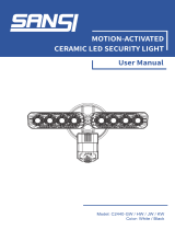
3. Inbetriebnahme / Einstellungen
Follow-up time for light control
The time can be set infinitely variably at between
1 and 30 minutes.
Symbol TEST: Test mode (Every movement switches on
the light for a period of 1 second, switching it off for a
period of 2 seconds after that regardless of the level of
brightness.)
Twilight-switch for light control (relay 1)
The switch-on value for the light can be set at between 10
and 2000 Lux. Using the rotary control, the luminance set
points can be set as desired.
Symbol
: Night-time operation
Symbol
: Daytime/Night-time operation
Orientation lighting
This rotary controller serves to determine the working time
of the orientation lighting (fixed to 20 %).
“ON” for permanent orientation lighting.
“OFF” for deactiviation of orientation lighting.
Installation and Operating Instruction for B.E.G. - Occupancy detectors PD2-M-DALI/DSI-SM/-FC and
PD4-M-DALI/DSI-SM/-FC
A circular opening of diameter 68 –
70mm must be produced in the ceiling.
Having connected up the cables in accor-
dance with regulations, the detector is
inserted into the opening as shown in the
drawing opposite and fixed into position
with the assistance of the spring clips.
2a. Installation of the LUXOMAT
®
PD2/PD4-M-
DALI/DSI-SM
2b.
Installation of the LUXOMAT
®
PD2/ PD4-M-DALI/DSI
-FC
The detector must be in stalled on a solid and level surface.
The circular cover ring must be removed prior to assembly.
To do this, twist the lens (C) of the PD4 or (D) of the PD2
anticlockwise through approximately 5° and lift off.
Having connected up the wires in accordance with regula-
tions, secure the detector with 2 screws. After installation
replace the lens and lock (turn clockwise). Mains to be
connected.
Unlocking device
Lock device
4. Settings carried out using remote control (optional)
Remote control LUXOMAT
®
IR-PD-DALI
1. Check Battery:
open battery compartment by pressing the plastic
springs together and removing the battery-holder.
2. IMPORTANT
Please pay attention, that the setting is Potentio-
meter 1 at “TEST” and Potentiometer 2 not at
“SUN”. All values which have been programmed
using the remote control will be deleted in the
event of power failure in the position “TEST/
SUN”. Please switch Potentiometer 2 over to
“MOON” or any other value.
Caution:
Settings with remote control supersede the settings
by courtesy of potentiometers.
LUXOMAT
®
PD2/PD4-M-DALI/DSI
1b. Mounting preparations
Work on the 230V mains supply
may only be carried out by quali-
fied professionals or by instructed
persons under the direction and
supervision of qualified skilled elec-
trical personnel in accordance with
electrotechnical regulations.
Disconnect supply before installing!
When in Master/Slave mode of
operation, the Master-appliance
must always be installed at the
location where there is least
daylight.
Switching between DSI and DALI program
Factory setting DSI, press 1x DALI, press 2x DSI/DALI
(Toggle-function)
Luminance set point for constant light regulation
+ / – small steps
+
/
–
big steps
Dimming
The following approach will prove useful when setting a
command value (example workplace): Place a luxmeter flat
on the desk, then, using the remote control IR-PD-DALI, adjust
the light up or down by pressing the keys max or min until
the desired command value which best suits your require-
ments has been reached.
Automatic reading in the current light value
as new luminance set point
Individual light value 2 - 2500Lux
Follow-up time (relay and channel 1)
1 up to 30min.
Orientation lighting and its follow-up time
OFF button: No orientation light
Grey button: Programming the switch-off delay time
On button:
Orientation light is permanently activated.
Note: During the orientation light phase, the constant light reg-
ulation is also active: if there is sufficient brightness, dimming
occurs < 2 V and, if applicable, the lighting is switched off.
Preset/user mode => (see page 2, point 6)
Fully automatic/semi automatic mode => (see page 2, point 5)
Semi automatic: green LED,
Fully automatic: red LED on for approx. 3sec.
Resetting when open
All values which have been programmed using the remote
control IR-PD-DALI are deleted, and those values which have
been set by potentiometer are activated.
Lock device
Test mode
Reset to deactivate
Resetting when closed
The lighting relay is switched off, i.e.
opened and the follow-up times reset.
Permanent protection against sabotage
This function blocks the unit permanently (green LED is
illuminated). This operating mode can only be activated
during the period of 5 seconds after pressing the “lock“
button. This status will only permit actuating the function
“Light on/Light off”.
The procedure for leaving this mode is as follows:
1. Switch off the current
2. Apply current for 31 - 59 seconds
3. Switch of the current again
4. Apply current
5. Open detector
Light on/off
The light will remain switched on/off for as long as move-
ments are detected in the areas of coverage. Once the last
movement has been detected, the light will remain on for
the duration of the follow-up time as per setting.
The appliance will then return independently to the mode
selected (Fully or Semi-automatic).
Option:
Wall bracket for remote control
IR-PD-DALI
The product enters an initial 60-second
self-test cycle, when the supply is first
connected. The occupancy detector is
ready for operation.
2c. Self test cycle
1a. Features
*
For connection of up to 25 lamps
in FC-version and up to 12 lamps
SM-version
* Suitable for dimmable electronic
ballasts and control modules
* DALI output
* Constant light control
* Manual switching /dimming
* Semi or completely automatic
operation
*
Luminance (brightness) set point,
switch-off delay time for LIGHT and
orientation-light adjustable
* Sensor and power sections in one
housing
* Infrared remote control
max
50
Lux
1500
Lux
ON
OFF
close
open
max
50
Lux
1500
Lux
ON
OFF
max
50
Lux
1500
Lux
ON
OFF
max
50
Lux
1500
Lux
ON
OFF
max
50
Lux
1500
Lux
ON
OFF
max
50
Lux
1500
Lux
ON
OFF
max
50
Lux
1500
Lux
ON
OFF
max
50
Lux
1500
Lux
ON
OFF
20 %
max
50
Lux
1500
Lux
ON
OFF
+
–
DS I /
DA L I
25
22
18
1
6
10
3
1
TEST
6
30
R1
120
60
50
40
30
15
10
A
16
10
5
2
1
30
15
TEST
2000
1200
600
200
40
5
60
5
10
30
50
ON
OFF
GB

max
50
Lux
1500
Lux
ON
OFF
max
50
Lux
1500
Lux
ON
OFF
max
50
Lux
1500
Lux
ON
OFF
Sensor and power supply in one case
Power supply: 230 V~ +6 %/-10 %
Power consumption: < 1W
Ambient temperature: -25°C to +50°C
Degree of protection/class:
PD2-M-DALI/DSI-SM IP20, with
accessory IP54, PD2/PD4-M-DALI/DSI-FC IP20 / II
Settings:
locally and by remote control
Light values - IR-PD-DALI:
50 - 1500 Lux
Extension of the detection area:
with Slaves
Area of coverage:
circular 360°
Range of coverage Ø H 2.50m / T=18°C:
PD2-M-DALI/DSI seated 2.50m / tangential 10m / radial 6m
PD4-M-DALI/DSI seated 6.40 m / tangential 24 m / radial 8m
Recommended height for mounting:
2 - 3 m
Light measurement: mixed light, daylight + artificial light
Lux values-Potentiometer:
10 - 2000 Lux
• DALI-Output
digital BUS control wire, 2-core, no polarity (broadcast only)
Max. no. of series-connected electronic ballasts:
PD2/PD4-M-DALI/DSI-DE up to 25
PD2/PD4-M-DALI/DSI-AP up to 12
Time-settings:
1 - 30min. / test
Dimensions HxØ [mm]
SM FC
PD2-M-DALI/DSI 50x 98 84,5 x 80
PD4-M-DALI/DSI 76 x 101 97x 103
Technical data PD2/PD4-Slave
Electrical data same as above, but just one channel for
signaling motion detection.
Declaration of Conformity:
The product complies with
the low voltage recommendation 2006/95/EC and the
EMV recommendation 2004/108/EC.
12.
Technical data
PD2/PD4-M-DALI/DSI
9. Wiring diagram
10.
PD2/PD4-M-DALI/DSI
- Connections
Type SM FC
PD2-M-DALI/DSI-Master 92280 92258
PD4-M-DALI/DSI-Master 92279 92275
PD2-Slave 92152 92166
PD4-Slave 92142 92254
LUXOMAT
®
Remote control:
IR-PD-DALI (incl. wall bracket) 92094
Accessory:
BSK Ball basket guard 92199
Wall bracket for remote control as replacement
92100
SM-Socket IP54 92161
11. Article / Part nr. / Accessory
MAN 5632 – 141209-4
Connections PD2/PD4-M-DALI/DSI-SM
13. LED-functional indicators, fault-finding
The functional indicators in the case of the LUXOMAT
®
PD2/PD4-M-DALI/DSI-MASTER (red and green LED‘s)
Red LED indicating self-checking mode (over a period
of 60 seconds following mains-supply lock-on)
Flashing at intervals of 1 second
EEPROM/memory empty
Flashing rapidly
EEPROM/memory contains information
Red LED as an indicator of status
Flashing irregularly
Movements are detected within the area of coverage
Flashing regularly
Detector identifies bright, light off
(dependent upon operating mode)
Not illuminated
Detector identifies dark, light on
(dependent upon operating mode)
Flashing extremely rapidly
Too bright / Too dark / Undefined
Red LED as an acknowledgement of receipt for
commands from the remote control
Illuminated for 2 seconds
Signal validly received
Illuminated for 0.5 seconds
Not-accepted command, detector blocked
Flashing extremely rapidly
Not-accepted command, occurs, for example, when
an attempt is made to input twilight-value are too
bright or too dark
Green LED as an acknowledgement of receipt for
commands from the remote control
Lights up for 3 seconds
Semi automatic or user signal correctly received
Green LED as an indicator of status (only for status
“Permanent protection against sabotage”)
Flashing irregularly
Movement are detected within the area of coverage
Flashing regularly
Detector identifies bright, light off
(dependent upon operating mode)
Not illuminated
Detector identifies dark, light on
(dependent upon operating mode)
lluminated for 2 seconds
Signal validly received
(dependent upon operating mode)
PD4-M-DALI/DSI
PD2-M-DALI/DSI
1
2
quer zum Melder gehen
frontal zum Melder gehen
Unterkriechschutz
walking across
walking towards
seated
Connections PD2/PD4-M-DALI/DSI-FC
–
+
NLS R
SLAVE
DALI
–
+
N LSR
SLAVE
DALI
L N
8. Range of Coverage
6. Manual Dimming - Preset / User
(for IR-PD-DALI functions see page 1)
You can dim manually by pressing the pushbutton for
a long time (> 2 sec). When the button is released,
the current dimming value is retained. Upon renewed
dimming, the dimming direction is reversed.
PRESET – the luminance set point is set during start-up
operation by the installer and remains unchanged.
The luminance set- point congured through manual
dimming is only applied for the time being.
Caution:
The constant light regulation is now deactivated!
The currently set articial light is retained independent
of the ambient/daylight brightness!
After switching off and then back on, the originally set
luminance set-point is reset = constant light regulation
is activated.
USER - can only be activated via the remote control!
The luminance set-point is changed upon each manual
dimming and re-adjusted by the user (Conformation
through relay clicking!).
The constant light regulation remains activated!
5. Fully / Semi automatic mode
(for IR-PD-DALI functions see page 1)
Fully automatic operation
In this operating mode, the lighting switches automati-
cally on and off for increased comfort, depending on
presence and brightness.
Semiautomatic operation
(Semiautomatic can only be activated via the remote
control!)
In this operating condition, in order to gain increased
savings, the lighting is energized only after being manu-
ally switched on.
Switch-off takes place automatically.
The semiautomatic mode basically behaves like the fully
automatic one. However, the difference is that switching-
on must always be carried out manually!
As many (closer-contact) buttons as desired can be wired
in parallel on the “S” button input (ON/OFF Dimm).
7. Manual Switching
You can switch the lighting on and off manually by
pressing the pushbutton for a short time. It will stay on or
off as long as people are detected plus the congured
follow up time.
L
N
Terminal connection for MASTER-/SLAVE-operation
N – N L – L R – R
MASTER
SLAVE
230V
~
DA DA
DALI-EVG 1
230V
~
DA DA
DALI-EVG 2-25
PD2/PD4-M-DALI/DSI-FC = up to 25 / PD2/PD4-M-DALI/
DSI-SM = up to 12 electronic ballasts (EB) are connectable.
R S N L DALI
T5 und T8
uorescent
lamps
24 m
8 m
6.40 m
24 m
360°
2.50 m
2
1
10 m
6 m
2.50 m
10 m
360°
2.50 m
2
1
/