Page is loading ...

special applications, refer to NFPA 72 or the System Smoke Detector Applica-
tion Guide, available from Silent Knight.
WIRING GUIDE
All wiring must be installed in compliance with the National Electrical Code,
applicable local codes, and any special requirements of the Authority Having
Jurisdiction. Proper wire gauges should be used. The installation wires should
be color-coded to limit wiring mistakes and ease system troubleshooting.
Improper connections will prevent a system from responding properly in the
event of a fire.
Remove power from the communication line before installing sensors.
1. Wire the sensor base (supplied separately) per the base wiring diagram.
(See Figure 1.)
2. Set the desired address on the sensor address switches. (See Figure 2.)
3. Install the sensor into the sensor base. Push the sensor into the base
while turning it clockwise to secure it in place.
4. After all sensors have been installed, apply power to the control panel
and activate the communication line.
5. Test the sensor(s) as described in the TESTING section of this manual.
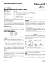
FIGURE 1. WIRING DIAGRAM
2
3
1
2
3
3
1
2
1
(–)
(+)
+-
UL LISTED COMPATIBLE
CONTROL PANEL
CLASS A OPTIONAL WIRING
REMOTE
ANNUNCIATOR
(–)
(+)
C0129-04
CAUTION
Do not loop wire under terminal 1 or 2. Break wire run to provide supervision
of connections.
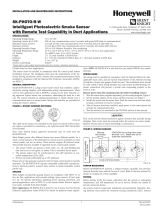
FIGURE 2. ROTARY ADDRESS SWITCHES
TENS ONES
9
10
11
12
13
14
15
8
7
6
5
4
3
2
1
0
9
8
7
6
5
4
3
2
1
0
C0162-00
SPECIFICATIONS
Operating Voltage Range: 15 to 32 VDC
Operating Current @ 24 VDC: 200 uA (one communication every 5 seconds with green LED blink on communication)
Maximum Alarm Current: 2 mA @ 24 VDC (one communication every 5 seconds with red LED solid on)
Maximum Current: 4.5 mA @ 24 VDC (one communication every 5 seconds with amber LED solid on)
Operating Humidity Range: 15% to 90% Relative Humidity, Non-condensing
Operating Temperature Range: 32°F to 100°F (0°C to 38°C)
Air Velocity: 0 to 4000 ft./min. (0 to 1219.2 m/min.)
Height: 2.7˝ (69 mm) installed in B200S series sounder base
Diameter: 6.875˝ (175 mm) installed in B200S series sounder bases
Weight: 3.4 oz. (95 g)
Isolator Load Rating: 0.0063*
*Please refer to your isolator base/module manual for isolator calculation instructions.
UL 2075 listed for Carbon Monoxide
UL 268 listed for Open Air Protection
UL 521 listed for Heat Detectors
This sensor must be installed in compliance with the control panel sys-
tem installation manual. For local audible indication of a fire and/or
carbon monoxide alarm, it is recommended to install the multi-criteria
carbon monoxide (CO) and smoke sensors into a B200S series sounder
base. If a local audible device is not used, care should be taken to de-
velop a proper response plan. The installation must meet the require-
ments of the Authority Having Jurisdiction (AHJ). Sensors offer maximum
performance when installed in compliance with the National Fire Protec-
tion Association (NFPA); see NFPA 72 and NFPA 720. For a complete list
of compatible bases, refer to the Base/Sensor Cross Reference Chart at
systemsensor.com.
GENERAL DESCRIPTION DOES THIS SUPPORT CLIP MODE
Model SK-FIRE-CO-W is a plug-in type multi-criteria smoke sensor that offers
a photoelectric sensing chamber combined with a carbon monoxide (CO) sen-
sor, 135°F (57.2°C) fixed temperature heat detector and infrared (IR) sensors,
as well as a carbon monoxide detector. The SK-FIRE-CO-W also transmits an
alarm signal due to heat (135°F/57.2°C) per UL 521.
All sensors transmit an analog representation of smoke and/or carbon monox-
ide density over a communication line to a control panel. Rotary dial switches
are provided for setting the sensor’s address. (See Figure 2.)
Two LEDs on the sensor are controlled by the panel to indicate sensor status.
An output is provided for connection to an optional remote LED annunciator
(P/N RA100Z).
Silent Knight panels offer different features sets across different models. As a
result, certain features of the photoelectric sensors may be available on some
control panels, but not on others.
The multi-criteria CO and smoke sensors only support SK protocol systems.
The possible features available in the multi-criteria CO and smoke sensors, if
supported by the control unit are:
1. The sensor’s LEDs can operate in three ways—on, off, and blinking—and
they can be set to red, green, or amber. This is controlled by the panel.
2. The remote output may be synchronized to the LED operation or con-
trolled independent of the LEDs.
3. Devices are point addressable up to 159 addresses.
Please refer to the operation manual for the UL listed control panel for specific
operation. The photoelectric sensors require compatible addressable com-
munications to function properly. Connect these sensors to listed-compatible
control panels only.
SPACING
Silent Knight recommends spacing sensors in compliance with NFPA 72. In
low air flow applications with smooth ceilings, space sensors 30 feet apart
(9.1 m). For specific information regarding sensor spacing, placement, and
I56-6602-000
INSTALLATION AND MAINTENANCE INSTRUCTIONS
SK-FIRE-CO-W
Multi-Criteria CO and Smoke Sensor
12 Clintonville Road, Northford, CT 06472-1610
Phone: 203-484-7161 Fax: 203-484-7118
www.silentknight.com
1 I56-6602-000
2/21/2019

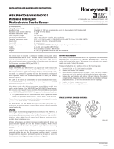
FIGURE 3. FEATURES OF THE FIRE/CO DETECTOR
Base Alignment Notch
Infrared
Light
Pipe
CO Test Point
Magnet Test Point
Thermistors
Infrared
Light
Pipe
LEDs
C2043-00
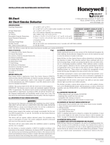
FIGURE 4. CLEANING THE FIRE/CO DETECTOR
Cover
Removal
Tabs
Sensor Cover
Sensing Chamber
Cover and Screen
Infrared
Light
Pipe
Thermistors
Sensing
Chamber
}
C2044-00
CAUTION
Dust covers provide limited protection against airborne dust particles during
shipping. Dust covers must be removed before the sensors can sense smoke.
Remove sensors prior to heavy remodeling or construction.
TAMPER RESISTANCE
Model SK-FIRE-CO-W includes a tamper-resistant capability that prevents re-
moval from the base without the use of a tool. Refer to the base manual for
details on making use of this capability.
TESTING
Before testing, notify the proper authorities that the system is undergoing
maintenance, and will temporarily be out of service. Disable the system to
prevent unwanted alarms.
All sensors must be tested after installation and periodically thereafter. Test-
ing methods must satisfy the Authority Having Jurisdiction (AHJ). Sensors
offer maximum performance when tested and maintained in compliance with
NFPA 72. Sensitivity readings are available through the FACP. Refer to the
manufac turer’s published instructions for proper use.
The sensor can be tested in the following ways:
A. Functional: Magnet Test (P/N M02-04-01 or M02-09-00)
This sensor can be functionally tested with a test magnet. The test mag-
net electronically simulates smoke in the sensing chamber, testing the
sensor electronics and connections to the control panel.
a. Hold the test magnet in the magnet test area as shown in Figure 3.
b. The sensor should alarm the panel.
Two LEDs on the sensor are controlled by the panel to indicate sensor
status. Coded signals, transmitted from the panel, can cause the LEDs
to blink, latch on, or latch off. Refer to the control panel technical docu-
mentation for sensor LED status operation and expected delay to alarm.
NOTE: The magnet test initiates an approximately 10 minute period
when the detector's signal processing software routines are not active.
B. Smoke Entry
Canned aerosol simulated smoke (canned smoke agent) may be used for
smoke entry testing of the smoke detector.
The multi-criteria CO and smoke sensor uses algorithms to process sig-
nals received from multiple sensors to determine alarm conditions and
reduce false alarms. Therefore, a single burst of canned smoke will not
immediately place the detector into an alarm condition because the de-
tector algorithms correctly determine a burst of canned smoke is not fire.
In order to perform functional testing of the photoelectric sensor, the
device must be placed into test mode. Test mode allows the detector to
isolate the individual sensors for testing. The device can be placed into
test mode through either of the following methods.
a. Put the device into test mode by holding a test magnet in the magnet
test area as shown in Figure 3 for 6-12 seconds.
NOTE: If the magnet is held in place for too long the fire alarm test func-
tion will be triggered. (See Magnet Test, above.) Reset the panel and
proceed with testing the smoke entry portion of the device.
b. Perform smoke entry testing immediately following the magnet test.
The magnet test initiates an approximately 10 minute period when the
detector’s signal processing software routines are not active.
Once in test mode, test the smoke detector using one of the tested and ap-
proved aerosol smoke products. Refer to the manufacturer’s published instruc-
tions for proper use of the canned smoke agent. When used properly, the
canned smoke agent will cause the smoke detector to go into alarm.
Tested and approved aerosol smoke products include:
Manufacturer Model
HSI Fire and Safety 25S, 30S (PURCHECK)
SDi SMOKE CENTURION , SOLOA10,
SMOKESABRE, TRUTEST, SOLO 365
No Climb TESTIFIRE 2000
CAUTION
Canned aerosol simulated smoke (canned smoke agent) formulas will vary
by manufacturer. Misuse or overuse of these products may have long term
adverse effects on the smoke detector. Consult the canned smoke agent manu-
facturer’s published instructions for any further warnings or caution statements.
C. Direct Heat Method (Hair Dryer of 1000-1500 watts)
A hair dryer of 1000-1500 watts should be used to test the thermistors.
Direct the heat toward the thermistor, holding the heat source approxi-
mately 12 inches (30 cm) from the detector in order to avoid damaging
the plastic housing. The detector will reset only after it has had sufficient
time to cool. Make sure both thermistors are tested individually.
D. Multi-Criteria Testing
Testifire® by SDi provides testing of the smoke, heat and CO sensors. Consult
the manufacturer’s published instructions for complete usage instructions.
A sensor that fails any of these tests may need to be cleaned as described
under CLEANING, and retested. When testing is complete, restore the system
to normal operation and notify the proper authorities that the system is back
in operation.
E. Functional Gas Test
NOTE: Check with local codes and the AHJ to determine whether or not
a functional gas test is desired for an installation.
A canned CO testing agent may be used to verify the detector’s ability to
sense CO. Carbon Monoxide alarm thresholds are designed around CO
concentrations over time, as defined in UL standard 2034. Therefore, a
single burst of CO test agent will not immediately place the detector into
an alarm condition. In order to perform functional testing of the CO sen-
sor, the device must be placed into test mode. Test mode eliminates the
time and concentration requirements needed for alarm and allows the
CO sensor to be tested. The device can be placed into test mode through
either of the following methods.
a. Put the device into test mode by holding a test magnet in the magnet
test area as shown in Figure 3 for 6-12 seconds.
NOTE: If the magnet is held in place for too long the fire alarm test func-
tion will be triggered. Reset the panel and proceed with testing the CO
portion of the device.
b. Perform functional gas entry testing immediately following the magnet
test. The magnet test initiates an approximately 10 minute period when
the detector's signal processing software routines are not active.
Once in test mode, test the CO sensor using a tested and approved
canned CO testing agent. A tested and approved canned CO testing agent
is Solo detector testers model C6 CO Detector Tester available from SDi.
Complete the CO sensor testing as follows:
Spray a UL approved CO agent into the top of the detector near the CO
sensor opening for at least 1 second. CO sensor opening is indicated by
2 I56-6602-000
2/21/2019

a triangle on the sensor cover. (See Figure 3.) Use the applicator straw
included with the CO agent to more efficiently direct the CO into the
detection cell during testing.
The detector will go into alarm if gas entry is successful. It may take up
to 1 minute for the device to alarm. Once the detector is in alarm allow
5 minutes for the CO to clear and exit the detector.
The detector will automatically enable the signal processing after 10 min-
utes.
Testing the detector will activate the alarm relay and send a signal to
the panel.
CLEANING
Before removing the detector, notify the proper authorities that the smoke
detector system is undergoing maintenance and will be temporarily out of
service. Disable the zone or system undergoing maintenance to prevent un-
wanted alarms.
1. Remove the sensor to be cleaned from the system.
2. Remove the sensor cover by pressing firmly on each of the four removal
tabs that hold the cover in place. (See Figure 4.)
3. Vacuum the screen carefully without removing it. If further cleaning is
required continue with Step 4, otherwise skip to Step 7.
4. Remove the chamber cover/screen assembly by pulling it straight out.
5. Use a vacuum cleaner or compressed air to remove dust and debris from
the sensing chamber.
6. Reinstall the chamber cover/screen assembly by aligning the arrows on
the top with the two round-top posts on the sensing chamber, and gently
pressing it until it fits securely.
7. Replace the cover using the LEDs to align the cover and then gently
pushing it until it locks into place. NOTE: Make sure that the thermistors
do not become bent under the cover.
8. Reinstall the detector.
9. Test the detector as described in TESTING.
10. Reconnect disabled circuits.
11. Notify the proper authorities that the system is back on line.
ABOUT CARBON MONOXIDE DETECTORS
CAUTION
CAUTION: This carbon monoxide detector is designed for indoor use only.
Do not expose to rain or moisture. Do not knock or drop the detector. The
detector will not protect against the risk of carbon monoxide poisoning if
not properly wired. The detector will only indicate the presence of carbon
monoxide gas at the sensor. Carbon monoxide gas may be present in other
areas.
This carbon monoxide detector is NOT:
• Designed to detect any gas other than carbon monoxide
• To be seen as a substitute for the proper servicing of fuel-burning appli-
ances or the sweeping of chimneys.
• To be used on an intermittent basis, or as a portable alarm for the spill-
age of combustion products from fuel-burning appliances or chimneys.
Carbon monoxide gas is a highly poisonous gas which is released when fuels
are burnt. It is invisible, has no smell and is therefore impossible to detect
with the human senses. Under normal conditions in a room where fuel burn-
ing appliances are well maintained and correctly ventilated, the amount of
carbon monoxide released into the room by appliances should not be danger-
ous.
SYMPTOMS OF CARBON MONOXIDE POISONING
Carbon monoxide bonds to the hemoglobin in the blood and reduces the
amount of oxygen being circulated in the body. The following symptoms are
examples taken from NFPA 72 and 720. They represent approximate values
for healthy adults:
Concentration (ppm CO) Symptoms
200 Mild headache
after 2-3 hours of exposure
400 Headache and nausea
after 1-2 hours of exposure
800 Headache, nausea, and dizziness
after 45 minutes of exposure;
collapse and unconsciousness
after 2 hours of exposure
Many causes of reported carbon monoxide poisoning indicate that while vic-
tims are aware that they are not well, they become so disoriented that they
are unable to save themselves by either exiting the building or calling for
assistance.
Also young children and pets may be the first to be affected.
Per UL standard 2075, the SK-FIRE-CO-W has been tested to the sensitivity
limits defined in UL standard 2034.
ALARM THRESHOLDS ARE AS FOLLOWS:
Parts Per Million Detector response time, min.
70 ±5ppm 60-240
150 ±5ppm 10-50
400 ±10ppm 4-15
What to do if the carbon monoxide detector goes into alarm:
Immediately move to a spot where fresh air is available, preferably out-
doors.
IMPORTANT: This detector should be tested and maintained regularly fol-
lowing National Fire Protection Association (NFPA) 720 requirements.
CO SENSOR LIFETIME
The CO cell has an expected lifetime of approximately ten years. The detector
is programmed to signal the approach of end of this lifetime to the control
panel. The CO cell is not a field replaceable component. The smoke sensor
will continue to operate using other sensing elements (photoelectric, heat and
infrared) even though the CO cell is no longer operational. The CO detector
will not operate once the CO cell has reached its end of life.
SPECIAL NOTE REGARDING SMOKE DETECTOR GUARDS
Smoke detectors are not to be used with detector guards unless the combina-
tion has been evaluated and found suitable for that purpose.
3 I56-6602-000
2/21/2019

SPECIAL APPLICATION
When configured at the fire alarm control panel, this detector is capable of op-
erating in a special application mode such that it has a higher sensitivity than
is normally allowed by UL 268 for areas where early warning is important. In
this mode, the detector does not comply with the Cooking Nuisance Smoke
Test. Detectors (Sampling ports) set to the special application mode are not
suitable for use in areas where cooking appliances may be used. If cooking
appliances are used within the protected space, a normal application detector
or normal application mode must be used for that area.
Special application mode is not for general use and the detector may be more
prone to false alarms if used in unsuitable environments. While no list is
all-inclusive, some examples of unsuitable environments for special applica-
tion mode are areas with airborne particulate or aerosols including sawing,
drilling, and grinding operations, textile or agricultural processing, or areas
with engines that are not vented to the outside. A complete list of aerosol and
particulate sources is available in the Annex of NFPA 72.
Suitable environments for special application mode could include early warn-
ing for hospitals, museums, assisted living and other areas that do not have
airborne particulate or aerosols.
Refer to the fire alarm control panel documentation for information on how to
configure the detector for special application mode.
Silent Knight
®
is a registered trademark of Honeywell International, Inc. Testifire
®
and SOLO
®
are registered trademarks of SDi, LLC.
FCC STATEMENT
This device complies with part 15 of the FCC Rules. Operation is subject to the following two conditions: (1) This device may not cause harmful interference,
and (2) this device must accept any interference received, including interference that may cause undesired operation.
NOTE: This equipment has been tested and found to comply with the limits for a Class B digital device, pursuant to Part 15 of the FCC Rules. These limits
are designed to provide reasonable protection against harmful interference in a residential installation. This equipment generates, uses and can radiate radio
frequency energy and, if not installed and used in accordance with the instructions, may cause harmful interference to radio communications. However, there
is no guarantee that interference will not occur in a particular installation. If this equipment does cause harmful interference to radio or television reception,
which can be determined by turning the equipment off and on, the user is encouraged to try to correct the interference by one or more of the following
measures:
– Reorient or relocate the receiving antenna.
– Increase the separation between the equipment and receiver.
– Connect the equipment into an outlet on a circuit different from that to which the receiver is connected.
– Consult the dealer or an experienced radio/TV technician for help.
Please refer to insert for the Limitations of Fire Alarm Systems
DEVICE AND SYSTEM SECURITY
Before installing this product ensure that the
tamper seal on the packaging is present and
unbroken and the product has not been tampered
with since leaving the factory. Do not install this
product if there are any indications of tampering.
If there are any signs of tampering the product
should be returned to the point of purchase.
It is the responsibility of the system owner to
ensure that all system components, i.e. devices,
panels, wiring etc., are adequately protected to
avoid tampering of the system that could result
in information disclosure, spoofing, and integrity
violation.
4 I56-6602-000
©2019 Silent Knight. 2/21/2019
/