Page is loading ...

THE INFORMATION CONTAINED IN THIS DRAWING IS
THE SOLE PROPERTY OF SYNERGY MFG. ANY
REPRODUCTION IN PART OR WHOLE WITHOUT THE
WRITTEN PERMISSION OF SYNERGY MFG IS
PROHIBITED.
Revisions
Rev.
Description
Date
Approved
A
Initial release per eco 21-039
4/26/2021
KB
JT Rear Adjustable Track Bar
Installation Instructions
Applications:
2019+ Jeep JT Gladiator
TITLE:
JT REAR ADJUSTABLE TRACK BAR
INSTALLATION INSTRUCTIONS
SIZE
DWG NO:
REV
A
8881-01-INST
A
SCALE: N/A
PAGE 1 OF 6

JT REAR ADJUSTABLE TRACK BAR
INSTALLATION INSTRUCTIONS
DOC NO. 8881-01-INST PAGE 2 OF 6
Thank you for purchasing the best aftermarket products available for your vehicle. We strongly feel that the
parts you are about to install should meet or exceed your expectations for performance. Proper assembly is
critical to the performance of these components and the vehicle as a whole. Please take the time to carefully
read these instructions and familiarize yourself with the installation procedure before working on your
vehicle. If you have any questions PLEASE contact Synergy Manufacturing BEFORE beginning
installation. Thanks again for supporting Synergy – enjoy the performance benefits of the best aftermarket
products available for your vehicle!
Synergy Manufacturing
Phone: (805) 242-0397
Email: [email protected]
Modifying or otherwise altering vehicle components may cause the vehicle to handle differently than
originally designed. It is the driver’s responsibility to familiarize themselves with the performance and
handling characteristics of the modified vehicle. Vehicles with larger diameter than stock tires must be
driven carefully and cannot be expected to perform as stock or meet OEM performance with regard to
handling, braking or crash performance. Ensure all replacement components are compatible with vehicle
capacities so as not to overload components, especially tires. It is up to the individual to ensure that the
vehicle and all components are compatible with the intended vehicle use, including load ratings, road
conditions, and driver abilities. Thorough and frequent vehicle inspections are recommended to ensure a
safe and reliable state of readiness, especially after off-highway use.
PARTS LIST
8881-01 JT REAR ADJUSTABLE TRACK BAR
QTY
Part Number
Description
1
888101-PC
JEEP JT REAR ADJ TRACK BAR, POWDERCOATED
1
3622-07-14L-PL
DOUBLE ADJUSTER SLEEVE 7/8 – 14TPI LH
1
4811-01
TRACK BAR DDB JOINT, 1.75OD BUSHING, 7/8-14LH SHANK
1
4327-01
TRACK BAR BUSHING, 1.75OD
1
SSM10-1.5-12-SS
CONE POINT SET SCREW, HIGH HOLD, M10-1.5 X 12MM, 18-8SS
1
N/A
1/2-20 X 1 3/4” HEX BOLT, GRADE 8
1
N/A
1/2-20 TOP LOCK NUT
GENERAL NOTES
• These instructions are also available on our website; www.synergymfg.com. Check the website
before you begin for any updated instructions and additional photos or videos for your reference.
• The installation of this adjustable track bar will allow you to correctly align the rear axle after a
suspension lift kit is installed.
• This track bar is formed to allow fitment of a 37” spare tire in the factory spare tire location.
• The track bar features a double adjuster sleeve which allows you to adjust the length of the track bar
without removing the end of the track bar from the vehicle.
• Replacement bushings are available from Synergy Mfg.

JT REAR ADJUSTABLE TRACK BAR
INSTALLATION INSTRUCTIONS
DOC NO. 8881-01-INST PAGE 3 OF 6
TOOLS REQUIRED
• 21mm and 3/4 inch sockets and wrenches
• 1-1/4 inch wrench or adjustable (Crescent type) wrench
• Torque Wrench
• Tape measure and straight edge
ESTIMATED INSTALLATION TIME
1/2 Hour
INSTALLATION
1. Installation can be done on the ground. There is no need to lift the vehicle off the ground or remove
the wheels and tires. The track bar comes preassembled with all necessary components.
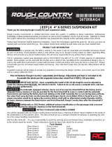
2. Using a 21mm socket, loosen and unbolt the rear track bar from the axle side mount. Support the
track bar so it will not fall when you remove the bolt. Save the stock hardware, it will be re-used.
See Figure 1.
Figure 1. Removing the Track Bar from the Axle End

JT REAR ADJUSTABLE TRACK BAR
INSTALLATION INSTRUCTIONS
DOC NO. 8881-01-INST PAGE 4 OF 6
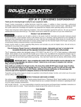
3. Using a 21mm socket, loosen, then unbolt the frame side track bar bolt taking care to once again
support the track bar before you pull the bolt all the way out. Save the stock hardware, it will be re-
used. Completely remove the track bar. See Figure 2.
Figure 2. Removing the Track Bar from the Frame Side
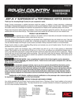
4. Install the Synergy Mfg. track bar by putting the adjustable side in the frame side track bar mount and
reuse the OEM bolt and nut. Make sure the bend in the bar is up and towards the front. The adjuster
forging pinch bolt bungs should be pointing down. See Figure 3.
Figure 3. Installing the Synergy Mfg. Track Bar at the Frame

JT REAR ADJUSTABLE TRACK BAR
INSTALLATION INSTRUCTIONS
DOC NO. 8881-01-INST PAGE 5 OF 6
5. Next, install the non-adjustable side into the axle side mount. Adjust the track bar length with the
adjuster sleeve at the frame end until the track bar bushing bolt hole and the axle mount bolt holes
line up. Make sure the adjuster sleeve end is adjusted by turning the adjuster sleeve and not the
bushing end or track bar itself. The bend in the tube should point up and forward, and the pinch bolt
mount on the other end should point down when done. See Figures 4 and 5. If the bar cannot be
adjusted to make the bolt holes line up, a ratchet strap between the frame and opposing side on the
axle can be used to pull the body whichever way it needs to get the bolt holes to line up.
Figure 4. Installing the Synergy Mfg. Track Bar at the Axle
Figure 5. Correctly Installed Synergy Mfg. Rear Track Bar
6. Torque the track bar bolts to OEM specifications; Axle side bolt and nut – 100 lb-ft, frame side bolt
and nut – 92 lb-ft.

JT REAR ADJUSTABLE TRACK BAR
INSTALLATION INSTRUCTIONS
DOC NO. 8881-01-INST PAGE 6 OF 6
7. With the Jeep on the ground at ride height, use the double adjuster to center the axle under the body
of the Jeep. You can measure from the frame to the tire on each side to get the axle centered, or use a
straightedge from the outside of the tire to the body and measure each side, see Figure 6. Make sure
the adjuster sleeve end is adjusted by turning the adjuster sleeve and not the bushing end or track bar
itself. We recommend rotating the sleeve until one of the slots in the sleeve lines up with the slot in
the track bar. See Figure 7.
Figure 6. and 7. Measuring Side to Side and Adjusting the Track Bar to Center the Axle
8. With a 3/4 inch socket and wrench, tighten the pinch bolt at the double adjuster on the track bar to 90
lb-ft. See Figure 7.
Figure 7. Tightening the Pinch Bolt and Nut
9. Re-check bolt torques after the first 100 miles and again after each off-road trip.
Installation is Complete
Table 1. Jeep JL Rear Track Bar Bolt Torques
Bolted Joint Location
Wrench Size
Torque
Axle Side Track Bar Bolt
21mm
100 lb-ft
Frame Side Track Bar Bolt
21mm
92 lb-ft
Adjuster Pinch Bolt
3/4”
90 lb-ft
/