Page is loading ...

IonPac® CS15
for

IonPac CS15 Document No. 031272-06 Page 1 of 43
PRODUCT MANUAL
for the
IONPAC® CG15 GUARD COLUMN
(2 x 50 mm, P/N 052256)
(4 x 50 mm, P/N 052200)
IONPAC® CS15 ANALYTICAL COLUMN
(2 x 250 mm, P/N 052252)
(4 x 250 mm, P/N 051795)
© Dionex Corporation, 2009
Document No. 031272
Rev. 06
9 April 2009

IonPac CS15 Document No. 031272-06 Page 2 of 43
TABLE OF CONTENTS
SECTION 1 - INTRODUCTION ....................................................................................................... 5
SECTION 2 - COMPARISON OF ION CHROMATOGRAPHY SYSTEMS ................................ 7
SECTION 3 - INSTALLATION ......................................................................................................... 9
3.1 System Requirements ............................................................................................................................................... 9
3.1.1 System Requirements for 2-mm Operation .................................................................................................................. 9
3.1.2 System Requirements for 4-mm Operation .................................................................................................................. 9
3.1.3 System Void Volume .................................................................................................................................................... 9
3.2 Installing the CR-CTC Trap Column for Use with EGC II MSA Cartridge ............................................................ 9
3.3 Installing the Cation Trap Column for Eluent Step Change or Gradient Operation .............................................. 9
3.4 The Injection Loop ................................................................................................................................................... 10
3.4.1 The 2-mm System Injection Loop, 2–15 μL ............................................................................................................... 10
3.4.2 The 4-mm System Injection Loop, 10–50 μL.............................................................................................................. 11
3.5 Sample Concentration .............................................................................................................................................. 11
3.7 Eluent Storage .......................................................................................................................................................... 11
3.8 Cation Self-Regenerating Suppressor Requirements ............................................................................................ 11
3.6 IonPac CG15 Guard Columns ................................................................................................................................. 11
3.9 Cation MicroMembrane Suppressor Requirements .............................................................................................. 12
3.10 Suppressor Caution ................................................................................................................................................ 12
3.11 Using AutoRegen .................................................................................................................................................... 12
3.12 Detector Requirements ........................................................................................................................................... 13
4.3 Chemical Purity Requirements .............................................................................................................................. 14
4.3.1 Deionized Water ........................................................................................................................................................ 14
SECTION 4 - OPERATION ............................................................................................................. 14
4.1 General Operating Conditions ............................................................................................................................... 14
4.2 Operating Precautions ........................................................................................................................................... 14
4.3.2 Inorganic Chemicals .................................................................................................................................................. 14
4.4 Preparation of Eluent Stock Solution Concentrates .............................................................................................. 14
4.4.1 1.0 N (0.5M) Sulfuric Acid Stock Solution ................................................................................................................. 14
4.4.2 1.0 N (1.0 M) Methanesulfonic Acid (MSA) Stock Solution ..................................................................................... 14
4.4.3 Eluent Preparation ..................................................................................................................................................... 15

IonPac CS15 Document No. 031272-06 Page 3 of 43
4.5 Eluents with Solvents .............................................................................................................................................. 16
4.5.1 Making and Using Eluents that Contain Solvents .................................................................................................... 16
SECTION 5 - EXAMPLE APPLICATIONS .................................................................................... 17
5.1 Production Test Chromatogram ............................................................................................................................. 18
5.1.1 Test Chromatogram Comparison ............................................................................................................................... 19
5.2 Isocratic Elution of 6-Cations plus Ethanolamine .................................................................................................. 20
5.3 Isocratic Elution of 6-Cations Plus Morpholine .................................................................................................... 21
5.4 4000:1 Ratio Sodium to Ammonium ....................................................................................................................... 22
5.5 10,000:1 Ratio Ammonium to Sodium .................................................................................................................... 23
5.6 10,000:1 Ratio Potassium to Ammonium ............................................................................................................... 24
5.7 Fast Run Analysis using CS15 and CG15 ............................................................................................................. 25
5.8 Gradient Separation of Alkanolamines .................................................................................................................. 26
5.9 Gradient Elution of Ethylamines using CS15 and CG15 ....................................................................................... 27
SECTION 6 - TROUBLESHOOTING GUIDE ............................................................................... 28
6.1 High Back Pressure ............................................................................................................................................... 29
6.1.1 Finding the Source of High System Pressure ............................................................................................................ 29
6.1.2 Replacing Column Bed Support Assemblies ............................................................................................................. 30
6.2 Preparation of Eluents ............................................................................................................................................ 30
6.3 Contamination ......................................................................................................................................................... 30
6.3.1 A Contaminated Guard or Analytical Column ........................................................................................................... 30
6.3.2 Sample Loop and/or Tubing Contamination ............................................................................................................. 30
6.4 High Background or Noise ..................................................................................................................................... 32
6.5 Suppressor Not Suppressing Properly ................................................................................................................. 33
6.6 Poor Peak Resolution ............................................................................................................................................. 34
6.6.1 Loss of Peak Efficiency throughout the Chromatogram ............................................................................................ 34
6.6.2 Loss of Resolution Throughout the Chromatogram Due to Shortened Retention Times ......................................... 34
6.6.3 Increasing Peak Resolution by Increasing Acid Concentration ................................................................................ 36
6.6.4 Loss of Early Eluting Peak Resolution ...................................................................................................................... 37
6.7 Spurious Peaks ....................................................................................................................................................... 37

IonPac CS15 Document No. 031272-06 Page 4 of 43
APPENDIX A - QUALITY ASSURANCE REPORT ....................................................................... 38
APPENDIX B - COLUMN CARE ................................................................................................... 41
Recommended Operating Pressures ................................................................................................................................ 41
Column Start-Up ................................................................................................................................................................ 41
Column Storage ................................................................................................................................................................. 41
Column Conditioning ......................................................................................................................................................... 41
Column Cleanup ................................................................................................................................................................ 41
Column Cleanup Procedure for Polyvalent Cations and Acid-Soluble Contaminants or Transition Metals ........................ 42
Hydrophobic Cations and Organic Contaminants ............................................................................................................... 42

IonPac CS15 Document No. 031272-06 Page 5 of 43
SECTION 1 - INTRODUCTION
The IonPac® CS15 4-mm (P/N 051795) and 2-mm (P/N 052252) Analytical Columns are designed specifically for the analysis
of alkali metals, alkaline earth metals, and ammonium at extreme concentration ratios. The CS15 and CG15 stationary phase is
functionalized with a crown ether and relatively weak phosphonic and carboxylic acids having a high selectivity for hydronium
ion. The crown ether functionality has a high selectivity for potassium and ammonium which retains potassium at the end of the
run and greatly improves the resolution between sodium and ammonium. The weak carboxylate functional groups require low
ionic strength eluents to isocratically elute both monovalent and divalent cations in a relatively short period of time. The CS15
is solvent-compatible with 100% acetonitrile, 20% tetrahydrofuran or 100% aqueous eluents without loss of performance.
The IonPac CS15 should be used with a CSRS ULTRA P/N 053948 (4-mm), 053949 (2-mm) when operated
with eluents containing organic solvents or when operating at elevated temperatures (40 °C)
DO NOT USE ALCOHOLS
Formation of esters will occur in the column packing. This can significantly reduce the column capacity
for cation exchange.
Do NOT use the IonPac CS15 column with basic eluents
Table 1
IonPac CS15/CG15 Packing Specifications
Column Particle SubstrateaColumn Functional Hydrophobicity
Diameter X-linking Capacity Group
μm % meq/column
CS15 8.5 55 2.8 Crown Ether/ Medium to low
4 x 250 mm Carboxylic/
Phosphonic acid
CG15 8.5 55 0.56 Crown ether/ Medium to low
4 x 50 mm Carboxylic/
Phosphonic acid
CS15 8.5 55 0.7 Crown ether/ Medium to low
2 x 250 mm Carboxylic/
Phosphonic acid
CG15 8.5 55 0.14 Crown ether/ Medium to low
2 x 50 mm Carboxylic/
Phosphonic acid
a macroporous divinylbenzene/ethylvinylbenzene polymer
CAUTION
CAUTION

IonPac CS15 Document No. 031272-06 Page 6 of 43
Table 2
CS15/CG15 Operating Parameters
Standard Maximum
Column Typical Back Pressure Flow Rate Flow Rate
psi (MPa) mL/min mL/min
CS15 4-mm Analytical < 1,350 (9.31) 1.2 3.0
CG15 4-mm Guard < 450 (3.10) 1.2 3.0
CS15 + CG15 4-mm columns < 1,800 (12.41) 1.2 3.0
CS15 2-mm Analytical < 1,350 (9.31) 0.3 0.75
CG15 2-mm Guard < 450 (3.10) 0.3 0.75
CS15 + CG15 2-mm columns < 1,800 (12.41) 0.3 0.75
Read the system manuals. This manual assumes that you are familiar with the installation and operation of the Dionex Ion
Chromatograph (IC). If you do not understand the operation of the system, take the time to familiarize yourself with the various
system components before beginning an analysis.
You may need to make a liquid line fitting. The IonPac CS15 Analytical Column and the IonPac CG15 Guard Column have
10-32 PEEK end fittings for use with ferrule/bolt liquid line fittings. If you have an Ion Chromatograph with Tefzel® liquid lines
having 1/4-28 ThermoFlare fittings, it will be necessary to obtain one or more Tefzel liquid lines with a PEEK bolt and ferrule
fitting on one end and a 1/4-28 ThermoFlare fitting on the other end. See, “Dionex Liquid Line Fittings,” for detailed instructions
on purchasing or making these lines.
Always remember that assistance is available for any problem that may be encountered during the shipment or
operation of Dionex instrumentation and columns through the Dionex North America Technical Call Center at
1-800-DIONEX-0 (1-800-346-6390) or through any of the Dionex Offices listed in, “Dionex Worldwide Offices.”

IonPac CS15 Document No. 031272-06 Page 7 of 43
SECTION 2 - COMPARISON OF ION CHROMATOGRAPHY SYSTEMS
The proper configuration of 2-mm system injection volume, mass loading, system void volume and flow rate is based the
ratio of the 2-mm to 4-mm column cross-sectional area which is a factor of 1/4.
CONFIGURATION 2-mm 4-mm
Eluent Flow Rate 0.30 mL/min 1.2 mL/min
SRS Suppressor CSRS-ULTRA (2-mm)
(P/N 053949)
CSRS-ULTRA (4-mm)
(P/N 053948)
MMS Suppressor CMMS III (2-mm)
(P/N 056753)
Operation without solvents
CMMS III (4-mm)
(P/N 056752)
Operation without solvents
NOTE
Do not run suppressors over 40 °C. If application requires a higher temperature, place suppressor outside of
chromatographic oven.
Regenerant Flow Rate See suppressor manual. See suppressor manual.
Injection Loop 2 - 15 µL
Use the Rheodyne Microinjection
Valve, Model No. 9126 DIONEX P/N
044697) for full loop injections <15
µL.
10-50 µL
System Void Volume Eliminate switching valves, couplers
and the GM-3 Gradient Mixer. Use
only the Microbore GM-4 (2-mm)
Mixer (P/N 049135).
Minimize dead volumes. Switching valves,
couplers can be used. Use the GM-2 , GM-3 or
recommended gradient mixers.
Pumps Use the GS50/GP50/GP40/IP20 in
Microbore Configuration with a
Microbore GM-4 (2-mm) Gradient
Mixer.
No External Gradient Mixer is
required for GS50/GP50/GP40 Pump
when performing gradient analysis
The GPM-2 can be used for 2-mm
isocratic chromatography at flow rates
of 0.5 mL/min or greater but cannot
be used for 2-mm gradient
chromatography
NOTE: Use of an EG40
(P/N 053920) or EG50 (P/N 060585)
with an EGC II MSA cartridge (P/N
053922) for gradient applications is
highly recommended for minimum
baseline change when performing
eluent step changes or gradients.
Use the GP40/GP50/IP20/IP25 in Standard-Bore
Configuration.
The GM-3 Gradient Mixer should be used for
gradient analysis on systems other than the
GP40/GP50/IP20/IP25 and the DX-300 HPLC
Pump..
NOTE: Use of an EG40
(P/N 053920) or EG50 (P/N 060585) with an
EGC II MSA cartridge (P/N 053922) for gradient
applications is highly recommended for minimum
baseline change when performing eluent step
changes or gradients.

IonPac CS15 Document No. 031272-06 Page 8 of 43
CONFIGURATION 2-mm 4-mm
Detectors AD20/AD25 Cell
(6-mm, 7.5 µL, P/N 046423)
VDM-2 Cell
(3-mm, 2.0 µL, P/N 043120)
CD20, CD25, CD25A, ED40, ED50, or
ED50A
Conductivity Cell with DS3
P/N 044130 or
Conductivity Cell with shield, P/N 044132
CDM-2/CDM-3 Cell
P/N 042770
Replace the TS-1 with the TS-2 (P/N
043117) on the CDM-2 or the CDM-3.
The TS-2 has been optimized for 2-mm
operation. Do not use the TS-2 or the TS-1
with the ED40/ED50/ED50A or the
CD20/CD25/CD25A.
Ensure 30–40 psi back pressure after the
cell.
AD20/AD25 Cell
(10-mm, 9 µL, P/N 049393)
VDM-2 Cell (6-mm, 10 µL)
P/N 043113
CD20, CD25, CD25A, ED40, ED50 or
ED50A
Conductivity Cell with DS3
P/N 044130 or with shield, P/N 044132
CDM-2/CDM-3 Cell
P/N 042770
Either the TS-1 or the TS-2 can be used with
the CDM-2 or the CDM-3. Do not use the TS-
2 or the TS-1 with the ED40/ED50/ED50A or
the CD20/CD25/CD25A.
Ensure 30–40 psi back pressure after the cell.
Table 3
Tubing Back Pressures
Color Dionex
P/N
ID
inches
ID cm Volume
mL/ft
Back
pressure
Psi/ft at 1
mL/min
Back
pressure
Psi/ft at 0.25
mL/min
Back
pressure
Psi/cm at 1
mL/min
Green 044777 0.030 0.076 0.137 0.086 0.021 0.003
Orange 042855 0.020 0.051 0.061 0.435 0.109 0.015
Blue 049714 0.013 0.033 0.026 2.437 0.609 0.081
Black 042690 0.010 0.025 0.015 6.960 1.740 0.232
Red 044221 0.005 0.013 0.004 111.360 27.840 3.712
Yellow 049715 0.003 0.008 0.001 859.259 214.815 28.642

IonPac CS15 Document No. 031272-06 Page 9 of 43
SECTION 3 - INSTALLATION
3.1 System Requirements
3.1.1 System Requirements for 2-mm Operation
The IonPac CS15 mm Guard and Analytical Columns are designed to be run on any Dionex Ion Chromatograph equipped with
suppressed conductivity detection. Gradient or isocratic methods should be performed on a gradient pump configured for narrow
bore operation.
3.1.2 System Requirements for 4-mm Operation
The IonPac CS15 4-mm Guard and Analytical Columns are designed to be run on any Dionex Ion Chromatograph equipped with
suppressed conductivity detection. Gradient or isocratic methods should be performed on a system having a gradient pump
configured for standard bore operation.
3.1.3 System Void Volume
When using 2-mm columns, it is particularly important to minimize system void volume. The system void volume should be scaled
down to at least 1/4 of the system volume in a standard 4-mm system. For best performance, all of the tubing installed between
the injection valve and detector should be 0.005" i.d. PEEK tubing (P/N 044221), 0.010" i.d. PEEK tubing (P/N 042260), or 0.012"
Tefzel tubing (see, “Dionex Product Selection Guide”) may be used but peak efficiency will be compromised which may also
result in decreased peak resolution. Minimize the lengths of all connecting tubing and remove all unnecessary switching valves
and couplers. If you need assistance in properly configuring your system contact the Dionex Office nearest you (see, “Dionex
Worldwide Offices”).
3.2 Installing the CR-CTC Trap Column for Use with EGC II MSA Cartridge
For IonPac CS15 applications using solvents the EG40 or EG50 with EGC II MSA cartridge, should not be used. See the CR-
TC Product Manual (Document No. 031910) for instructions. The CTC-1 Trap Column (P/N 040192) should be used for gradient
work. The CTC-1 Trap Column will require off-line regeneration. To use the CTC Cation Trap Column, see Section 3.3.
3.3 Installing the Cation Trap Column for Eluent Step Change or Gradient Operation
An IonPac Cation Trap Column (CTC (2-mm), P/N 043132 or CTC-1 (4-mm), P/N 040192) should be installed between the
Gradient Pump and the injection valve. Remove the high pressure Gradient Mixer if present. The CTC is filled with high capacity
cation exchange resin which helps to minimize the baseline shift caused by increasing cationic contaminant levels in the eluent
as the ionic concentration of the eluent is increased over the course of the gradient analysis.
To install the CTC (2-mm) or CTC-1 (4-mm), complete the following steps:
A. Remove the Gradient Mixer. It is installed between the gradient pump pressure transducer and the injection valve.
B. Connect the gradient pump directly to the CTC. Connect a waste line to the CTC outlet and direct the line to a waste
container.
C. Flush the CTC. Use 200 mL of a 10X eluent concentrate of the strongest eluent required by the application at a flow
rate of 2.0 mL/min. Note that with the guard and analytical columns out of line, there is no need for 2-mm flow rate
restrictions.
D. Rinse the CTC. Use the strongest eluent that will be used during the gradient analysis.
E. Reconnect the CTC. Connect the CTC to the eluent line that is connected to the injection valve.

IonPac CS15 Document No. 031272-06 Page 10 of 43
The background conductivity of your system should be less than 3 µS when 10 mN H2SO4 or methanesulfonic acid (MSA) is being
pumped through the chromatographic system with the CSRS in-line and properly functioning. The baseline shift should be no
greater than 1 µS during a gradient concentration ramp from 10 to 40 mM methanesulfonic acid (MSA). If the baseline shifts are
greater than 5 µS, the CTC should be cleaned using steps A–E above.
Flush the CTC at the end of each operating day. This removes any impurities that may have accumulated on it. This will
minimize periodic maintenance and lost data.
A. Disconnect the CTC. It should be installed between the injection valve
B. Direct the outlet of the CTC to a separate waste container.
C. Flush the CTC. Use 30 mL of a 10X eluent concentrate of the strongest eluent required by the application at a flow
rate of 2.0 mL/min.
D. Flush the CTC prior to start-up. Prior to the use of the chromatographic system on the next day, flush the CTC with
30 mL of the strongest eluent used in the gradient program. Reconnect CTC to the eluent line.
3.4 The Injection Loop
Table 4
Smallest Injectable Volumes (μL)
3.4.1 The 2-mm System Injection Loop, 2–15 μL
For most applications on a 2-mm analytical system, a 2–15 µL injection loop is sufficient. Dionex recommends that a 2.5 µL
injection loop be used to avoid overloading the CS15 2-mm Analytical Column. Generally, you should not inject more than 2.5
nanomoles (100–200 ppm) of any one analyte onto a 2-mm analytical column. Depending on sample concentration, injecting
larger volumes of samples may result in overloading the column which can affect the detection linearity. The CS15 2-mm requires
a microbore HPLC system configuration. Install an injection loop one-fourth or less (<15 µL) of the loop volume used with a 4-
mm analytical system (Section 2, “Comparison of Ion Chromatography Systems”).
Valve Type Using 0.012" ID
Tefzel Tubing
Using 0.007" ID
Tefzel Tubing
Using 0.010" ID
PEEK Tubing
Using 0.005" ID
PEEK Tubing
Dionex
BF2 Valve
(8 µL Internal Volume)
(10 cm Loop)
15.2 10.5 13.1 9.2
Dionex
MicroInject Valve
(10.5 µL Internal Volume)
(14 cm Loop)
20.5 14.0 17.6 12.2
Rheodyne
Microinjection Valve
Model 9126
(0.8 µL Internal Volume)
(10 cm Loop)
8.0 3.3 5.9 2.0

IonPac CS15 Document No. 031272-06 Page 11 of 43
3.4.2 The 4-mm System Injection Loop, 10–50 μL
For most applications on a 4-mm analytical system, a 10–50 µL injection loop will be sufficient. Dionex recommends that a 10
µL injection loop be used to avoid overloading the CS15 4-mm Analytical Column. Generally, do not inject more than 10
nanomoles (100–200 ppm) of any one analyte onto the 4-mm analytical column. Injecting larger volumes of samples can result
in overloading the column which can affect the detection linearity. This phenomenon will be more prevalent at higher
concentrations of the analytes of interest.
3.5 Sample Concentration
The IonPac CG15 Guard Column or the Low-Pressure Trace Cation Concentrator, TCC-LP1, should be used for trace
cation concentrator. Trace cation concentrators are used primarily in high purity water analysis. The function of trace cation
concentrator in these applications is to strip ions from a measured volume of a relatively clean aqueous sample matrix. This can
be accomplished by concentrating large volumes of the sample onto a concentrator column and then using this column in place
of the sample loop. The sample should be pumped into the concentrator column in the OPPOSITE direction of the eluent flow,
otherwise the chromatography will be compromised. This process “concentrates” all cationic analyte species onto the trace cation
concentrator (the TCC-LP1 or the CG15) leading to a lowering of detection limits by 2–5 orders of magnitude.
The IonPac CG15 2-mm Guard Column (P/N 052256) or the Low-Pressure Trace Cation Concentrator (TCC-LP1, P/N 0496027)
must be used for sample concentration with the IonPac CS15 2-mm Analytical Column.
The IonPac CG15 4-mm Guard Column (P/N 052200) or the Low-Pressure Trace Cation Concentrator (TCC-LP1, P/N 0496027)
should be used for sample concentration with the IonPac CS15 4-mm Analytical Column.
The Trace Cation Concentrator (TCC-2, P/N 043103) should NOT be used for sample concentration with
the IonPac CS15. The TCC-2 column packing is functionalized with a strong cation exchange resin and
the recommended IonPac CS15 eluents will not properly elute ions concentrated on this column.
3.6 IonPac CG15 Guard Columns
An IonPac CG15 Guard Column is normally used with the IonPac CS15 Analytical Column. Retention times will increase by
approximately 20% when a guard column is placed in-line prior to the analytical column. A guard is placed prior to the analytical
column to prevent sample contaminants from eluting onto the analytical column. For maximum life of the analytical column, the
guard column should be changed or replaced as part of a regular maintenance schedule or at the first sign of performance
deterioration. Use the test chromatogram that is shipped with the analytical column or the initial application run for a performance
benchmark.
3.7 Eluent Storage
IonPac CS15 columns are designed to be used with sulfuric acid or methanesulfonic acid (MSA) eluents. Storage under a helium
atmosphere ensures contamination free operation and proper pump performance (nitrogen can be used if eluents do not contain
solvents).
3.8 Cation Self-Regenerating Suppressor Requirements
A Cation Self-Regenerating Suppressor (CSRS® ULTRA) should be used with the IonPac CS15 for applications that require
suppressed conductivity detection. The CSRS ULTRA is compatible with solvent containing eluents and aqueous ionic eluents
of all concentrations with which the systems and columns are compatible. Aqueous ionic eluents can be used in all CSRS ULTRA
modes of operation. The CSRS ULTRA is compatible with operation at elevated temperatures up to 40 °C.
For dependable operation, the CSRS ULTRA P/N 053948 (4-mm), 053949 (2-mm) must be used to suppress
eluents containing solvents at elevated temperatures. Solvent containing eluents should be used with the
AutoSuppression External Water Mode.
CAUTION
NOTE

IonPac CS15 Document No. 031272-06 Page 12 of 43
If you are installing an IonPac CS15 4-mm Analytical Column, use a CSRS ULTRA (4-mm, P/N 053948).
If you are installing an IonPac CS15 2-mm Analytical Column, use a CSRS ULTRA (2-mm, P/N 053949).
For detailed information on the operation of the Cation Self-Regenerating Suppressor ULTRA, see Document No. 031370, the
“Product Manual for the Cation Self-Regenerating Suppressor ULTRA, the CSRS ULTRA.”
3.9 Cation MicroMembrane Suppressor Requirements
A Cation MicroMembrane Suppressor, CMMS® III, may be substituted for the CSRS ULTRA for operation without solvents and
at ambient temperature. For detailed information on the operation of the Cation MicroMembrane Suppressor III, see Document
No. 031728, the “Product Manual for the Cation MicroMembrane Suppressor III, the CMMS III.”
If you are installing an IonPac CS15 4-mm Analytical Column, use a CMMS III (4-mm, P/N 056752).
If you are installing an IonPac CS15 2-mm Analytical Column, use a CMMS III (2-mm, P/N 056753).
3.10 Suppressor Caution
Do not run suppressors over 40 °C. If an application requires a higher temperature, place suppressor outside of chromatographic
oven.
3.11 Using AutoRegen
Dionex recommends using an AutoRegen® Accessory (P/N 039594) with eluents that do not contain acetonitrile. It should
be used with the CSRS ULTRA in the Chemical Suppression mode or with the CMMS. The AutoRegen Accessory saves
regenerant preparation time and reduces regenerant consumption and waste.
Acetonitrile is not compatible with the AutoRegen Cation Regenerant Cartridge. The acetonitrile diffuses
into the TBAOH regenerant, concentrates during recirculation and eventually hydrolyzes to acetate and
ammonia, depleting the capacity of the AutoRegen Cation Regenerant Cartridge. If acetonitrile is used with
suppressed conductivity, a pressurized vessel rather than the AutoRegen must be used.
When using an AutoRegen System, the regenerant passes through the hydroxide form anion exchange resin in the AutoRegen
Cation Regenerant Cartridge where specific anionic contaminants (such as chloride ions) are continuously removed from the
regenerant (TBAOH) to restore the salt form of the regenerant to the base form. If solvents are used in the eluent, ionic contaminants
from the solvent component of the eluent which are not removed by the AutoRegen Regenerant Cartridge slowly accumulate in
the regenerant. This results in slowly increasing background conductivity. The rate at which the background conductivity increases
versus the required analysis sensitivity will determine how often the regenerant must be changed. It is not necessary to change
the AutoRegen Regenerant Cartridge until it is completely expended.
Use Dionex Cation Regenerant Solution (TBAOH, 0.1 M tetrabutylammonium hydroxide, P/N 039602). This ensures maximum
system performance. If you are using the AutoRegen Accessory (P/N 039594) equipped with an AutoRegen Cation Regenerant
Cartridge (P/N 039563), prepare 0.5 to 1.0 liter of the regenerant. If you plan to use a pressurized vessel, prepare several liters.
Equilibrate the AutoRegen Cation Regenerant Cartridge to new regenerant. When replacing the recycled regenerant, the first
200 mL of the regenerant should be pumped to waste before recycling of the regenerant is started. Utilizing AutoRegen in this manner
will allow the use of high regenerant flow rates with the minimum of consumption and waste.
Increase the regenerant flow rate for gradient analysis. To minimize the baseline shift when performing an analysis that requires
a H2SO4 or methanesulfonic acid step or linear gradient, a high regenerant flow rate (10–15 mL/min) is required.
3.12 Detector Requirements
See Section 2, “Comparison of Ion Chromatography Systems,” for 2-mm and 4-mm system detector, cell and thermal stabilizer
requirements.
CAUTION

IonPac CS15 Document No. 031272-06 Page 13 of 43
SECTION 4 - OPERATION
4.1 General Operating Conditions
Sample Volume: 2-mm: 2.5 µL Loop + 0.8 µL Injection valve dead volume
4-mm: 25 µL Loop + 0.8 µL Injection valve dead volume
Column: 2-mm: CS15 2-mm Analytical Column (+ CG15 2-mm Guard Column)
4-mm: CS15 4-mm Analytical Column (+ CG15 4-mm Guard Column)
Eluent: 10 mN H2SO4/ 9% Acetonitrile
Eluent Flow Rate: 2-mm: 0.3 mL/min
4-mm: 1.2 mL/min
SRS Suppressor: Cation Self-Regenerating Suppressor, CSRS ULTRA (2-mm or 4-mm)
External Water Mode
or MMS Suppressor: Cation MicroMembrane Suppressor, CMMS III (2-mm or 4-mm)
MMS Regenerant: TBAOH
MMS Mode: Displacement Chemical Regeneration (DCR)
Expected Background
Conductivity: < 3 µS
Storage Solution: Eluent
4.2 Operating Precautions
IonPac CS15 Operation Precautions
Operate below 4,000 psi (27.57 MPa)
Filter and Degas Eluents
Filter Samples
Do Not use this column with alcohols
If the column has not been in use for a few days, pump eluent through the column to waste (i.e. bypass the
suppressor) for 20 minutes before connecting column to the suppressor.
4.3 Chemical Purity Requirements
Obtaining reliable, consistent and accurate results requires eluents that are free of ionic impurities. Chemicals, solvents and
deionized water used to prepare eluents must be of the highest purity available. Low trace impurities and low particle levels in
eluents minimize contamination of your ion exchange columns and system components. Dionex cannot guarantee proper column
performance when the quality of the chemicals, solvents and water used to prepare eluents has been compromised.
4.3.1 Deionized Water
The deionized water used to prepare eluents should be Type I Reagent Grade Water with a specific resistance of 18.2 megohm-
cm. The deionized water should be free of ionized impurities, organics, microorganisms and particulate matter larger than 0.2 µm.
Bottled HPLC-Grade Water (with the exception of Burdick & Jackson) should not be used as most bottled water contains an
unacceptable level of ionic impurities.
CAUTION

IonPac CS15 Document No. 031272-06 Page 14 of 43
4.3.2 Inorganic Chemicals
Reagent Grade inorganic chemicals should always be used to prepare ionic eluents. Whenever possible, inorganic chemicals that
meet or surpass the latest American Chemical Society standard for purity should be used. These inorganic chemicals will detail
the purity by having an actual lot analysis on each label. The following chemicals will perform reliably:
A. Use only concentrated H2SO4, ACS grade or BAKER INSTRA-ANALYZED® for trace metals.
B. Use Fluka or Aldrich Methanesulfonic Acid (MSA) (>99% pure).
C. Use Dionex Cation Regenerant Solution, tetrabutylammonium hydroxide (TBAOH), P/N 039602, to ensure maximum
system performance when operating with a CMMS III or a CSRS ULTRA in the Chemical Suppression Mode.
D. Use deionized water with a specific resistance of 18.2 megohm-cm to make all standards, eluents and regenerants.
4.4 Preparation of Eluent Stock Solution Concentrates
Sulfuric acid (H2SO4) is very corrosive. Methanesulfonic acid (MSA) is also a corrosive and a strong
irritant.
Avoid breathing the vapors.
Always use these reagents in a fume hood. Wear gloves and goggles.
4.4.1 1.0 N (0.5M) Sulfuric Acid Stock Solution
This solution will be used in the preparation of each of the eluents in Section 5, “Example Applications.”
Calculate the amount (in grams) of concentrated sulfuric acid (H2SO4) that you need to add to a 1-liter volumetric flask by using
the % H2SO4 composition stated on the label of the particular bottle of H2SO4 you are using. For example, if the H2SO4
concentration is 98%, you need to weigh out 50.04 grams of concentrated H2SO4. Carefully add this amount of H2SO4 to a 1-liter
volumetric flask containing about 500 mL of deionized water with a specific resistance of 18.2 megohm-cm. Dilute to the 1 liter
mark and mix thoroughly.
In Other Words:
FW of H2SO4 = 98.08 g
H2SO4 concentration = 98%
Therefore, for a 1 N H2SO4 (0.5 M) solution, weigh out:
1 liter = 98.08 g/1 mole x 1 mole/ 2 Eq x 1 mole/liter x 100 g/98 g
4.4.2 1.0 N (1.0 M) Methanesulfonic Acid (MSA) Stock Solution
A 1.0 N methanesulfonic acid stock solution can be prepared as follows:
Weigh out 96.10 g of methanesulfonic acid (MSA). Carefully add this amount to a 1-liter volumetric flask containing
about 500 mL of deionized water. Dilute to the mark and mix thoroughly.
WARNING

IonPac CS15 Document No. 031272-06 Page 15 of 43
4.4.3 Eluent Preparation
Eluent: X mN Sulfuric Acid (H2SO4) or Methanesulfonic acid (MSA)
Using the table below, pipet X.0 mL of the 1.0 N (0.5 M) H2SO4 or 1.0 N (0.5 M) MSA eluent concentrate (see Section
4.4, “Preparation of Eluent Stock Solution Concentrates”) into a 1-L volumetric flask. Dilute to 1 L using deionized
water with a specific resistance of 18.2 megohm-cm. Degas the eluent.
Table 6
mN Eluents from Stock Solutions
mN # mL
H2SO4 or MSA H2SO4 or MSA
Stock Solution Stock Solution
4 4.0
10 10.0
16 16.0
18 18.0
20 20.0
22 22.0
24 24.0
30 30.0
40 40.0
100 100.0
Eluent: 10 mN Sulfuric acid 9% Acetonitrile
To a 1-liter volumetric flask, add 10 mL of the 1.0 N Sulfuric acid eluent concentrate and 90 mL of (100%) acetonitrile.
Dilute to 1 L using deionized water with a specific resistance of 18.2 megohm-cm.

IonPac CS15 Document No. 031272-06 Page 16 of 43
4.5 Eluents with Solvents
Solvents can be added to the ionic eluents used with IonPac CS15 columns to modify the ion exchange process or improve sample
solubility. The solvents used must be free of ionic impurities. However, since most manufacturers of solvents do not test for ionic
impurities, it is important that the highest grade of solvents available be used. Currently, several manufacturers are making ultrahigh
purity solvents that are compatible for HPLC and spectrophotometric applications. These ultrahigh purity solvents will usually
ensure that your chromatography is not affected by ionic impurities in the solvent. Currently at Dionex, we have obtained consistent
results using High Purity Solvents manufactured by Burdick and Jackson and Optima™ Solvents by Fisher Scientific.
When using a solvent in an ionic eluent, column generated back pressures will depend on the solvent used, concentration of the
solvent, the ionic strength of the eluent and the flow rate used. The column back pressure will vary as the composition of water-
acetonitrile mixture varies. The practical back pressure limit for the IonPac CS15 columns is 4,000 psi (27.57 MPa).
The IonPac CS15 is compatible with the HPLC solvents listed in Table 5, “HPLC Solvents for Use with the CS15 Columns.”
Alcohols, however, should be avoided, since the column capacity for cation exchange may be reduced due to the reversible formation
of esters in the column packing. Solvents and water should be premixed in concentrations which allow proper mixing by the gradient
pump and to minimize outgassing. Ensure that all of the inorganic chemicals are soluble in the highest solvent concentration to
be used during the analysis.
Table 5
HPLC Solvents for Use with IonPac CS15 Columns
Solvent Maximum Operating Concentration
Acetonitrile 100%
Methanol 0%
2-Propanol 0%
Tetrahydrofuran 20%
4.5.1 Making and Using Eluents that Contain Solvents
When mixing solvents with water remember to mix solvent with water on a volume to volume basis. If a procedure requires
an eluent of 90% acetonitrile, prepare the eluent by adding 900 mL of acetonitrile to an eluent reservoir. Then add 100 mL of
deionized water or eluent concentrate to the acetonitrile in the reservoir. Using this procedure to mix solvents with water will ensure
that a consistent true volume/volume eluent is obtained. Premixing water with solvent will minimize the possibility
of outgassing.
When purging or degassing eluents containing solvents, do not purge or degas the eluent excessively
since it is possible that a volatile solvent can be “boiled” off from the solution.
Always degas and store all eluents in glass or plastic eluent bottles pressurized with helium. Only helium
can be used to purge and degas ionic eluents containing solvents, since nitrogen is soluble in solvent containing eluents.
Avoid creating high viscosity pressure fronts that may disrupt the column packing when the eluent solvent component is changed.
To do this, equilibrate the column for approximately 10 minutes with an eluent containing only 5% of the current solvent type.
Exchange this eluent for an eluent with 5% of the new solvent type and then equilibrate the column and allow the system to stabilize
(approximately 10 minutes). Next run a 15-minute gradient from 5% of the new solvent type to the highest percentage that will be
used during the new analysis protocol.
Properly equilibrate the column when changing to a solvent-free eluent system after using eluents containing solvent. First
equilibrate the column with 1 to 5 percent of the current solvent for approximately 5 minutes. Next run a 10-minute gradient from
the eluent with 1 to 5 percent of the current solvent to the new solvent free aqueous eluent.
The Cation Self-Regenerating Cation Suppressor (CSRS ULTRA) must be operated in the AutoSuppression
External Water Mode when using eluents containing solvents.
Acetonitrile is not compatible with the Cation Regenerant Cartridge when using an AutoRegen Accessory Unit. The acetonitrile
diffuses into the TBAOH regenerant, concentrates during recirculation and eventually hydrolyzes to acetate and ammonia,
depleting the capacity of the AutoRegen Cation Regenerant Cartridge. If acetonitrile is used with suppressed conductivity, a
pressurized vessel rather than the AutoRegen must be used.
NOTE
CAUTION

IonPac CS15 Document No. 031272-06 Page 17 of 43
SECTION 5 - EXAMPLE APPLICATIONS
The chromatograms in this section were obtained using columns that reproduced the Production test Chromatogram
(see Section 5.3, “Production Test Chromatogram”) on optimized Ion Chromatographs (see Section 3,
“Installation”). Different systems will differ slightly in performance due to slight differences in column sets,
system void volumes, liquid sweep-out times of different components and laboratory temperatures.
Before attempting any of the following example applications, take the time to ensure that your system is properly configured.
Ensure that all of the eluents have been made from high purity reagents and deionized water. All water used in the preparation
of eluents should be degassed, deionized water. For chemical purity requirements, see Section 4.3, “Chemical Purity
Requirements.” After running synthetic standards to calibrate your system, you may find that real sample matrices foul your
columns. For this reason it is always advisable to use a guard column to protect the analytical column. If column performance
deteriorates and it is determined that the guard or the analytical column has been fouled, refer to the column cleanup protocols
in, “Column Care.” If your sample matrices are relatively low in ionic concentration, you may be able to increase the sensitivity
of your system by using sample concentration techniques (see Section 4.5, “Sample Preconcentration”).

IonPac CS15 Document No. 031272-06 Page 18 of 43
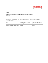
5.1 Production Test Chromatogram
Selectivity of the IonPac CS15 Analytical Column has been optimized utilizing a sulfuric acid/acetonitrile eluent at 40 °C. Using
this eluent and temperature, the weak carboxylate functionalized packing isocratically separates mono- and divalent cations in
a single injection. To guarantee that all IonPac CS15 Analytical Columns meet high quality and reproducible performance
specification standards, all columns undergo the following production control test.
As the analytical column ages it is normal to see some decrease in retention time or change in operating parameters. If the analytical
column is older than one year it is recommended to run the column under test chromatogram conditions and confirm that the column
is meeting the QAR specifications to ensure optimum performance of the column. It is recommended to repeat this performance
test once a year.
Sample Volume: 25 µL Loop (4-mm)
Column: CS15 Analytical Column (4-mm) No Guard Column
Column Temp: 40 °C
Eluent: 10 mN H2SO4/9% Acetonitrile
Eluent Flow Rate: 1.2 mL/min (4-mm)
Suppressor: Cation Self-Regenerating Suppressor, CSRS ULTRA (4-mm)
External Water Mode
or MMS Suppressor: Cation MicroMembrane Suppressor, CMMS III (4-mm)
MMS Regenerant: TBAOH
MMS Mode: Displacement Chemical Regeneration (DCR)
Expected Background Conductivity: < 3 µS
Storage Solution: Eluent
Figure 2
IonPac CS15 Production Test Chromatogram
Analyte mg/L
1. Lithium 1.0
2. Sodium 4.0
3. Ammonium 10.0
4. Magnesium 5.0
5. Calcium 10.0
6. Potassium 10.0
where 1 mg/L = 1 ppm
0 5 10 15
0
7
µS
12
345
6
Minutes

IonPac CS15 Document No. 031272-06 Page 19 of 43
5.1.1 Test Chromatogram Comparison
The following test chromatograms show the isocratic elution of ammonia, plus Group I and Group II cations (Li+, Na+, NH4
+, Mg2+,
Ca2+, and K+) on the CS15 analytical column with CG15 guard column using different isocratic eluents with the column either
at room temperature (21–25 °C) or at 40 °C.
Sample Volume: 25 µL Loop (4-mm)
Column: CS15 Analytical Column (4-mm), CG15 Guard Column (4-mm)
Column Temp: See Chromatogram
Eluent: See Chromatogram
Eluent Flow Rate: 1.2 mL/min (4-mm)
SRS Suppressor: Cation Self-Regenerating Suppressor, CSRS ULTRA (4-mm)
or MMS Suppressor: Cation MicroMembrane Suppressor, CMMS III ( 4-mm)
MMS Regenerant: TBAOH
MMS Mode: Displacement Chemical Regeneration (DCR)
Expected Background Conductivity: < 3 µS
Storage Solution: Eluent
Figure 3
IonPac CS15 Production Test Chromatogram Comparison
40 °C
Eluent: 10 mN H2SO4/9% Acetonitrile
Suppressor: External Water Mode
Room Temperature
Eluent: 13 mN H2SO4
Suppressor: Recycle Mode
40 °C
Eluent: 14 mN H2SO4
Suppressor: Recycle Mode
Room Temperature
Eluent: 10 mN H2SO4/9% Acetonitrile
Suppressor: External Water Mode
Analyte mg/L
1. Lithium 1.0
2. Sodium 4.0
3. Ammonium 10.0
4. Magnesium 5.0
5. Calcium 10.0
6. Potassium 10.0
where 1 mg/L = 1 ppm
Minutes Minutes
0 5 10 15 20 25 3
0
0
7
µS
12
34
5
6
0 5 10 15
20
25 3
0
0
7
µS
12
34
5
6
0 5 10 15 20 25 3
0
0
7
µS
1
2
3
4
5
6
0 5 10 15 20 25 3
0
0
7
µS
12
3
4
5
6
/