Page is loading ...

User Guide
MLC 60 Series
MediaLink
®
MediaLink Controllers
68-2166-01 Rev. A
12 11

This symbol is intended to alert the user of important operating and
maintenance (servicing) instructions in the literature provided with the
equipment.
This symbol is intended to alert the user of the presence of uninsulated
dangerous voltage within the product’s enclosure that may present a risk of
electric shock.
Caution
Read Instructions • Read and understand all safety and operating instructions before using the equipment.
Retain Instructions • The safety instructions should be kept for future reference.
Follow Warnings • Follow all warnings and instructions marked on the equipment or in the user information.
Avoid Attachments • Do not use tools or attachments that are not recommended by the equipment
manufacturer because they may be hazardous.
Warning
Power sources • This equipment should be operated only from the power source indicated on the product. This
equipment is intended to be used with a main power system with a grounded (neutral) conductor. The third
(grounding) pin is a safety feature, do not attempt to bypass or disable it.
Power disconnection • To remove power from the equipment safely, remove all power cords from the rear of
the equipment, or the desktop power module (if detachable), or from the power source receptacle (wall plug).
Power cord protection • Power cords should be routed so that they are not likely to be stepped on or pinched
by items placed upon or against them.
Servicing • Refer all servicing to qualified service personnel. There are no user-serviceable parts inside. To prevent
the risk of shock, do not attempt to service this equipment yourself because opening or removing covers may
expose you to dangerous voltage or other hazards.
Slots and openings • If the equipment has slots or holes in the enclosure, these are provided to prevent
overheating of sensitive components inside. These openings must never be blocked by other objects.
Lithium battery • There is a danger of explosion if battery is incorrectly replaced. Replace it only with the
same or equivalent type recommended by the manufacturer. Dispose of used batteries according to the
manufacturer’s instructions.
Ce symbole sert à avertir l’utilisateur que la documentation fournie avec le
matériel contient des instructions importantes concernant l’exploitation et la
maintenance (réparation).
Ce symbole sert à avertir l’utilisateur de la présence dans le boîtier
de l’appareil de tensions dangereuses non isolées posant des risques
d’électrocution.
Attention
Lire les instructions• Prendre connaissance de toutes les consignes de sécurité et d’exploitation avant
d’utiliser le matériel.
Conserver les instructions• Ranger les consignes de sécurité afin de pouvoir les consulter à l’avenir.
Respecter les avertissements • Observer tous les avertissements et consignes marqués sur le matériel ou
présentés dans la documentation utilisateur.
Eviter les pièces de fixation • Ne pas utiliser de pièces de fixation ni d’outils non recommandés par le
fabricant du matériel car cela risquerait de poser certains dangers.
Avertissement
Alimentations • Ne faire fonctionner ce matériel qu’avec la source d’alimentation indiquée sur l’appareil. Ce
matériel doit être utilisé avec une alimentation principale comportant un fil de terre (neutre). Le troisième
contact (de mise à la terre) constitue un dispositif de sécurité : n’essayez pas de la contourner ni de la
désactiver.
Déconnexion de l’alimentation• Pour mettre le matériel hors tension sans danger, déconnectez tous les
cordons d’alimentation de l’arrière de l’appareil ou du module d’alimentation de bureau (s’il est amovible) ou
encore de la prise secteur.
Protection du cordon d’alimentation • Acheminer les cordons d’alimentation de manière à ce que personne
ne risque de marcher dessus et à ce qu’ils ne soient pas écrasés ou pincés par des objets.
Réparation-maintenance • Faire exécuter toutes les interventions de réparation-maintenance par un
technicien qualifié. Aucun des éléments internes ne peut être réparé par l’utilisateur. Afin d’éviter tout danger
d’électrocution, l’utilisateur ne doit pas essayer de procéder lui-même à ces opérations car l’ouverture ou le
retrait des couvercles risquent de l’exposer à de hautes tensions et autres dangers.
Fentes et orifices • Si le boîtier de l’appareil comporte des fentes ou des orifices, ceux-ci servent à empêcher les
composants internes sensibles de surchauffer. Ces ouvertures ne doivent jamais être bloquées par des objets.
Lithium Batterie • Il a danger d’explosion s’ll y a remplacment incorrect de la batterie. Remplacer uniquement
avec une batterie du meme type ou d’un ype equivalent recommande par le constructeur. Mettre au reut les
batteries usagees conformement aux instructions du fabricant.
Safety Instructions • English
Consignes de Sécurité • Français
Sicherheitsanleitungen • Deutsch
Dieses Symbol soll dem Benutzer in der im Lieferumfang enthaltenen
Dokumentation besonders wichtige Hinweise zur Bedienung und Wartung
(Instandhaltung) geben.
Dieses Symbol soll den Benutzer darauf aufmerksam machen, daß im Inneren
des Gehäuses dieses Produktes gefährliche Spannungen, die nicht isoliert sind
und die einen elektrischen Schock verursachen können, herrschen.
Achtung
Lesen der Anleitungen • Bevor Sie das Gerät zum ersten Mal verwenden, sollten Sie alle Sicherheits-und
Bedienungsanleitungen genau durchlesen und verstehen.
Aufbewahren der Anleitungen • Die Hinweise zur elektrischen Sicherheit des Produktes sollten Sie
aufbewahren, damit Sie im Bedarfsfall darauf zurückgreifen können.
Befolgen der Warnhinweise • Befolgen Sie alle Warnhinweise und Anleitungen auf dem Gerät oder in der
Benutzerdokumentation.
Keine Zusatzgeräte • Verwenden Sie keine Werkzeuge oder Zusatzgeräte, die nicht ausdrücklich vom
Hersteller empfohlen wurden, da diese eine Gefahrenquelle darstellen können.
Vorsicht
Stromquellen • Dieses Gerät sollte nur über die auf dem Produkt angegebene Stromquelle betrieben werden.
Dieses Gerät wurde für eine Verwendung mit einer Hauptstromleitung mit einem geerdeten (neutralen) Leiter
konzipiert. Der dritte Kontakt ist für einen Erdanschluß, und stellt eine Sicherheitsfunktion dar. Diese sollte nicht
umgangen oder außer Betrieb gesetzt werden.
Stromunterbrechung • Um das Gerät auf sichere Weise vom Netz zu trennen, sollten Sie alle Netzkabel aus der
Rückseite des Gerätes, aus der externen Stomversorgung (falls dies möglich ist) oder aus der Wandsteckdose
ziehen.
Schutz des Netzkabels • Netzkabel sollten stets so verlegt werden, daß sie nicht im Weg liegen und niemand
darauf treten kann oder Objekte darauf- oder unmittelbar dagegengestellt werden können.
Wartung • Alle Wartungsmaßnahmen sollten nur von qualiziertem Servicepersonal durchgeführt werden.
Die internen Komponenten des Gerätes sind wartungsfrei. Zur Vermeidung eines elektrischen Schocks
versuchen Sie in keinem Fall, dieses Gerät selbst öffnen, da beim Entfernen der Abdeckungen die Gefahr eines
elektrischen Schlags und/oder andere Gefahren bestehen.
Schlitze und Öffnungen • Wenn das Gerät Schlitze oder Löcher im Gehäuse aufweist, dienen diese zur
Vermeidung einer Überhitzung der empndlichen Teile im Inneren. Diese Öffnungen dürfen niemals von
anderen Objekten blockiert werden.
Litium-Batterie • Explosionsgefahr, falls die Batterie nicht richtig ersetzt wird. Ersetzen Sie verbrauchte Batterien
nur durch den gleichen oder einen vergleichbaren Batterietyp, der auch vom Hersteller empfohlen wird.
Entsorgen Sie verbrauchte Batterien bitte gemäß den Herstelleranweisungen.
Este símbolo se utiliza para advertir al usuario sobre instrucciones
importantes de operación y mantenimiento (o cambio de partes) que se
desean destacar en el contenido de la documentación suministrada con los
equipos.
Este símbolo se utiliza para advertir al usuario sobre la presencia de
elementos con voltaje peligroso sin protección aislante, que puedan
encontrarse dentro de la caja o alojamiento del producto, y que puedan
representar riesgo de electrocución.
Precaucion
Leer las instrucciones • Leer y analizar todas las instrucciones de operación y seguridad, antes de usar el
equipo.
Conservar las instrucciones • Conservar las instrucciones de seguridad para futura consulta.
Obedecer las advertencias • Todas las advertencias e instrucciones marcadas en el equipo o en la
documentación del usuario, deben ser obedecidas.
Evitar el uso de accesorios • No usar herramientas o accesorios que no sean especificamente
recomendados por el fabricante, ya que podrian implicar riesgos.
Advertencia
Alimentación eléctrica • Este equipo debe conectarse únicamente a la fuente/tipo de alimentación eléctrica
indicada en el mismo. La alimentación eléctrica de este equipo debe provenir de un sistema de distribución
general con conductor neutro a tierra. La tercera pata (puesta a tierra) es una medida de seguridad, no
puentearia ni eliminaria.
Desconexión de alimentación eléctrica • Para desconectar con seguridad la acometida de alimentación
eléctrica al equipo, desenchufar todos los cables de alimentación en el panel trasero del equipo, o desenchufar
el módulo de alimentación (si fuera independiente), o desenchufar el cable del receptáculo de la pared.
Protección del cables de alimentación • Los cables de alimentación eléctrica se deben instalar en lugares
donde no sean pisados ni apretados por objetos que se puedan apoyar sobre ellos.
Reparaciones/mantenimiento • Solicitar siempre los servicios técnicos de personal calicado. En el interior no
hay partes a las que el usuario deba acceder. Para evitar riesgo de electrocución, no intentar personalmente la
reparación/mantenimiento de este equipo, ya que al abrir o extraer las tapas puede quedar expuesto a voltajes
peligrosos u otros riesgos.
Ranuras y aberturas • Si el equipo posee ranuras o orificios en su caja/alojamiento, es para evitar el
sobrecalientamiento de componentes internos sensibles. Estas aberturas nunca se deben obstruir con otros
objetos.
Batería de litio • Existe riesgo de explosión si esta batería se coloca en la posición incorrecta. Cambiar esta
batería únicamente con el mismo tipo (o su equivalente) recomendado por el fabricante. Desachar las baterías
usadas siguiendo las instrucciones del fabricante.
Instrucciones de seguridad • Español
安全须知 • 中文
这个符号提示用户该设备用户手册中有重要的操作和维护说明。
这个符号警告用户该设备机壳内有暴露的危险电压,有触电危险。
注意
阅读说明书 • 用户使用该设备前必须阅读并理解所有安全和使用说明。
保存说明书 • 用 户应保存安全说明书以备将来使用。
遵守警告 • 用户应遵守产品和用户指南上的所有安全和操作说明。
避免追加 • 不要使用该产品厂商没有推荐的工具或追加设备,以避免危险。
警告
电源 • 该设备只能使用产品上标明的电源。 设备必须使用有地线的供电系统供电。 第三条线(
地线)是安全设施,不能不用或跳过 。
拔掉电源 • 为安全地从设备拔掉电源,请拔掉所有设备后或桌面电源的电源线,或任何接到市电
系统的电源线。
电源线保护 • 妥善布线, 避免被踩踏,或重物挤压。
维护 • 所有维修必须由认证的维修人员进行。 设备内部没有用户可以更换的零件。为避免出现触
电危险不要自己试图打开设备盖子维修该设备。
通风孔 • 有些设备机壳上有通风槽或孔,它们是用来防止机内敏感元件过热。 不要用任何东西
挡住通风孔。
锂电池 • 不正确的更换电池会有爆炸的危险。必须使用与厂家推荐的相同或相近型号的电池。按
照生产厂的建议处理废弃电池。
Precautions/Safety Instructions ii
FCC, Copyright, and Trademark Information iii

FCC Class A Notice
This equipment has been tested and found to comply with the limits for a Class A digital device, pursuant to part 15
of the FCC Rules. Operation is subject to the following two conditions:
1. This device may not cause harmful interference.
2. This device must accept any interference received, including interference that may cause undesired operation.
The Class A limits are designed to provide reasonable protection against harmful interference when the equipment
is operated in a commercial environment. This equipment generates, uses, and can radiate radio frequency energy
and, if not installed and used in accordance with the instruction manual, may cause harmful interference to radio
communications. Operation of this equipment in a residential area is likely to cause harmful interference, in which
case the user will be required to correct the interference at his own expense.
NOTE: This unit was tested with shielded cables on the peripheral devices. Shielded cables must be used with
the unit to ensure compliance with FCC emissions limits.
For more information on safety guidelines, regulatory compliances, EMI/EMF compliance, accessibility, and
related topics, click here.
iii

Conventions Used in this Guide
Notifications
In this user guide, the following are used:
CAUTION: A caution indicates a potential hazard to equipment or data.
NOTE: A note draws attention to important information.
TIP: A tip provides a suggestion to make working with the application easier.
WARNING: A warning warns of things or actions that might cause injury, death, or
other severe consequences.
Software Commands
Commands are written in the fonts shown here:
^AR Merge Scene,,Op1 scene 1,1 ^B 51 ^W^C
[01] R 0004 00300 00400 00800 00600 [02] 35 [17] [03]
E
X!
*
X1&
*
X2)
*
X2#
*
X2!
CE
}
NOTE: For commands and examples of computer or device responses mentioned
in this guide, the character “0” is used for the number zero and “O”
represents the capital letter “o.”
Computer responses and directory paths that do not have variables are written in the font
shown here:
Reply from 208.132.180.48: bytes=32 times=2ms TTL=32
C:\Program Files\Extron
Variables are written in slanted form as shown here:
ping xxx.xxx.xxx.xxx —t
SOH R Data STX Command ETB ETX
Selectable items, such as menu names, menu options, buttons, tabs, and field names are
written in the font shown here:
From the File menu, select New.
Click the OK button.
Copyright
© 2011 Extron Electronics. All rights reserved.
Trademarks
All trademarks mentioned in this guide are the properties of their respective owners.
iv

Contents
Introduction ......................................................... 1
About This Guide ................................................ 1
About the MLC 60 Series MediaLink Controllers . 1
MLC Models ................................................... 1
Features .......................................................... 3
MLC Configuration Software .......................... 5
Device Drivers ................................................. 5
Application Diagrams ...................................... 5
System Requirements .......................................... 7
Features, Installation, and Operation ....... 8
Installation Overview ........................................... 8
Front and Left Side Panels ................................... 9
MLC D Front Panels......................................... 9
MLC 62 RS EU and MLC 62 RS MK Front a
nd Side Panels .............................................. 11
Buttons ......................................................... 13
Rear Panel Features ........................................... 14
Rear Panel Features on MLC 62 RS EU and
MLC 62 RS MK Only .................................... 16
MLC 64 RS VC D Volume Control Module
Rear Panel .................................................... 16
Installation ........................................................ 17
Removing and Replacing the Faceplates ........ 17
Replacing Buttons ......................................... 21
Wiring for RS-232 Control
(RS Models Only) .......................................... 22
Wiring for IR Control ..................................... 23
Wiring the Relays Port (RS Models Only) ........ 23
Wiring the Digital Input Port
(RS Models Only) .......................................... 24
Wiring the Host/Cong Port .......................... 25
Wiring the Volume Control Module
(MLC 64 RS VC D Only) ................................ 26
Connecting Power to the MLC ...................... 26
Conguring the MLC via the USB Port .............. 27
IR Learning .................................................... 30
Mounting the MLC 60 Series Controllers ........... 31
Mounting an MLC 62 D ............................... 31
Mounting the MLC 64 RS VC D .................... 33
Mounting the MLC 62 RS EU and the
MLC 62 RS MK ............................................ 35
Mounting the MLC EU in a Raceway Using
Spacers (Optional) ........................................ 36
Accessing Covered Panel Features After
Mounting ........................................................ 38
Accessing the Covered MLC D Front Panel
Features ....................................................... 38
Accessing MLC 62 RS EU and
MLC 62 RS MK Side and Rear Panel
Features ....................................................... 38
Front Panel Security Lockout ............................. 39
Locking Using the Front Panel Buttons ......... 39
Resetting the MLC Using the Reset Button ....... 40
Software-based Configuration .................. 41
About the MLC Configuration Program ............ 41
Computer System Requirements ................... 41
Installing the Configuration Software ................ 42
Downloading and Installing the Software
from the Web .............................................. 42
Installing the Software from the DVD ........... 42
Starting the Configuration Software ................. 43
Accessing the Help File .................................. 45
Obtaining Device Drivers ................................... 46
Downloading Drivers Using the
Configuration Program ............................... 46
Downloading Drivers from the Disc ............... 49
Downloading Drivers from the Web .............. 52
SIS Control .......................................................... 54
Host-to-Controller Communications .................. 54
Controller-initiated Messages ........................ 54
Error Responses............................................. 54
Using the Command and Response Table .......... 55
Symbol Definitions ........................................ 55
Command and Response Table for SIS
Commands ...................................................... 58
Reference Information .................................. 62
Specifications .................................................... 62
MLC 62 Series Specifications ......................... 62
MLC 64 RS VC D Specications ..................... 66
Part Numbers and Accessories ........................... 69
Included Parts ............................................... 69
Accessories ................................................... 72
MLC 60 Series MediaLink Controllers • Contents v

MLC 60 Series MediaLink Controllers • Contents vi

Introduction
This section gives an overview of the guide and describes the MLC 60 Series MediaLink
®
Controllers and their features. Topics include:
• About This Guide
• About the MLC 60 Series MediaLink Controllers
• System Requirements
About This Guide
This guide provides detailed information and best practice recommendations about cabling
and configuring the Extron MLC 60 Series MediaLink Controllers. It provides reference
information about specifications, dimensions, and programming of the controllers.
Throughout this guide the general terms “MLC” and “controller” are used interchangeably
to refer to any MLC 60 Series controller. “MLC D models” applies to the MLC 62 RS D,
MLC 62 IR D, and the MLC 64 RS VC D. “MLC 62” applies to all MLC 60 Series models
except the MLC 64.
About the MLC 60 Series MediaLink Controllers
The Extron MLC 60 Series MediaLink Controllers are panels that control a wide range of
audio/video systems in any classroom, meeting facility, or auditorium via RS-232 or IR. They
act as extended remote control panels, featuring eight (optionally six) labeled backlit buttons
for the MLC 62 models or six for the MLC 64 RS VC D. These buttons can be configured via
the MLC Windows
®
-based configuration software to control power, input switching, and
volume on a display device or switcher. If desired, you can replace these buttons with ones
having different labels, which also are provided with the controller.
The MLC 64 RS VC D model has, in addition to the configurable buttons, a volume control
module containing an analog volume control knob and a Mute button. An Extron amplifier
can be connected to this module for volume control via the MLC.
All models can control a projector, display, or switcher via IR. In addition, the MLC 62 RS
models can control display devices, switchers, and various other items such as lights, a
projector lift, or a motorized screen via RS-232, IR, relays, or digital input.
The MLC controllers are housed in secure, compact, one-gang and two-gang sized
enclosures, which can be mounted on a wall or furniture, with or without an electrical
junction box or mounting bracket.
MLC Models
MLC 62 IR D — US model. Controls devices by IR only; has a one-gang Decora® faceplate
and fits in a one-gang US electrical box.
MLC 62 RS D — US model. Controls devices by RS-232, IR, relays, and digital input; has a
one-gang Decora faceplate and fits in a one-gang US electrical box.
MLC 62 RS EU — European model. Controls devices by RS-232, IR, relays, and digital input;
has a one-gang Jung frame and fits over a standard one-gang EU electrical box.
MLC 60 Series MediaLink Controllers • Introduction 1

MLC 62 RS MK — UK model. Controls devices by RS-232, IR, relays, and digital input; has
a standard MK sized frame and fits into a standard one-gang MK electrical box.
MLC 64 RS VC D — US model. Controls devices by RS-232, IR, relays, and digital input;
has a two-gang Decora faceplate and fits in a two-gang US electrical box. Contains a
volume control module with an analog potentiometer for volume control of an Extron
amplifier.
NOTE: Only an Extron amplifier with remote volume control capability can be used
with this model.
VOLUME
Extron
DISPLAY
ON
OFF
VIDEO
PC
VOLUME
Extron
DISPLAY
ON
OFF
PC
VIDEO
LAPTOP
MUTE
MLC 62 IR D MLC 62 RS D
Extron
VOLUME
DISPLAY
ON
OFF
LAPTOP MUTE
PC VIDEO
Extron
VOLUME
DISPLAY
ON
OFF
VIDEO
PC
MUTE
LAPTOP
MLC 62 RS EU MLC 62 RS MK
AUX
LAPTOP
PC
MUTE
Extron
DISPLAY
VOLUME
ON
OFF
VIDEO
MUTE
V
O
LUM
E
MLC 64 RS VC D
Figure 1. MLC 60 Series Models
MLC 60 Series MediaLink Controllers • Introduction 2

The five MLC models have the same button functionality and use the same configuration
software. All models can be controlled by pressing the front panel buttons or via a host
device using RS-232 communication and simple ASCII commands (Simple Instruction Set,
SIS
™
). They differ from each other in the following ways:
• The MLC 62 IR D rear panel does not contain the Relay, Digital Input, or RS-232
control ports that the RS models have.
• The MLC 64 front panel has seven buttons, one of which (the Mute button) is located
below the Volume knob. This button is used only to mute and unmute the volume on
an Extron amplier and cannot be congured to perform other functions.
• Some front, side, and rear panel connectors are located in different places on the
MLC RS D (US), EU (Europe), and MK (United Kingdom) models (see “Panels and
Connectors” in the “Features, Cabling, and Operation” section).
Faceplate alternatives
The MLC 60 Series models are available with the following faceplate configurations:
• MLC 62 IR D: The US IR model is delivered with two six-button faceplates in black and
white. One black and one white Decora wallplate are also provided. An eight-button
faceplate is available to order.
• MLC 62 RS D: The US RS-232 model is delivered with two eight-button faceplates
in black and white. One black and one white Decora wallplate are also provided. A
six-button faceplate is available to order.
• MLC 62 RS EU: The European model is delivered with six-button and eight-button
faceplates, both in RAL9010 white.
• MLC 62 RS MK: The UK model is delivered with six-button and eight-button
faceplates, both in white.
• MLC 64 RS VC D: The MLC 64 is delivered with seven-button faceplates in black and
white.
Features
Some of the features of MLC 60 Series include:
• Customizable buttons — Eight buttons are standard on the MLC 62 RS models,
prelabeled as shown in figure 1 on the previous page. The MLC 62 IR D has six
prelabeled buttons, and the MLC 64 RS VC D has seven.
An additional set of prelabeled buttons is included with each model, enabling the
controller to be customized to suit the application.
Additional buttons are available to order for all models, labeled in English (the default)
and other languages. Buttons can be ordered with custom labeling as well.
• Button backlighting — The front panel buttons are backlit to facilitate use in
low-light environments and to provide certain status (such as whether power is on or
off, or which input has been selected).
• Alternative six-button configuration (MLC 62 RS models only) — For
applications in which input device or button functions are not necessary, the standard
eight-button faceplate on the MLC 62 RS can be replaced with a six-button one. Each
pair of source selection buttons can be changed to a long, single function button.
• Device drivers — A wide variety of Extron certied, ready-to-use device drivers are
available via the MLC configuration software, the provided MLC software disk, and
the Extron website (www.extron.com).
MLC 60 Series MediaLink Controllers • Introduction 3

• IR and RS-232 ports — The MLC 64 and the MLC 62 RS models each have a
dedicated serial port for communicating with most types of projectors or flat
panel displays via unidirectional RS-232. They also have an IR/S port, which can be
configured for IR or RS-232 control.
The MLC 62 IR D has only an IR port, which is used for IR communication only.
IR and RS-232 display drivers can be downloaded and used to configure the controller.
• Relays (RS models) — Two relay ports enable control of room devices such as lights,
motorized screens, and projector lifts.
• Digital Input (RS models) — A Digital Input port enables monitoring of a switch or
sensor to control devices.
• IR Learning — The MLC can be configured by IR learning, using the remote control
of a switcher or display device to create an IR driver that enables the MLC to control
the device.
• USB configuration port — The MLC can be congured via a USB mini B port,
located on the front or side panel (depending on the model). This port can also
temporarily provide power to the MLC during configuration.
• Volume adjustment:
• The MLC 62 models have individual Volume Up and Down buttons for audio level
control, with ve LEDs that indicate current audio settings.
• The MLC 64 has a volume control module with an analog potentiometer knob to
control the audio level for an Extron amplier that is enabled for remote volume
control. The volume control module also contains a Mute button for muting and
unmuting the audio (this button cannot be reprogrammed).
NOTE: Only Extron amplifiers can be controlled via the MLC 64 volume
control module.
• Macro capability — Each button can be congured to execute multiple actions
through the serial or IR control ports. For example, a button can be configured so that
a single press triggers commands to turn on a display, select the RGB input of the
display, and trigger a relay.
• Toggling — Buttons can be placed in toggle mode, which adds exibility by enabling
two different sets of commands to be executed with alternating presses of the button.
• Built-in speaker — A speaker provides audible feedback to confirm user actions
when buttons are pressed (except for the Mute button on the VCM module of the
MLC 64 RS VC D).
• Inactivity timer for display shutoff — An adjustable timer controls automatic
shutdown after a specified period of inactivity.
• Front panel security lockout — If the MLC is installed in an unsecured environment
where easy access is not desirable, a security lockout feature can be implemented to
lock out all front panel controls.
• Activity LED — A small LED at the top of the MLC front panel lights red, green, or
amber to indicate button presses, data transfer, front panel lockout, and other actions.
• Section 508 Compliant — The MLC meets or exceeds accessibility standards
for Electronic Information Technology. For more information about the
Extron Commitment to Accessibility, see the Extron Accessibility web page at
www.extron.com/company/article.aspx?id=accessibility.
MLC 60 Series MediaLink Controllers • Introduction 4

MLC Configuration Software
The included MLC Configuration Program is used to configure the MLC buttons and
ports via an RS-232 or USB connection. This software, provided on a DVD that is
delivered with the product, enables you to set functions for the front panel buttons
and to configure the MLC ports in order to control devices via the MLC. The software
works in combination with the IR or RS-232 drivers, also provided with the MLC on
DVD or at www.extron.com (see “Installing the Configuration Software” in the
“Software-based Configuration” section to access this program).
Device Drivers
The MLC can control a switcher, projector, or other display device via IR or RS-232
communication. The MLC must have drivers loaded for the devices it will control in order
to send commands to those devices. Drivers can be obtained in the following ways:
• You can install IR or an RS-232 driver files from a disk, download them from the
Extron website (www.extron.com), or download them from Extron via the driver
subscription feature within the Windows-based conguration program. The drivers
are saved on your computer in a folder located at c:\Documents and Settings\
All Users\Shared Documents\Extron\Driver2 (Windows XP) or c:\Users\
Public\Documents\Extron\Driver2 (Windows 7). You can upload the desired
drivers to the MLC using the MLC configuration software.
• You can capture IR commands from the IR remote control of a device through
IR Learning using the MLC configuration program to create a driver that the MLC
can use. When a driver is created, it can be added to the conguration program so
that the commands can be used to configure the MLC to control the device (see the
MLC 60 Series help to configure the MLC using IR Learning).
Application Diagrams
100-240V
1.0A MAX.
50-60Hz
AUDIO INPUTS
LINE LEVEL
MONO
AUDIO
AUDIO
AUX/MIX
ADJUST
-42dB
TO
+24dB
L
R
L
R
R
1
2
INPUTS
OUTPUTS
VIDEO
H
V
B
G
R
1
2
INPUTS
5
6
LINEOUT
RS-232/MLC/IR
Tx
Rx
IR
12V
A
B
C
PREAMP
MONITOR OUT
L
R
L
R
CLASS 2 WIRING
AMPLIFIED OUTPUT
4/8
ohm
RIG HT
LEF T
STEREO OR DU AL MONO
PC
DVD/VCR
Amplied Output
RS-232 or
IR Projector
Control
Video
Video
Extron
MLS 304SA
MediaLink
®
Switcher
Laptop
w/ Audio
Projector
Audio
Audio
VGA
Extron
SI 3
Surface-Mount
Speakers
RS-232
Switcher
Control
Screen
Control
VGA
VGA
VGA
Relay
Extron
MLC 62 RS D
MediaLink Controller
VOLUME
DISPLAY
ON
OFF
PC
VIDEO
LAPTOP
MUTE
Figure 2. MLC 62 RS D Controlling an MLS 304 SA Switcher and a Projector
MLC 60 Series MediaLink Controllers • Introduction 5

VOLUME
DISPLAY
PC
VIDEO
ON
OFF
PC
DVD
Projector with
Internal Speakers
IR Projector Control
Video
VGA
Audio
Audio
• IR Display Control
• On/Off Control
• Input Switching
• Volume Control
Extron
MLC 62 IR D
MediaLink Controller
Figure 3. MLC 62 IR D Controlling a Projector
Projector
with Switched
Audio Output
Screen
Control
PC
Relay
Extron
SI 3
Surface-Mount
Speakers
RS-232
Display Control
DVD
Video
Laptop
Audio
VGA
Audio
Audio
VGA
Extron
MPA 122
Mini Power
Amplifier
BASSLEVEL
TREBLE
MINI POWER AMPLIFIER
MPA 122
ON
OFF
LIMITER
STEREO
DUAL
MONO
Extron
MLC 62 RS EU
MediaLink
®
Controller
DISPLAY
VOLUME
LAPTOP MUTE
PC VIDEO
ON OFF
Figure 4. MLC 62 RS EU Controlling a Projector and Screen
MLC 60 Series MediaLink Controllers • Introduction 6

S-video
Audio
POWER
12V
3A MAX
OUTPUT
4/8
OHMS
INPUTS
L
R
L
R
REMOTE
VOL/MUTE
10V
50mA
L
MPA 152
R
C
US
LISTED
17TT
AUDIO/VIDEO
APPARATUS
CLASS 2 WIRING
DO NOT GROUND
OR SHORT
SPEAKER OUTPUTS!
Projector
with Switched
Audio Output
Screen
Control
PC
Relay
Extron
MLC 64 RS VC D
MediaLink Controller
Extron
SI 3
Surface-Mount
Speakers
RS-232
Display Control
Volume Control
DVD
Video
Laptop
Audio
VGA
Audio
VGA
Extron
MPA 152
Mini Power
Amplier
Document
Camera
MUTE
VOLUME
DISPLAY
OFF
ON
AUX
LAPTOP
PC
VIDEO
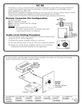
Figure 5. MLC 64 RS VC D Controlling a Projector and Screen
System Requirements
The minimum PC system requirements for installing the configuration software include:
• Intel
®
Pentium
®
III 1-GHz processor
• Microsoft
®
Windows XP SP2 and Windows 7
• Microsoft.NET Framework 2.0
• 512 MB of RAM
• 50 MB of available hard disk space
MLC 60 Series MediaLink Controllers • Introduction 7

Features,
Installation, and
Operation
This section describes the front, side, and rear panel features of the five MLC models, and
provides procedures for installing and operating them. Topics include:
• Installation Checklist
• Panels and Connectors
• Installation
• Configuring the MLC via the USB Port
• Mounting the MLC 60 Series Controllers
• Accessing Covered Panel Features After Mounting
• Front Panel Security Lockout (Executive Mode)
• Resetting the MLC Using the Reset Button
• IR Learning
Installation Overview
1. Prepare the installation site as follows:
a. Measure and cut the hole in the mounting surface.
b. Prepare and pull the cables through the electrical box or mounting bracket.
c. Install the electrical box or mounting bracket. (Installation instructions for the
electrical box are provided with it.)
2. (Optional) Make any desired changes to the buttons installed in the faceplate,
substituting any of the provided additional buttons (see Replacing Buttons, later in
this section).
NOTE: The Mute button on the MLC 64 volume control module cannot be
configured.
3. Attach the cables to the rear panel connectors of the MLC and to the display device
or switcher. Attach optional IR Emitters if used, and any switches or sensors needed
for other room devices, such as lights, a motorized screen, and so forth). See the
following sections as needed for cabling information:
• Rear Panel Features
• Wiring for RS-232 Control
• Wiring for IR Control
• Wiring the Relays Port
• Wiring the Digital Input Port
MLC 60 Series MediaLink Controllers • Features, Installation, and Operation 8

4. Wire and connect the MLC power supply (see “Connecting Power to the MLC,”
later in this section). Connect all other power cords and turn on all the devices,
including the MLC.
5. Connect a configuration cable from the computer to the MLC by doing either of the
following:
• Connect a USB A to mini B cable to the MLC USB conguration port and to a USB
port on your computer (see “Configuring the MLC via the USB Port,” later in
this section).
• Connect an RS-232 cable to the provided 3-pole connector and connect it
between the MLC Host/Cong port and the computer serial port (see “Wiring
the Host/Config Port,” later in this section).
6. Download and install the MLC Configuration Program (see “Installing the
Configuration Software,” in the “Software-based Configuration” section).
7. Download or create drivers for the devices you will be connecting (see “Obtaining
Device Drivers” or “Configuring Using IR Learning” in the “Software-based
Configuration” section).
8. Configure the MLC buttons and ports using the configuration program. (See the
configuration program help file for these procedures. To access the help file, see
“Installing the Configuration Software” in the “Software Configuration and
Control” section.)
If you are configuring via the USB port, remove the USB cable when you are finished.
9. Test the system: press the MLC buttons, watch the display, and listen to the audio
output to determine whether the connected devices are responding correctly
(powering on and off, switching inputs, and so forth). If not, ensure all devices are
plugged in and receiving power. Check the cabling and make needed adjustments.
10. Disconnect power from the MLC at the source and from all other devices in the
system.
11. Mount the MLC to the mounting surface, following the appropriate procedure for
your MLC model, discussed later in this section:
• For MLC 62 D models, see “Mounting the MLC 62 D.”
• For MLC 62 RS EU and MK models, see “Mounting the MLC 62 RS EU and the
MLC 62 RS MK.”
• For the MLC 64, see “Mounting the MLC 64 RS VC D.”
12. Restore power to the MLC and to the connected devices.
Front and Left Side Panels
MLC D Front Panels
The front panels of the MLC 62 RS D, the MLC 62 IR D, and MLC 64 models contain
buttons and indicators that are visible and accessible after the MLC has been mounted.
Other front panel controls and connectors are located behind the MLC wallplate and are
not visible after mounting (see “Controls behind the wallplate,” later in this section).
MLC 60 Series MediaLink Controllers • Features, Installation, and Operation 9

The numbered callouts below apply to all the following MLC D front panel drawings.
a Activity LED
b Display power On
and Off Buttons
c Volume buttons and
LEDs (MLC 62 models only)
d Input Selection buttons
e Reset LED
f Reset button
g USB configuration port
h DIP switches
i IR Learning sensor
j On button identification nub
k Mute button (MLC 64 only)
l Volume control knob
MLC 64 RS VC D only)
MLC 62 D front panels
By default, the MLC 62 RS D has eight front panel buttons, and the MLC 62 IR D has six.
Both models also have indicator LEDs for volume and activity.
VOLUME
DISPLAY
ON
OFF
PC
VIDEO
LAPTOP
MUTE
1
2
Extron
4
10
3
VOLUME
Extron
DISPLAY
ON
OFF
VIDEO
PC
MLC 62 RS D
MLC 62 IR D
4
Figure 6. MLC 62 RS D and MLC 62 IR D Front Panels
MLC 64 RS VC D front panel
The MLC 64 RS VC D front panel contains seven buttons, an Activity LED, and a volume
control knob.
VIDEO
AUX
LAPTOP
PC
Extron
DISPLAY
ON
OFF
MUTE
VOLUME
MUTE
VOLUM
E
11
12
1
2
4
Figure 7. MLC 64 RS VC D Front Panel
MLC 60 Series MediaLink Controllers • Features, Installation, and Operation 10

Controls behind the wallplate
The front panels of the MLC D controllers contain some controls and connectors that are
located behind the wallplate when the controller is mounted. To access these features that
are covered during normal operation, you must remove the wallplate (see “Accessing the
Covered MLC D Front Panel Features,” later in this section).
VOLUME
DISPLAY
5
6
7
9
Extron
PC
VIDEO
LAPTOP
MUTE
ON
OFF
8
MUTE
VOLUME
MUT
E
VO
L
U
ME
AUX
LAPTOP
PC
Extron
DISPLAY
ON
OFF
VIDEO
MLC 62 RS D
MLC 64 RS VC D
Figure 8. MLC D Front Panel Controls Behind the Wallplate
MLC 62 RS EU and MLC 62 RS MK Front and Side Panels
The MLC 62 RS EU and MLC 62 RS MK front panels contain the same buttons and
indicators as the MLC 62 D models. Other connectors and controls are on the left side
panel; to access these features, you must remove the MLC from the installation surface.
When the MLC is removed, the wall frame is released from the mounting surface as
well, leaving the metal mounting bracket in place (see “Accessing the MLC 62 RS EU
and MLC 62 RS MK Side and Rear Panel Features,” later in this section, for removal
procedures).
VOLUME
DISPLAY
Front View
7
Left Side View
9
LAPTOP MUTE
PC VIDEO
ON OFF
1
4
Extron
2
3
10
Figure 9. MLC 62 RS EU and MLC 62 RS MK Front and Side Panels
NOTE: The MLC 62 RS MK is the same size and has the same front and side panel
features as the MLC 62 RS EU, with the exception of its larger wall frame,
which fits over an MK electrical box.
MLC 60 Series MediaLink Controllers • Features, Installation, and Operation 11

Front panel features
a
Activity LED — This bicolored LED lights green when the MLC front panel buttons
are pressed. It blinks red while enabling front panel lockout (executive mode).
b
Display power On and Off buttons — After configuring these buttons, use them
to turn the connected display device or switcher on and off.
The face of the On button contains a nub (
j
), which helps you to identify the button
by touch. When the On button is pressed, it blinks rapidly while the connected device
is warming up. When the Off button is pressed, it blinks slowly while the device
is cooling down. When this delay period has elapsed, the power button that was
pressed remains brightly lit.
By default, only one of these two buttons can be selected (active) at once. Using the
MLC configuration software, you can associate other functions and relays with each
of these buttons (see the configuration software help file).
c
Volume buttons and LEDs (MLC 62 models only) — Use these buttons to adjust
the audio volume. Each Volume button flashes when pressed and continues to flash
while being held.
The volume indicator LEDs above the buttons give indications of change to the volume
level as follows:
• When the RS-232 or IR/S port has been congured with a serial driver that
contains a volume table, the ve LEDs light in order from left to right to show
volume level increments.
• If the current driver does not contain a volume table, the rst two LEDs on the left
blink each time the Volume Down button is pressed, and the last two LEDs on the
right blink each time the Volume Up button is pressed, indicating a volume level
decrement or increment.
d
Input selection buttons — These buttons can be used to select the desired audio or
video input for the connected device or for a variety of other functions. By default the
buttons are set up as follows:
• MLC 62 RS models: Three of these buttons are set to input mode, meaning that
they are a mutually exclusive group and only one of the buttons can be selected
(active) at a time. The active input button remains brightly lit, while all other input
buttons remain dimly lit. The fourth button, labeled Mute, is set in Toggle mode
and is not grouped with the others.
• MLC 62 IR D: Two double-sized buttons are grouped in input mode and are
mutually exclusive.
• MLC 64 RS: Four double-sized buttons are grouped in input mode and are
mutually exclusive.
You can change this button behavior by using the configuration software to change
the operating mode of the button (see the MLC 60 Series configuration program help
file for more information).
e
Reset LED — Indicates the status of a reset in progress.
f
Reset button — Press this reset button to initiate factory firmware or configuration
resets (see “Resetting the MLC Using the Reset Button,” later in this section).
MLC 60 Series MediaLink Controllers • Features, Installation, and Operation 12

g
USB configuration port — Connect a USB cable (USB A to mini B) between
your computer and this port to configure the MLC via the configuration software
and to update the firmware. This port can also provide power to the MLC during
configuration.
NOTE: Do not use this port as the permanent power source for the MLC. It
should be used for power only during button and port configuration.
• On the MLC D models, the USB port is located at the right edge of the front
panel behind the wallplate. To access this port after installation, you must remove
the wallplate from the unit.
• On the MLC 62 EU and MK, the USB port is located on the left side panel. To
access this port after installation, you must detach the MLC from the installation
surface.
h
DIP switches — Reserved for future use
i
IR Learning sensor — This sensor enables the MLC to learn IR commands from the
hand-held remote control of a display device or switcher. The IR-learned commands
are used to create an IR driver, then configured to be played back with any button
press (see “IR Learning,” later in this section).
NOTE: Before performing IR Learning to create a driver, check to see if an Extron
driver exists for your device (see “Obtaining Device Drivers” in the
“Software-based Configuration” section).
j On button Identication nub — Power On button face contains a raised nub that
helps you to identify the On button by touch in a dark or dimly lit room.
k Mute button (MLC 64 only) — Press this toggle button to mute and unmute the
volume on the Extron amplifier connected to the volume control module.
l Volume control knob (MLC 64 only) — Rotate this knob to increase or decrease the
volume on the Extron amplifier connected to the volume control module.
Buttons
The front panel button illumination provides status on what the MLC is doing. The buttons
are lit while the MLC has power. When a button has been pressed and is active or on, it
lights brightly. While a button is inactive or off, it is lit dimly.
When buttons are grouped together, only the button that is pressed lights brightly. The
other buttons in the group remain dim. (See the configuration software help file for
information on grouping buttons; see “Installing the Configuration Software” in the
“Software Configuration and Control” section to obtain the software.)
You can remove buttons and replace them with buttons having different labels. You can
then configure the new buttons with the functions that their labels represent, using the
configuration software (see the MLC 60 Series configuration program help file for detailed
procedures for configuring the buttons).
Each Display On/Off and input selection button can be set up to perform a sequence of
several functions, which can be combinations of the following options:
• A driver operation — Execute an RS-232 or IR control command that is part of a
device driver (for a projector, VCR, DVD player, switcher, and so forth).
• A relay operation — Execute a relay command to a room device such as a motorized
screen or a projector lift.
• Setting a time delay — Insert delays between executed commands.
MLC 60 Series MediaLink Controllers • Features, Installation, and Operation 13

• Setting the button flashing rate — Specify fast or slow flashing of a front panel
button and the number of seconds the button flashes.
NOTE: While a button is flashing, all other front panel buttons are disabled.
• A user-defined RS-232 operation — Issue a non-driver-associated RS-232 command
(one that you programmed separately), such as an SIS command, via the IR/S or the
RS-232 port.
• Button emulation — Initiate a series of button functions with a single button press.
Rear Panel Features
See the wiring and installation sections, later in this section, for connection information.
Rx
Tx
GROUND
Tx/IR
COMMON
1
1
2
HOST/
CONFIG
PORT A
RS-232
PORT B
IR/ S
DIGITAL
INPUT
Tx
PWR
12 V
0.4 A MAX
RELAYS
N/O
GROUND
GROUND
GROUND
GROUND
+12 VDC
1
2
3
4
5
6
Rx
GROUND
IR OUT
HOST/
CONFIG
Tx
PWR
12V
0.4 A MAX
GROUND
GROUND
+12 VDC
1
4
6
MLC 62 IR D Rear Panel
PORT A
IR
MLC 62 RS D and MLC 64 RS D
Rear Panel
Figure 10. MLC 60 Series D Models Rear Panels
RELAYS
N/O
PWR
12 V
0.4 A max
HOST/
CONFIG
DIGITAL
INPUT
+
Tx
Rx
1
Tx
Tx/
IR
1
2
C
1
2
3
4
5
6
9
12
8
R
7
MLC 62 RS EU and MLC 62 RS MK rear panel
PORT A
RS-232
PORT B
IR/ S
Figure 11. MLC 62 RS EU and MLC 62 RS MK Rear Panel
MLC 60 Series MediaLink Controllers • Features, Installation, and Operation 14
/