Page is loading ...

GENESIS® FEEDING SYSTEM
Installation and Operation Manual
MF2322 DDecember 2009

Chore-Time Warranty GENESIS® FEEDING SYSTEM
2
MF2322 D
Chore-Time Poultry Production Systems, a division of CTB, Inc., (“Chore-Time”), warrants each new
CHORE-TIME® product manufactured by it to be free from defects in material or workmanship for one-year from
and after the date of initial installation by or for the original purchaser. If such a defect is found by Chore-Time to
exist within the one-year period, Chore-Time will, at its option, (a) repair or replace such product free of charge,
F.O.B. the factory of manufacture, or (b) refund to the original purchaser the original purchase price, in lieu of
such repair or replacement. Labor costs associated with the replacement or repair of the product are not covered
by the Manufacturer.
Additional extended warranties for the equipment and/or systems listed below are provided to the original
purchaser as follows (for all other CHORE-TIME® products purchased, the one-year warranty period shall
apply):
1. TURBO® and RLX¥ fans, less motors - 3 years
2. TURBO® fan fiberglass housings, polyethylene cones, and cast aluminum blades - for the life of the product
3. TURBO® fan motors and bearings - 2 years
4. TURBO® fan components (including plastic shutters) - 3 years
5. Poultry feeder pans that become unusable within five years from the date of installation - Warranty prorated
after three years usage
6. Rotating centerless augers, excluding applications involving high moisture feed stuffs (exceeding
18%), for ten years from the date of installation. Note: MULTIFLO® and applications involving high
moisture feed stuffs are subject to a one-year warranty
7. Chore-Time manufactured roll-formed steel auger tubes for ten years from the date of installation
8. ULTRAFLO® Breeder Feeding System auger and feed trough are warranted for a period of five years from
the date of original installation against repeated breakage of the auger or wear-through of the feed trough
caused solely by the auger
9. ULTRAPAN® Feeding System augers are warranted for a period of five years from the date of installation
Chore-Time Warranty

GENESIS® FEEDING SYSTEM Chore-Time Warranty
MF2322 D
3
CONDITIONS AND LIMITATIONS
1. The product must be installed by and operated in accordance with the instructions published by the
Manufacturer or Warranty will be void.
2. Warranty is void if all components of the system are not original equipment supplied by the
Manufacturer.
3. This product must be purchased from and installed by an authorized distributor or certified
representative thereof or the Warranty will be void.
4. "Malfunctions or failure resulting from misuse, abuse, mismanagement, negligence, alteration,
accident, or lack of proper maintenance, or from lightning strikes, electrical power surges or
interruption of electricity shall not be considered defects under the Warranty. Corrosion, material
deterioration and/or equipment malfunction caused by or consistent with excessive additions of
chemicals, minerals, sediments or other foreign elements with the product shall not be considered
defects under the Warranty."
5. This Warranty applies only to systems for the care of poultry and livestock. Other applications in
industry or commerce are not covered by this Warranty.
Chore-Time shall not be liable for any consequential or special damage which any purchaser may suffer or claim
to suffer as a result of any defect in the product. “Consequential” or special damages” as used herein include, but
are not limited to, lost or damaged products or goods, costs of transportation, lost sales, lost orders, lost income,
increased overhead, labor and incidental costs and operational inefficiencies.
THIS WARRANTY CONSTITUTES THE MANUFACTURER’S ENTIRE AND SOLE WARRANTY AND
THIS MANUFACTURER DISCLAIMS ANY AND ALL OTHER WARRANTIES, INCLUDING, BUT NOT
LIMITED TO, EXPRESS AND IMPLIED WARRANTIES AS TO MERCHANTABILITY, FITNESS FOR
PARTICULAR PURPOSES SOLD AND DESCRIPTION OR QUALITY OF THE PRODUCT FURNISHED
HEREUNDER.
Chore-Time Distributors are not authorized to modify or extend the terms and conditions of this Warranty in any
manner or to offer or grant any other warranties for Chore-Time products in addition to those terms expressly
stated above.
An officer of CTB, Inc. must authorize any exceptions to this Warranty in writing. Chore-Time reserves the right
to change models and specifications at any time without notice or obligation to improve previous models.
Effective: August 2008
Chore-Time Poultry Production Systems
A division of CTB, Inc.
410 N. Higbee Street • Milford, Indiana 46542 • U.S.A.
Phone (574) 658-4101 • Fax (877) 730-8825
E-mail: [email protected] • Internet: www.choretimepoultry.com
Thank You
The employees of CTB, Inc. would like to thank your for your recent Chore-Time purchase. If a problem should
arise, your Chore-Time distributor can supply the necessary information to help you.
*Chore-Time Poultry Feeder Pan Pro Rata Schedule
Year from date of installation during which pan becomes
unusable
Charge to be paid by the purchaser for
replacement
.
0 - 1 years NO CHARGE
1 - 2 years NO CHARGE
2 - 3 years NO CHARGE
3 - 4 years 4/10 of then current list price
4 - 5 years 5/10 of then current list price

GENESIS® FEEDING SYSTEM
4
MF2322 D
Chore-Time Warranty . . . . . . . . . . . . . . . . . . . . . . . . . . . . . . . . . . . . . . . . . . . . . . . . . . . . . . . . . . . . 2
CONDITIONS AND LIMITATIONS. . . . . . . . . . . . . . . . . . . . . . . . . . . . . . . . . . . . . . . . . . . . . . . 3
About This Manual . . . . . . . . . . . . . . . . . . . . . . . . . . . . . . . . . . . . . . . . . . . . . . . . . . . . . . . . . . . . . . . 6
Safety Information . . . . . . . . . . . . . . . . . . . . . . . . . . . . . . . . . . . . . . . . . . . . . . . . . . . . . . . . . . . . . . . 6
Safety Instructions. . . . . . . . . . . . . . . . . . . . . . . . . . . . . . . . . . . . . . . . . . . . . . . . . . . . . . . . . . . . . . . . 7
Follow Safety Instructions . . . . . . . . . . . . . . . . . . . . . . . . . . . . . . . . . . . . . . . . . . . . . . . . . . . . . . . . 7
Decal Descriptions . . . . . . . . . . . . . . . . . . . . . . . . . . . . . . . . . . . . . . . . . . . . . . . . . . . . . . . . . . . . . . 7
DANGER: Moving Auger . . . . . . . . . . . . . . . . . . . . . . . . . . . . . . . . . . . . . . . . . . . . . . . . . . . . . . 7
DANGER: Electrical Hazard . . . . . . . . . . . . . . . . . . . . . . . . . . . . . . . . . . . . . . . . . . . . . . . . . . . . 7
CAUTION: . . . . . . . . . . . . . . . . . . . . . . . . . . . . . . . . . . . . . . . . . . . . . . . . . . . . . . . . . . . . . . . . . . 7
General . . . . . . . . . . . . . . . . . . . . . . . . . . . . . . . . . . . . . . . . . . . . . . . . . . . . . . . . . . . . . . . . . . . . . . . . . 7
Support Information. . . . . . . . . . . . . . . . . . . . . . . . . . . . . . . . . . . . . . . . . . . . . . . . . . . . . . . . . . . . . 7
Manufacturer’s Recommendations: Birds per Pan . . . . . . . . . . . . . . . . . . . . . . . . . . . . . . . . . . . . . 8
Planning the System . . . . . . . . . . . . . . . . . . . . . . . . . . . . . . . . . . . . . . . . . . . . . . . . . . . . . . . . . . . . . . 9
General Installation Information. . . . . . . . . . . . . . . . . . . . . . . . . . . . . . . . . . . . . . . . . . . . . . . . . . . . 11
Capacities and specifications . . . . . . . . . . . . . . . . . . . . . . . . . . . . . . . . . . . . . . . . . . . . . . . . . . . . . . 11
System weight chart. . . . . . . . . . . . . . . . . . . . . . . . . . . . . . . . . . . . . . . . . . . . . . . . . . . . . . . . . . . . . 11
Laying out the Suspension System. . . . . . . . . . . . . . . . . . . . . . . . . . . . . . . . . . . . . . . . . . . . . . . . . . . 11
Installing the Suspension System. . . . . . . . . . . . . . . . . . . . . . . . . . . . . . . . . . . . . . . . . . . . . . . . . . . . 12
Ceiling Hook Installation. . . . . . . . . . . . . . . . . . . . . . . . . . . . . . . . . . . . . . . . . . . . . . . . . . . . . . . . . 12
Steel Truss Installations . . . . . . . . . . . . . . . . . . . . . . . . . . . . . . . . . . . . . . . . . . . . . . . . . . . . . . . . 12
Steel Truss Welded Installations . . . . . . . . . . . . . . . . . . . . . . . . . . . . . . . . . . . . . . . . . . . . . . . . . 13
Wood Truss Installations . . . . . . . . . . . . . . . . . . . . . . . . . . . . . . . . . . . . . . . . . . . . . . . . . . . . . . . 13
Power Lift Winch Installation . . . . . . . . . . . . . . . . . . . . . . . . . . . . . . . . . . . . . . . . . . . . . . . . . . . . . 13
Installing the Main Winch Cable . . . . . . . . . . . . . . . . . . . . . . . . . . . . . . . . . . . . . . . . . . . . . . . . . . . 14
Drop Installation . . . . . . . . . . . . . . . . . . . . . . . . . . . . . . . . . . . . . . . . . . . . . . . . . . . . . . . . . . . . . . . 14
BREEDER Feeder Pan Assembly . . . . . . . . . . . . . . . . . . . . . . . . . . . . . . . . . . . . . . . . . . . . . . . . . . . 16
Feed Pan Assembly Box Construction . . . . . . . . . . . . . . . . . . . . . . . . . . . . . . . . . . . . . . . . . . . . . . 17
BREEDER Pan Assembly Procedure . . . . . . . . . . . . . . . . . . . . . . . . . . . . . . . . . . . . . . . . . . . . . . . 18
Feeder Pan and Tube Assembly Fixture Construction . . . . . . . . . . . . . . . . . . . . . . . . . . . . . . . . . . 20
Feeder Pan and Tube Installation Procedure . . . . . . . . . . . . . . . . . . . . . . . . . . . . . . . . . . . . . . . . . . 21
Feeder Pan Assembly . . . . . . . . . . . . . . . . . . . . . . . . . . . . . . . . . . . . . . . . . . . . . . . . . . . . . . . . . . . . . 24
. . . . . . . . . . . . . . . . . . . . . . . . . . . . . . . . . . . . . . . . . . . . . . . . . . . . . . . . . . . . . . . . . . . . . . . . . . . . . 24
Feed Pan Assembly Box Construction . . . . . . . . . . . . . . . . . . . . . . . . . . . . . . . . . . . . . . . . . . . . . . 25
Pullet Pan Assembly Procedure . . . . . . . . . . . . . . . . . . . . . . . . . . . . . . . . . . . . . . . . . . . . . . . . . . 26
Feeder Pan and Tube Assembly Fixture Construction . . . . . . . . . . . . . . . . . . . . . . . . . . . . . . . . . . 27
Pullet Pan and Tube Installation Procedure . . . . . . . . . . . . . . . . . . . . . . . . . . . . . . . . . . . . . . . . . . . 28
Feeder Loop Assembly and Suspension . . . . . . . . . . . . . . . . . . . . . . . . . . . . . . . . . . . . . . . . . . . . . . 31
Feeder Tube Loop Assembly . . . . . . . . . . . . . . . . . . . . . . . . . . . . . . . . . . . . . . . . . . . . . . . . . . . . . . 31
Feeder Control . . . . . . . . . . . . . . . . . . . . . . . . . . . . . . . . . . . . . . . . . . . . . . . . . . . . . . . . . . . . . . . . . 33
Install the Feeder Control Pan . . . . . . . . . . . . . . . . . . . . . . . . . . . . . . . . . . . . . . . . . . . . . . . . . . . . . 34
Control installation . . . . . . . . . . . . . . . . . . . . . . . . . . . . . . . . . . . . . . . . . . . . . . . . . . . . . . . . . . . . 34
Hanger Installation. . . . . . . . . . . . . . . . . . . . . . . . . . . . . . . . . . . . . . . . . . . . . . . . . . . . . . . . . . . . . . 34
Installing Tube Clamps and Anti-Roost Brackets . . . . . . . . . . . . . . . . . . . . . . . . . . . . . . . . . . . . . . 35
Anti-Roost Installation . . . . . . . . . . . . . . . . . . . . . . . . . . . . . . . . . . . . . . . . . . . . . . . . . . . . . . . . . . . . 36
Auger Installation . . . . . . . . . . . . . . . . . . . . . . . . . . . . . . . . . . . . . . . . . . . . . . . . . . . . . . . . . . . . . . . . 39
Auger Connector Installation. . . . . . . . . . . . . . . . . . . . . . . . . . . . . . . . . . . . . . . . . . . . . . . . . . . . . . 40

GENESIS® FEEDING SYSTEM
MF2322 D
5
Alternative auger connection - Auger Brazing. . . . . . . . . . . . . . . . . . . . . . . . . . . . . . . . . . . . . . . . . 41
Things to remember. . . . . . . . . . . . . . . . . . . . . . . . . . . . . . . . . . . . . . . . . . . . . . . . . . . . . . . . . . . . 41
Feeder Management . . . . . . . . . . . . . . . . . . . . . . . . . . . . . . . . . . . . . . . . . . . . . . . . . . . . . . . . . . . . . . 42
Initial Start-up of the GENESIS® Feeding System . . . . . . . . . . . . . . . . . . . . . . . . . . . . . . . . . . . . . 42
Feeding controls . . . . . . . . . . . . . . . . . . . . . . . . . . . . . . . . . . . . . . . . . . . . . . . . . . . . . . . . . . . . . . 42
Start up operation . . . . . . . . . . . . . . . . . . . . . . . . . . . . . . . . . . . . . . . . . . . . . . . . . . . . . . . . . . . . . 42
General Operation of the GENESIS® Feeding system . . . . . . . . . . . . . . . . . . . . . . . . . . . . . . . . . . 42
The GENESIS® Pullet Feeder . . . . . . . . . . . . . . . . . . . . . . . . . . . . . . . . . . . . . . . . . . . . . . . . . . . 43
The GENESIS® Breeder FEEDER. . . . . . . . . . . . . . . . . . . . . . . . . . . . . . . . . . . . . . . . . . . . . . . . 43
Feeder high and feed level. . . . . . . . . . . . . . . . . . . . . . . . . . . . . . . . . . . . . . . . . . . . . . . . . . . . . . . 44
Lighting programs . . . . . . . . . . . . . . . . . . . . . . . . . . . . . . . . . . . . . . . . . . . . . . . . . . . . . . . . . . . . . . 45
Electro-guard Operation . . . . . . . . . . . . . . . . . . . . . . . . . . . . . . . . . . . . . . . . . . . . . . . . . . . . . . . . . . 45
Maintenance . . . . . . . . . . . . . . . . . . . . . . . . . . . . . . . . . . . . . . . . . . . . . . . . . . . . . . . . . . . . . . . . . . . . . 46
Floor Feeding System Maintenance . . . . . . . . . . . . . . . . . . . . . . . . . . . . . . . . . . . . . . . . . . . . . . . . . 46
Gear Head Maintenance . . . . . . . . . . . . . . . . . . . . . . . . . . . . . . . . . . . . . . . . . . . . . . . . . . . . . . . . . . 46
Sensor probe off delay and sensitivity adjustment . . . . . . . . . . . . . . . . . . . . . . . . . . . . . . . . . . . . . . 46
Feeder Line . . . . . . . . . . . . . . . . . . . . . . . . . . . . . . . . . . . . . . . . . . . . . . . . . . . . . . . . . . . . . . . . . . . . 47
Power Lift Winch Maintenance . . . . . . . . . . . . . . . . . . . . . . . . . . . . . . . . . . . . . . . . . . . . . . . . . . . . 47
Agri-Timer . . . . . . . . . . . . . . . . . . . . . . . . . . . . . . . . . . . . . . . . . . . . . . . . . . . . . . . . . . . . . . . . . . . . 47
Wiring . . . . . . . . . . . . . . . . . . . . . . . . . . . . . . . . . . . . . . . . . . . . . . . . . . . . . . . . . . . . . . . . . . . . . . . . . . 48
Wiring Notes. . . . . . . . . . . . . . . . . . . . . . . . . . . . . . . . . . . . . . . . . . . . . . . . . . . . . . . . . . . . . . . . . . . 48
GENESIS® Feeder with 34380 BREEDER CONTROL. . . . . . . . . . . . . . . . . . . . . . . . . . . . . . . . . 49
GENESIS® Feeder with CHORE-TRONIC CONTROL . . . . . . . . . . . . . . . . . . . . . . . . . . . . . . . . 50
PART LIST. . . . . . . . . . . . . . . . . . . . . . . . . . . . . . . . . . . . . . . . . . . . . . . . . . . . . . . . . . . . . . . . . . . . . .51
FEED LINE BOOT Part No. 34824 . . . . . . . . . . . . . . . . . . . . . . . . . . . . . . . . . . . . . . . . . . . . . . 51
GENESIS® Feeder Pan Assemblies . . . . . . . . . . . . . . . . . . . . . . . . . . . . . . . . . . . . . . . . . . . . . . . . 52
LINE COMPONENTS . . . . . . . . . . . . . . . . . . . . . . . . . . . . . . . . . . . . . . . . . . . . . . . . . . . . . . . . . . . 53
GENESIS® Drive Unit: 51357 . . . . . . . . . . . . . . . . . . . . . . . . . . . . . . . . . . . . . . . . . . . . . . . . . . . . 54
GENESIS® Pullet Control Pan: 52272 . . . . . . . . . . . . . . . . . . . . . . . . . . . . . . . . . . . . . . . . . . . . . . 55
GENESIS® Breeder Control Pan: 52132. . . . . . . . . . . . . . . . . . . . . . . . . . . . . . . . . . . . . . . . . . . . . 56
FEEDER LINE SUSPENSION . . . . . . . . . . . . . . . . . . . . . . . . . . . . . . . . . . . . . . . . . . . . . . . . . . . . 57
BOOT ADAPTER Part No. 52271. . . . . . . . . . . . . . . . . . . . . . . . . . . . . . . . . . . . . . . . . . . . . . . 58
2883 POWER LIFT . . . . . . . . . . . . . . . . . . . . . . . . . . . . . . . . . . . . . . . . . . . . . . . . . . . . . . . . . . . . . 59
GENESIS® Loop Control: 52136 . . . . . . . . . . . . . . . . . . . . . . . . . . . . . . . . . . . . . . . . . . . . . . . . . . 60

About This Manual GENESIS® FEEDING SYSTEM
6
MF2322 D
The intent of this manual is to help you in two ways. One is to follow step-by-step in the order of assembly of your
product. The other way is for easy reference if you have questions in a particular area.
Important: Read ALL instructions carefully before starting construction.
Important: Pay particular attention to all SAFETY information.
• Metric measurements are shown in millimeters and in brackets, unless otherwise specified. “ " ” equals inches
and “ ' ” equals feet in English measurements.
Examples:
1" [25.4]
4' [1 219]
• Optional equipment contains necessary instructions for assembly or operation.
• Very small numbers near an illustration (i.e.,
1257-48) are identification of the graphic, not a part number.
Note: The original, authoritative version of this manual is the English version produced by CTB, Inc. or any of
its subsidiaries or divisions, (hereafter collectively referred to as "CTB"). Subsequent changes to any manual
made by any third party have not been reviewed nor authenticated by CTB. Such changes may include, but are
not limited to, translation into languages other than English, and additions to or deletions from the original
content. CTB disclaims responsibility for any and all damages, injuries, warranty claims and/or any other
claims associated with such changes, inasmuch as such changes result in content that is different from the
authoritative CTB-published English version of the manual. For current product installation and operation
information, please contact the customer service and/or technical service departments of the appropriate CTB
subsidiary or division. Should you observe any questionable content in any manual, please notify CTB
immediately in writing to: CTB Legal Department, P.O. Box 2000, Milford, IN 46542-2000 USA.
Caution, Warning and Danger Decals have been placed on the equipment to warn of potentially dangerous
situations. Care should be taken to keep this information intact and easy to read at all times. Replace missing or
damaged safety decals immediately.
Using the equipment for purposes other than specified in this manual may cause personal injury and/or damage to
the equipment.
Safety–Alert Symbol
This is a safety–alert symbol. When you see this symbol on your equipment, be alert to the
potential for personal injury. This equipment is designed to be installed and operated as safely
as possible...however, hazards do exist.
Understanding Signal Words
Signal words are used in conjunction with the safety–alert symbol to identify the severity of the warning.
DANGER indicates an imminently hazardous situation which, if not avoided, WILL result in death or
serious injury.
WARNING indicates a potentially hazardous situation which, if not avoided, COULD result in death or
serious injury.
CAUTION indicates a hazardous situation which, if not avoided, MAY result in minor or moderate
injury.
About This Manual
Safety Information

GENESIS® FEEDING SYSTEM Safety Instructions
MF2322 D
7
Follow Safety Instructions
Carefully read all safety messages in this manual and on your equipment safety signs. Follow recommended
precautions and safe operating practices.
Keep safety signs in good condition. Replace missing or damaged safety signs.
Decal Descriptions
DANGER: Moving Auger
This decal is placed on the Panel Weldment.
Severe personal injury will result, if the electrical power is not
disconnected, prior to servicing the equipment.
DANGER: Electrical Hazard
Disconnect electrical power before inspecting or servicing equipment
unless maintenance instructions specifically state otherwise.
Ground all electrical equipment for safety.
All electrical wiring must be done by a qualified electrician in accordance
with local and national electric codes.
Ground all non-current carrying metal parts to guard against electrical
shock.
With the exception of motor overload protection, electrical disconnects and
over current protection are not supplied with the equipment.
CAUTION:
Use caution when working with the Auger—springing Auger may cause personal
injury.
Support Information
The Chore-Time GENESIS
®
Feeding System has been designed to feed poultry types. Using this equipment for
any other purpose or in a way not within the operating recommendations specified in this manual will void the
warranty and may cause personal injury.
This manual is designed to provide comprehensive planning and installation information. The Table of Contents
provides a convenient overview of the information in this manual.
Safety Instructions
General
Manboot 3/98

GENESIS® FEEDING SYSTEM
8
MF2322 D
Manufacturer’s Recommendations: Birds per Pan
*Notice: Please be advised that the maximum number of birds that may be successfully produced per feed pan
may vary based upon such factors as climate, housing type or style, bird breeds, genetic factors of the birds at
issue, grower management practices, etc. All other environmental and management circumstances, such as proper
bird density per house, access to adequate nutrients in feed, access to adequate water supply, proper ventilation,
adequate health care for the birds, and other similar factors, must meet industry standards and recommendations,
if any, of applicable bird breeder companies.
* NOTICE: The above Manufacturer’s recommendations do not constitute a product warranty and are in no way
to be considered as a guarantee of performance for poultry production. In addition, the above information in no
way alters or revises the terms and conditions of any applicable Chore-Time manufacturer’s warranty.
Type Max weight and/or
weeks of age
Feeders Number of birds/pan
Broiler Breeder Pullet –
rearing
0 – 18 weeks
GENESIS
®
Pullet
20-21
Broiler Breeder Pullet –
rearing
0 – 18 weeks
Hi-Yield
GENESIS
®
Pullet
20-21
Broiler Breeder Layer 17 + weeks
GENESIS
®
Breeder
18
Broiler Breeder Layer 17 + weeks
Hi-Yield
GENESIS
®
Breeder
18

GENESIS® FEEDING SYSTEM Planning the System
MF2322 D
9
Carefully planning the system prior to beginning the installation will save time and effort. Refer to the FLEX-
AUGER® Fill System manual for fill system installation information and specifications.
Figure 1. shows a house with two feeder loops. The line lengths specified for determining power unit placement
refer to the distance between the elbows. However, the total system length = line length x 2, plus the elbows
(including the tube between the elbows)
The first loop shows the recommended placement of the power units, boots, control pans, and weigh bin.
For line lengths up to 300’ [X m], two (2) power units are recommended. The power units should be evenly
spaced opposite each other. The power units should be placed in positions "B" and "E", see figure 1.
For line lengths from 301’ to 450’ [X m], three (3) power units are recommended. To determine the proper
Planning the System
DRIVE UNIT
DRIVE UNIT
DRIVE UNIT
DRIVE UNIT
BOOTS
BOOTS
CONTROL PAN
CONTROL PAN
WEIGH BIN
STORAGE BIN
TWO MODEL 90
FLEX AUGER 584 RPM
FILL CONTROL
UP TO 300 FT.
9'
PLANNING YOUR GENESIS™ BREEDER FEEDER
TWO MODEL 90
FLEX AUGER 584 RPM
WEIGH BIN
STORAGE BIN
DRIVE UNIT
DRIVE UNIT
DRIVE UNIT
DRIVE UNIT
BOOTS
BOOTS
CONTROL PAN
CONTROL PAN
"A"
"B"
"C"
"D"
"E"
"F"
"A"
"B"
"C"
"D"
"E"
"F"
5'
FILL CONTROL
FILL CONTROL
DRIVE UNIT LOCATION
LOOPS UP TO 300 FT.
301 TO 450 FT.
451 TO 600 FT
XX
X
X
X
XX
X
X
PULLET 9' BREEDER 5'
PLANNING YOUR GENESIS™ PULLET FEEDER
Figure 1. Planning the system

Planning the System GENESIS® FEEDING SYSTEM
10
MF2322 D
placement of the power units, add the total length of the system, including 3’ [1 m] for each 90 degree end
section and divide by three (3). This will give an approximate distance between power units, round up or down
to the nearest suspension drop line. These power units should be staggered (two on one side, one on the other
side). The power units should be placed in positions "A", "C", and "E", see figure 1.
For line lengths from 451’ to 600’ [X m], four (4) power units are recommended. To determine the proper
placement of the power units, add the total length of the system, including 10’ [3 m] for each 90 degree end
section, and divide by four (4).This will give an approximate distance between power units, round up or down
to the nearest suspension drop line. The power units should be placed in positions "A", "C", "D", and "F", see
figure 1.
The control PAN should be located on the RETURN side of the feeder loop NEXT TO THE FILL CONTROL.
The control will be installed next to the hopper on the return side of the feeder.
Note: The suspension drop lines are spaced 8’ [2.4 m] apart all through the system. Systems using 10’ [3 m] or
12’ [3.6 m] tubes may be suspended on 10’[3 m] centers. Be sure to support the elbows as shown in this manual.
The feeder loop is 9’ [2.7 m] wide FOR PULLETS and will be 5’ [1.5 m] FOR BREEDERS.
Planning your FILL SYSTEMS:
The GENESIS® feeder will require one Model 90 @584 rpm for two boots. The fill system control will be
operated by a drop tube switch. Feed will travel from the control unit to the boot through telescoping drop tubes.
Do Not short cut your fill system
SAMPLE FLEX-AUGER LAYOUT
REFERENCE ONLY

GENESIS® FEEDING SYSTEM General Installation Information
MF2322 D
11
Please read the installation instructions in this manual prior to beginning the installation. This manual provides
the necessary information on the installation, operation, and maintenance of the Chore-Time feeding equipment
you have purchased.
Capacities and specifications
The GENESIS
®
feeding system utilizes a 129 RPM power unit providing a delivery capacity of approximately 65
pounds per minute per boot. A typical GENESIS feeder with two boots has a capacity of approximately 130lb.
per minute, which requires a high speed 584 rpm Model 90 Flex-auger for feed supply.
The GENESIS
®
system is available with 10’ 3 holes, 10’ 4 holes and 12’ 4 hole tubes, for versatility of various
building sizes, bird types and bird densities.
System weight chart
Use the chart below as a reference guide for determining support load requirements of the feeding system.
1.The feeder line suspension system is a vital part of the feeding system. Proper planning and installation is
necessary to insure proper operation of the system. A system weight chart is provided on this page that may
be used to determine load requirements.
2.Figure 2. on page 11, shows the proper suspension system for all feeder line lengths. Notice additional
support must be provided at each feeder boot, power unit, and elbow location.
IMPORTANT: Notice the feeder line MUST BE SUPPORTED WITHIN 1 FOOT [300 mm]
OF THE FEEDER BOOT AND DIRECTLY ABOVE THE MOTOR ON THE CONTROL
UNIT. If a control unit or feeder boot does not come out directly under a truss, fasten a pulley to a 2
x 8" [50 x 300 mm] board or other type of support that will span two (2) trusses.
Figure 2. Suspension Layout
General Installation Information
Feeder Component Load
Tube, Auger, Feed & Pan 5.0 lbs/ft [7.5 kg/m]
Power Unit 35 lbs [15.88 kg]
Feed Boots 25 lbs [X kg]
Laying out the Suspension System

Installing the Suspension System GENESIS® FEEDING SYSTEM
12
MF2322 D
Determine where the feeder line is to be installed. Mark a straight line on the ceiling or trusses the full length of
the feeder line. Use a string, chalk line, or the winch cable temporarily attached with staples to mark the line.
Center the line directly over where the feeder line is to be installed. Feeder lines over 350’[107 m] need to use
a double back arrangement on the main cable line, see Figure 2. on page 11.
The recommended distance between suspension drop lines is 8’[2.4 m] on center. DO NOT EXCEED 10’[3 m]
spacing between drop lines.
If the distance raised is greater than the
distance between the drop lines, offset the
hooks 3"[75 mm] to each side of the line to
prevent the cable clamps from catching the
pulleys, see Figure 3.
For installations using wood trusses,
standard screw hooks or the optional
ceiling hook may be used to hold the
pulley assemblies.
For installations using steel trusses, ceiling
hooks are available to hold the pulley
assemblies.
Screw Hook Installation
Screw the hook into the truss the full length of the
threads to prevent bending.The opening of the
screw hooks must be pointed away from the
direction of travel when the winch raises the
feeder line.
Ceiling Hook Installation
The ceiling hook may be used in a variety of
installations. Depending on your ceiling or rafter
type, install the ceiling hooks as shown.
Steel Truss Installations
Installing the Suspension System
1255-70 1/2001
1) 3/16" [5 mm]
Main Winch Cable
3) Screw Hook or Ceiling Hook Location
2) 3/32" [2 mm]
Drop Cable
4) Distance
of Cable
Travel
5) Distance Feeder
is to be Raised
6) 3" [7.6 cm]
Offset
Figure 3. Drop line offset detail
Figure 4. Screw Hook Installation
Screw Hook Opening
Cable Pull
3/32" Drop Cable
3/16" Winch Cable
Figure 6. Steel Truss Ceiling Bracket Installation
Secure ceiling hook to truss
using self-drilling screws
through opposite holes.
Cable Travel
Figure 5. Narrow Steel Truss Ceiling Bracket Installation
Secure ceiling hook to truss
using self-drilling screws
through side-by-side holes.
Cable Travel

GENESIS® FEEDING SYSTEM Installing the Suspension System
MF2322 D
13
Steel Truss Welded Installations
Wood Truss Installations
After securing the ceiling hook to the truss, slide
the swivel pulley into the slot as shown in
Figure 9.
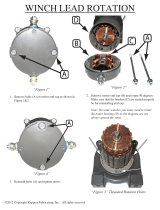
Power Lift Winch Installation
1.Bolt the power winch fully assembled to the
power lift winch support, either a 2" x 8"
[50 x 200 mm] board that will span at least
three (3) rafters or a 3/8" [9.5 mm] thick
steel plate welded to two (2) angle iron
pieces each long enough to span at least two
(2) rafters, using 5/16-18 supplied
hardware. The brake mechanism will
extend toward one side.
Install a cable hook, supplied in
hardware package, between the
mounting bolt and power winch frame
as shown in Figure 11.
2.Attach the power lift winch support
(with the winch secured) to the ceiling at
the center of the feeder line, see Figure
12. The winch support must be parallel
to the feeder line and must span at least
three (3) rafters in a wood frame house
and two (2) rafters in a steel frame
house.
3.
Figure 7. Welded Steel Truss Ceiling Bracket Installation
Weld
Here
Cable Travel
Weld
Here
Figure 8. Wood Truss Ceiling Bracket Installation
Secure ceiling hook to truss using 1/4-20
lag bolt through large center hole.
Cable Travel
Figure 9. Pulley Installation
Wood Truss
Ceiling Hook
1/4" Lag Bolt
Swivel Pulley
Drop Cable
1255-115 2/2001
Angle Iron
3/8" [9.5 mm]
Thick Steel Plate
Figure 10. Optional Power Lift Winch Support detail
4) 5/16-18 Bolt,
Washer, and
Lock Nut
2) Cable Hook
1) Power Lift Winch
3) Power Lift
Winch Support
1255-79 1/2001
Figure 11. Assemble the Power Winch to the winch support

Installing the Suspension System GENESIS® FEEDING SYSTEM
14
MF2322 D
If the boot is located at the center of the feeder line, locate the power winch a few feet offset from the center
of the feeder line. However, the winch drum must be directly in line with where the main cable is to be
installed.
Figure 12. Mounting the Power Lift Winch and Support to the rafters
Installing the Main Winch Cable
1.Extend the 3/16" [5 mm] main winch cable
the full length of the feeder line. Attach the
cable temporarily to the ceiling with nails,
staples, or some type of fastener. Figure 13.
shows a double back arrangement for feed
lines over 350’ [107 m].
2.Route the cable through the winch drum
relief located near the bottom of the drum.
Tighten the set screw to anchor the cable to
the drum, see Figure 14.
3.Turn the winch drum one full revolution.
Guide the cable against the flange at the
bottom of the winch drum. The cable must
not wrap over itself on the drum but should
be wrapped as close as possible to each
previous wrap, see Figure 15.
Drop Installation
The suspension systems are based on a ceiling height of 14’ [4.3 m] with suspension drop points every 8’ [2.4
m]. DO NOT EXCEED 10’ [3 m] BETWEEN SUSPENSION DROPS.
IMPORTANT: Adequate overhead structure must be provided to support the weight of the
feeders, feed drops, power units, etc. Special support is required at power unit and
feeder boot locations.
1) Power Lift
Winch Support
2) Rafte
r
Figure 13. Double back arrangement, feed lines
over 350’ [107 m]
1255-63 4/2001
Double Clamp these areas
Figure 14. Attach cable to winch
1255-80 1/2001
1) Winch Drum Relie
f
with Set Screw
2) 3/16" Main
Winch Cable
3) Drum Direction
of Rotation
Figure 15. Attach cable to winch

GENESIS® FEEDING SYSTEM Installing the Suspension System
MF2322 D
15
The feeder line must be supported within 3’ [0.9 m]
of the power unit. This is in addition to the
required power unit suspension. If the control pan
or feeder boot does not come out directly under a
truss, fasten a pulley to a 2" x 8" [50 x 200 mm]
board or steel angle iron that will span two (2)
trusses and is capable of supporting 300 lbs [136
kg] for the feeder boot and 75 lbs [34 kg] for the
control pan.
1.Attach a 3004 pulley to each hook or ceiling bracket.
2.Thread the end of the 3/32" [2.3 mm] or 1/8" [3.2
mm] cable through the pulley toward the winch.
Clamp this end to the 3/16" [5 mm] winch cable about
6" [150 mm] from the last pulley using a 3/16" cable
clamp, see Figure 17.
Figure 17. Drop Installation
3.Allow enough cable length for installation to the feeder line and to the adjustment leveler. Sufficient cable is
included to provide "throwbacks" on drops located beneath and near the winch. Figure 18. shows a
"throwback" cable arrangement.
Figure 18. "Throwback" cable arrangement
4.Begin installing suspension drops at the winch and proceed to the ends of the feeder line.
Keep the main cable tight between drops. It may be necessary to hang a weight on the end of the main cable
to maintain tension.
Figure 16. Feeder boot suspension.
Feeder Boot
Suspension
Screw Hook Opening
Cable Pull
3/32" Drop Cable
3/16" Winch Cable
Wood Truss
Ceiling Hook
1/4" Lag Bolt
Swivel Pulley
Drop Cable
967-4 2/01

BREEDER Feeder Pan Assembly GENESIS® FEEDING SYSTEM
16
MF2322 D
BREEDER Feeder Pan Assembly
Locate the parts shown in the Photo below.
1
2
3
4
5
6
7
8
9
ITEM PART NO. DESCRIPTION
1 50339 GENESIS GRILL
2 50337 ADJUSTABLE GRILL
3 51774 SLIDE LOCK
4 51862 FEED CHUTE
5 50340 SUPPORT CAP
6 50338 ADJUSTMENT KNOB
7 50341 HEIGHT RING
8 50457 FEED CONE
9 50342 GENESIS PAN

GENESIS® FEEDING SYSTEM BREEDER Feeder Pan Assembly
MF2322 D
17
Feed Pan Assembly Box Construction
Chore-Time recommends building an assembly box to aid in assembling the feeder pans
Figure 19. Feed Pan Assembly Box Construction
To build the assembly box use a 17" [432 mm] x 24" [609 mm] piece of plywood, two (2) 14" [356 mm] and two
(2) 22" [584 mm] long pieces of 2" [51 mm] x 6" [236 mm] boards.
1.Cut a piece of 3/4" [19 mm] plywood 17"[432 mm] x 24"[609 mm].
2.Center the grill on the 17"[432 mm] x 24"[609 mm] piece of plywood. Use a pencil and draw around the
inside edge of the grill as shown in Figure 19. Mark a "V" at each strut location.
3.Remove the grill.
4.Use a spade bit to drill a hole at each strut location as shown in Figure 19.
5.Use a sabre saw to cut along the line.
6.Use FOUR (4) 21"[534 mm] and two (2) 48"[1219 mm] 2" [51 mm] x 6" [236 mm] to construct the box
sides. Nail the 3/4" [19 mm] plywood fixture to the box.
It is important to use 6" [152 mm] sides for the box. Smaller BOARD will not allow sufficient depth for the
grill to be placed in the box face down.
FROM A 3/4" PIECE OF PLYWOOD. CUT A 17" X 24" PLYWOOD TOP. MARK THE CEN-
TER OF THE TOP. MARK TWO 12.25" CIRCLES 3" OFF CENTER.
MAKE TWO ASSEMBLY TOPS
CUT THE TWO 12.25" CIRCLES. WITH THE CUT OUT REMOVED. PLACE A GRILL IN
THE OPENING. MARK THE OPENING NEEDED TO ALLOW THE GRILL TO REST ON
THE PLYWOOD TOP.
MAKE A 2 X 6 FRAME TO FIT UNDER THE TWO TOPS. LEAVE A SPACE BETWEEN
THE TOP TOO USE FOR PART STORAGE
CUT

BREEDER Feeder Pan Assembly GENESIS® FEEDING SYSTEM
18
MF2322 D
BREEDER Pan Assembly Procedure
The following procedure includes all possible components for this feeder. If your installation does not
include one of the components skip over it and go to the next step.
1.Place a grill in the pan assembly box fixture.
2.Install two (2) adjustable grills. Make sure to line up the
arrows on the teeth for proper installation see Figure
21.
Tip: Prior to installing the adjustable
grills align the teeth as shown
in Figure 21. Hold the grills
together at the teeth and
press them through the snaps
as shown in Figure 21.
Figure 20. Place Grill into Assembly Fixture
Figure 21. Install adjustable grills
Align teeth on adjustable grills as
shown below.

GENESIS® FEEDING SYSTEM BREEDER Feeder Pan Assembly
MF2322 D
19
3.Install two (2) feed cones see Figure 22..
4.Install the feeder pan.
5.Remove pan assembly from the assembly
fixture.
6. WHEN SNAPING PAN INTO GRILL BE
SURE THAT ALL RETAINER POST IN
THE PAN ARE INSIDE LOWER RING ON
ADJUSTABLE GRILLS
Figure 22. Install feed cones
Feed Cone
Push down
Place arms
through grill
SET TO #2
Figure 23. Install Feeder pan
SNAP PAN HINGE INTO
GRILL
RETAINER POST
PAN SNAPS

BREEDER Feeder Pan Assembly GENESIS® FEEDING SYSTEM
20
MF2322 D
Feeder Pan and Tube Assembly Fixture Construction
Chore-Time recommends building an assembly fixture to aid installation of the feed pans to the feeder tube.
Figure 24. Feeder Pan and Tube Assembly Fixture Construction
SEE GENESIS FEED TUBE SPACING ON PAGE 23
FOR THE “X” DIMENSION.
SPACING DIMENSIONS
2” X 4” X 21”
SUGGESTED BOTTOM FOR
PARTS HOLDING SHELF.
/