Page is loading ...

®
PROJECTIONLINK
TM
PL-300, PL-300E, AND BNDL-001
PRESENTATION SOLUTIONS
Projector Accessories
®
www.proxima.com
1.800.294.6400
PROJECTIONLINK
[ User & Installation Guide ]

ii ProjectionLink User & Installation Guide
Warranty
Proxima Corp. (“Proxima”) warrants that each ProjectionLink
system (Product) purchased from Proxima Corp. is free from defects
in materials and workmanship under normal use during the
warranty period said warranty shall commence on the day of
purchase by the End-User and continue for a period of two (2)
years.
To exercise the End-User’s rights under this warranty, the Product
must be returned at the End-User’s expense, to Proxima
Corporation or to any authorized Proxima Corp. service center. The
returned product must be accompanied by (i) the End-User’s sales
receipt or invoice that shows the date of sale, product type and
dealer’s name, and, when returned to Proxima Corporation, (ii) a
return authorization number, issued by Proxima Corporation that is
clearly displayed on the outside of the shipping carton. The
Warranty extends only to the original End-User purchase and is not
transferable.
During the Warranty Period, Proxima Corp. will, at no additional
charge, repair or replace defective parts or, at the option of Proxima
Corporation, replace the entire unit. Proxima Corporation shall have
no other obligation, and repair or replacement shall be the End-
User’s exclusive remedy for any defect in the Product.
This Limited warranty does not extend to any Product that has been
damaged due to accident, unauthorized modifications, tampering,
abuse, misuse, alterations, unusual physical or electrical stress, or to
any Product that has been serviced by other than Proxima
Corporation or its authorized agents or which has been used in any
manner other than from ordinary use in the application for which it
was intended. This limited warranty does not extend, or apply, to
any other products which may be connected to Product.
THE FOREGOING WARRANTY IS EXPRESSLY IN LIEU OF ANY
OTHER EXPRESS OR IMPLIED WARRANTIES, INCLUDING,
WITHOUT LIMITATION, WARRANTIES OF MERCHANTABILITY
OR FITNESS FOR A PARTICULAR PURPOSE. TO THE EXTENT

ProjectionLink User & Installation Guide iii
NOT PROHIBITED BY LAW, ALL STATUTORY WARRANTIES
ARE HEREBY WAIVED AND EXCLUDED FROM THIS LIMITED
WARRANTY. PROXIMA CORPORATION EXPRESSLY
DISCLAIMS ALL WARRANTIES NOT STATED IN THE LIMITED
WARRANTY.
It is understood and agreed that the liability of Proxima Corporation,
whether in contract, in tort, under any warranty, in negligence or
otherwise shall not exceed the return of the amount of the purchase
price paid by the End-User and under no circumstances shall
Proxima Corporation be liable for special, indirect or consequential
damages. No action, regardless of form, arising out of the agreement
to purchase the Product may be brought by the End-User more than
one year after the cause of the action has accrued.

iv ProjectionLink User & Installation Guide
This page intentionally left blank.

ProjectionLink User & Installation Guide v
Table of Contents
Chapter 1:
What is ProjectionLink?.......................................... 1
ProjectionLink Operational Summary........................ 3
Understanding the ProjectionLink System ................ 4
What’s in the PL-300/PL-300E Accessories Box?........ 5
What’s in the BNDL-001 Accessories Box?................. 7
RS-232 Control Cables ............................................... 8

vi ProjectionLink User & Installation Guide
Chapter 2:
Installing ProjectionLink......................................... 9
Before Installing ........................................................ 9
Connecting the External PL-300 Receiver................ 10
To the DP6850 and DP6850+ ........................................................... 12
To the DP9240, DP9260, and DP9260+ ...........................................13
To the Pro AV 9320, Pro AV 9400, Pro AV 9400+, and
Pro AV 9410.......................................................................................14
To the Pro AV 9350............................................................................15
To the LX2 and LS2 ...........................................................................17
To the DP9280 ...................................................................................18
To the DP6150 ...................................................................................19
To the S520........................................................................................20
Connecting to the Advanced Connectivity Module 21
Configuring the Transmitter.................................... 22
Connecting the Transmitter.................................................................23
Connecting Input Sources...................................................................25
Connecting Local Outputs ..................................................................26
Connecting CAT-5 Cable .......................................... 27
Chapter 3:
Configuring ProjectionLink .................................. 29
Fine-Tuning the Image............................................. 32
Chapter 4:
Mounting ProjectionLink ..................................... 35
Mounting the Transmitter Under a Table................ 35
Mounting the Transmitter in a Rack........................ 37
Mounting the Receiver ............................................ 38

Table of Contents
ProjectionLink User & Installation Guide vii
Chapter 5:
Using ProjectionLink ............................................ 39
Switching Between Input Sources........................... 39
Using ProjectionLink with an IR Remote Control .... 41
Chapter 6:
Upgrading ProjectionLink Firmware .................... 43
Appendix A:
Troubleshooting................................................... 45
Troubleshooting Table............................................. 46
Technical Support .................................................... 48
Appendix B:
Technical Specifications ....................................... 49
Appendix C:
Dip-Switch Settings.............................................. 51
Appendix D:
Operational Summary .......................................... 53

viii ProjectionLink User & Installation Guide
This page intentionally left blank.

ProjectionLink User & Installation Guide 1
Chapter 1:
What is ProjectionLink?
ProjectionLink is Proxima’s revolutionary new solution to
numerous stray cables to simplify projector installations and
connectivity. It’s the first single-wire solution that connects
your computer and video sources with an installed projector.
Utilizing Category 5 (CAT-5) unshielded, twisted pair cabling,
installing and configuring your installed projector is as easy as
pulling a network cable.

2 ProjectionLink User & Installation Guide
The Projection Link System
ProjectionLink includes two components: a Transmitter
(PL-300T) and a Receiver (PL-300R). The Transmitter is con-
nected to your computer or other source and the Receiver is
connected to your projector.
This Installation Guide shows you how to configure Projec-
tionLink. This Installation Guide does not explain how to
install ceiling mount projectors or how to pull cable, etc. Use
the suggestions in this Installation Guide to help configure
your projector with the ProjectionLink system.
The ProjectionLink Transmitter (PL-300T) should be located
somewhere in your conference room or boardroom. The
Transmitter allows you to connect multiple input sources to
your projector via CAT-5 cabling. Typically, the Transmitter is
located under your conference table or inside a podium at the
front of a room. This is the connection point for your input
devices (computers, video, and audio devices) and your
installed projector.
Transmitter
TransmitterTransmitter
Transmitter
Receiver
ReceiverReceiver
Receiver

What is ProjectionLink?
ProjectionLink User & Installation Guide 3
ProjectionLink Operational
Summary
ProjectionLink can be controlled by either manually selecting
the input on the Transmitter (Push Button Operation) or
selecting the input on the Projector’s Remote. Depending on
the projector connected to ProjectionLink, you may have
limited operational functionality. The tables contained in
“Appendix D: Operational Summary” on page 53 summarize
ProjectionLink’s operational functionality when connected
with various Proxima projectors.

Understanding the ProjectionLink System
4 ProjectionLink User & Installation Guide
Understanding the
ProjectionLink System
The ProjectionLink system offers many advantages over previ-
ous mounted projection systems. It also has a few limitations
you should be aware of. The following tables lists some fea-
tures the ProjectionLink system can and cannot do:
Your ProjectionLink system
will:
Your ProjectionLink system
will not:
Eliminate the need for expensive
coaxial cables and amplifiers
Facilitate high-bandwidth appli-
cations (greater than 140 MHz)
Conveniently switch between
presentation devices (e.g., com-
puter to video)
Replace a matrix switcher
Reduce installation time Replace a distribution amplifier
Allow RS-232 control from
external control systems such as
Crestron or AMX/Panja
Encode or decode video signals
Easily connect your installed
projector to your presentation
devices
Accept multiple video signals on
each video input
Increase the number of com-
puter and/or video inputs on
your projector
Support Picture-in-Picture since
only one video signal at a time is
sent to the projector
Accept HDTV component (Y,
Pb, Pr) video

What is ProjectionLink?
ProjectionLink User & Installation Guide 5
What’s in the PL-300/PL-
300E Accessories Box?
Make sure that all of the items with the associated part number
(P/N) listed below are included in your packaging:
VGA Cable
VGA CableVGA Cable
VGA Cable
Two-mete r
Two-mete rTwo-mete r
Two-mete r
Mini-jack Cable
Mini-jack CableMini-jack Cable
Mini-jack Cable
S-video Cable
S-video CableS-video Cable
S-video Cable
Two -me ter
Two -me terTwo -me ter
Two -me ter
Two - me t er
Two - me t erTw o- me t er
Two - me t er
(900-95106-3)
(900-95106-3)(900-95106-3)
(900-95106-3) (900-95109)
(900-95109)(900-95109)
(900-95109)
(900-46606)
(900-46606)(900-46606)
(900-46606)
Composite Video
Composite VideoComposite Video
Composite Video
Two -me ter
Two -me terTwo -me ter
Two -me ter
(900-49706)
(900-49706)(900-49706)
(900-49706)
Cable
Cable Cable
Cable
Component
ComponentComponent
Component
Two - me t er
Two - me t erTwo - me t er
Two - me t er
(900-95205)
(900-95205)(900-95205)
(900-95205)
to RCA Cable
to RCA Cableto RCA Cable
to RCA Cable
9-pin RS-232 Cable
9-pin RS-232 Cable9-pin RS-232 Cable
9-pin RS-232 Cable
(900-95212)
(900-95212)(900-95212)
(900-95212)
Two-meter 15 pin to
Two-meter 15 pin toTwo-meter 15 pin to
Two-meter 15 pin to
Two-meter 9-pin to
Two-meter 9-pin to Two-meter 9-pin to
Two-meter 9-pin to
User’s Guide
User’s GuideUser’s Guide
User’s Guide
Two 9-Volt AC
Two 9-Volt AC Two 9-Volt A C
Two 9-Volt AC
1-Amp Power Adapters
1-Amp Power Adapters 1-Amp Power Adapters
1-Amp Power Adapters
9-pin RS-232 Cable
9-pin RS-232 Cable9-pin RS-232 Cable
9-pin RS-232 Cable
(900-95207 US)
(900-95207 US)(900-95207 US)
(900-95207 US)
(010-0294-00)
(010-0294-00)(010-0294-00)
(010-0294-00)
(900-95209)
(900-95209)(900-95209)
(900-95209)
(900-95208 Europe)
(900-95208 Europe)(900-95208 Europe)
(900-95208 Europe)

What’s in the PL-300/PL-300E Accessories Box?
6 ProjectionLink User & Installation Guide
Additional parts are also included for mounting. These parts
are the:
• Table Mounting Bracket (140-01610)
• Rack Mounting Bracket (140-01611)
• Receiver Ceiling Mount Bracket (140-01612)
• Hardware Mounting Kit (080-03028) that contains:
• U-bolt assembly that includes the u-bolt, flat plate, and two
hex nuts
• eight 8 mm screws
• four #10-32 screws
Two-meter Mini-jack
Two-meter Mini-jackTwo-meter Mini-jack
Two-meter Mini-jack
to RCA Audio Cable
to RCA Audio Cableto RCA Audio Cable
to RCA Audio Cable
(900-95210)
(900-95210)(900-95210)
(900-95210)
Six-inch 9-pin to
Six-inch 9-pin toSix-inch 9-pin to
Six-inch 9-pin to
MiniDin 8 Cable
MiniDin 8 CableMiniDin 8 Cable
MiniDin 8 Cable
(301113)
(301113)(301113)
(301113)

What is ProjectionLink?
ProjectionLink User & Installation Guide 7
What’s in the BNDL-001
Accessories Box?
Make sure that all of the items with the associated part number
(P/N) listed below are included in your packaging:
User’s Guide
User’s GuideUser’s Guide
User’s Guide
One 9-Volt AC
One 9-Volt AC One 9-Volt AC
One 9-Volt AC
1-Amp Power Adapter
1-Amp Power Adapter 1-Amp Power Adapter
1-Amp Power Adapter
(010-0294-00)
(010-0294-00)(010-0294-00)
(010-0294-00)
(900-95207 US)
(900-95207 US)(900-95207 US)
(900-95207 US)
100-Foot Category-5
100-Foot Category-5100-Foot Category-5
100-Foot Category-5
Unshielded Twisted
Unshielded TwistedUnshielded Twisted
Unshielded Twisted
Pair Cable
Pair CablePair Cable
Pair Cable
(210-0209-00)
(210-0209-00)(210-0209-00)
(210-0209-00)
VGA Cable
VGA CableVGA Cable
VGA Cable
Two - me t er
Two - me t erTw o- me t er
Two - me t er
(900-95106-3)
(900-95106-3)(900-95106-3)
(900-95106-3)
Two-meter 9-pin to
Two-meter 9-pin to Two-meter 9-pin to
Two-meter 9-pin to
9-pin RS-232 Cable
9-pin RS-232 Cable9-pin RS-232 Cable
9-pin RS-232 Cable
(900-95209)
(900-95209)(900-95209)
(900-95209)
Two-meter Mini-jack
Two-meter Mini-jackTwo-meter Mini-jack
Two-meter Mini-jack
to RCA Audio Cable
to RCA Audio Cableto RCA Audio Cable
to RCA Audio Cable
(900-95210)
(900-95210)(900-95210)
(900-95210)

RS-232 Control Cables
8 ProjectionLink User & Installation Guide
Additional parts are also included for mounting. These parts
are the:
• Table Mounting Bracket (140-01610)
• Rack Mounting Bracket (140-01611)
• Hardware Mounting Kit (505-1043-00) that contains:
• eight 8 mm screws
• four #10-32 screws
RS-232 Control Cables
All cables required for various configurations are included with
ProjectionLink. However, you will only need a few of these
cables to make your actual connections. The following table
lists which cables are needed for RS-232 control:
Projector Cable(s) required Part
Number
(P/N)
Provided with
X350 N/A N/A
S520
HD15 to DB9 (15-pin to 9-pin) 900-95212 ProjectionLink
LX2, LS2
MiniDin8 to DB9 (8-pin to 9-pin) 900-95190 Projector
DP6150
9-pin to MiniDin
MiniDin8 to MiniDin8 (8-pin to 8-pin)
301.113
301.102
ProjectionLink
Projector
DP6850, DP6850+
HD15 to DB9 (15-pin to 9-pin) 900-95212 ProjectionLink
DP9240, DP9260,
DP9260+
MiniDin8 to DB9 (8-pin to 9-pin) 900-95190 Projector
Pro AV 9320,
Pro AV 9350
DB9 to DB9 RS-232 cable (9-pin to
9-pin)
900-95209 ProjectionLink
DP9280
MiniDin8 to DB9 (8-pin to 9-pin) 900-95190 Projector
Pro AV 9400,
Pro AV 9400+,
Pro AV 9410
DB9 to DB9 RS-232 cable (9-pin to
9-pin)
900-95209 ProjectionLink

ProjectionLink User & Installation Guide 9
Chapter 2:
Installing ProjectionLink
Installing ProjectionLink involves making connections
between your projector, transmitter, and receiver. These con-
nections are different based on the projector you are using
with ProjectionLink. Be sure to use the connections for your
particular unit.
Before Installing
Make sure to do the following prior to installing Projection-
Link:
1. Make sure you understand how to work with installed
projector applications. This Installation Guide only helps
configure a projector with the ProjectionLink system. For
help with projector installation, contact a Proxima sales
engineer.

Connecting the External PL-300 Receiver
10 ProjectionLink User & Installation Guide
2. Connect a computer source directly to your projector, ver-
ify the image quality, and make any adjustments.
Connecting the External
PL-300 Receiver
Before installing the receiver and cabling, we recommend you
test the cable and connections. This enables you to easily
make any adjustments to the receiver. It may be necessary to
match the receiver to the length of cable used in the installa-
tion. See “Connecting CAT-5 Cable” on page 27 for more
information.
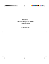
The receiver has the following ports:
ProjectionLink receiver
1
11
12
22
23
33
34
44
47
77
76
66
6
5
55
5

Installing ProjectionLink
ProjectionLink User & Installation Guide 11
The receiver ports function as follows:
PORT CONNECTS…
1 Computer video from the receiver to the projector.
2 Computer stereo audio from the receiver to the projector.
3 Composite video from the receiver to the projector.
4 S-video from the receiver to the projector.
5 Video stereo audio from the receiver to the projector.
6 Component video from the receiver to the projector.
7 RS-232 control from the receiver to the projector.

Connecting the External PL-300 Receiver
12 ProjectionLink User & Installation Guide
To the DP6850 and DP6850+
Use the following illustration as a guide for connecting the
receiver to the DP6850 and DP6850+:
See “Appendix D: Operational Summary” on page
53 for an operational summary. It is only possible to
connect one type of video input at a time. You
cannot connect an S-video and a composite video
source at the same time. Choose either S-video or
composite video for your input source.
12
12
AUDIO IN
AUDIO
OUT
RGB IN
RGB OUT
CONTROL
USB
VIDEO IN
S-VIDEO IN
AUDIO IN
MONO
Video
Cable
S-Video Cable
RS232 Control Cable
VGA
Cable
Video Audio Cable
Computer
Audio
Cable
/