Page is loading ...

VDSL Switch-VS2512A
VDSL Splitter-VM2524
VDSL Splitter-VM2548
Installation Guide


Installation Guide
VDSL Switch-VS2512A
VDSL Switch supporting 12 VDSL Lines, with 1 Slot for Optional Gigabit
Uplink, 10/100BASE-TX, or 100BASE-FX Modules
VDSL Splitter-VM2524
VDSL Splitter supporting 24 VDSL Lines
VDSL Splitter-VM2548
VDSL Splitter supporting 48 VDSL Lines

Accton is a trademark of Accton Technology Corporation. Other trademarks or brand names mentioned
herein are trademarks or registered trademarks of their respective companies.
International Headquarters
No. 1 Creation Road III,
Science-based Industrial Park
Hsinchu 300, Taiwan
Phone: +886-3-5770-270
Fax: +886-3-5770-267
Internet: support@accton.com.tw
Europe Headquarters
Edificio Conata II,
Calle Fructuós Gelabert 6-8, 2
o
, 4
a
,
08970 - Sant Joan Despí,
Barcelona, Spain.
Phone: +34-93-477-4920
Fax: +34-93-477-3774
Asia Pacific Headquarters
1 Claymore Drive
#08-05/06 Orchard Towers (Rear Block)
Singapore 229594
Phone: +65 238 6556
Fax: +65 238 6466
Internet: www.acctontech.com
Copyright © 2002 by Accton Technology Corporation. All rights reserved.
No part of this document may be copied or reproduced in any form or by any means without the prior written
consent of Accton Technology Corporation.
Accton makes no warranties with respect to this documentation and disclaims any implied warranties of
merchantability, quality, or fitness for any particular purpose. The information in this document is subject to
change without notice. Accton reserves the right to make revisions to this publication without obligation to
notify any person or entity of any such changes.
VS2512A
VM2524
VM2548
E072002-R01
150000010100A

Accton Technology Corporation
Limited Warranty: Accton warrants all its products to be free of manufacturing defects in
workmanship and materials, under normal use and service, for the applicable warranty
term. All Accton products carry a standard 90-day limited warranty from the date of
purchase from Accton or its Authorized Reseller. Accton may, at its own discretion, repair
or replace any product not operating as warranted with a similar or functionally equivalent
product, during the applicable warranty term.
The standard limited warranty can be upgraded to a Limited Lifetime* warranty by
registering new products within 30 days of purchase from Accton or its Authorized
Reseller. Registration can be accomplished via the enclosed product registration card or
online via the Accton web site. Failure to register will not affect the standard limited
warranty. The Limited Lifetime warranty covers a product during the Life of that Product,
which is defined as the period of time during which the product is an “Active” Accton
product. A product is considered to be “Active” while it is listed on the current Accton price
list. As new technologies emerge, older technologies become obsolete and Accton will, at
its discretion, replace an older product in its product line with one that incorporates these
newer technologies. At that point, the obsolete product is discontinued and is no longer
an “Active” Accton product. A list of discontinued products is attached with the most
recent version being available on the support section of our web site
(http://www.acctontech.com
).
All products that are replaced become the property of Accton. Replacement products may
be either new or reconditioned. Any replaced or repaired product carries either a 30-day
limited warranty or the remainder of the initial warranty, whichever is longer. Accton is not
responsible for any custom software or firmware, configuration information, or memory
data of Customer contained in, stored on, or integrated with any products returned to
Accton pursuant to any warranty. Products returned to Accton should have any
customer-installed accessory or add-on components, such as expansion modules,
removed prior to returning the product for replacement. Accton is not responsible for
these items if they are returned with the product.
Customers must contact Accton for a Return Material Authorization number prior to
returning any product to Accton. Proof of purchase may be required. Any product
returned to Accton without a valid Return Material Authorization (RMA) number clearly
marked on the outside of the package will be returned to customer at customer’s
expense. Customers are responsible for all shipping charges from their facility to Accton.
Accton is responsible for return shipping charges from Accton to customer.

Limited Warranty
WARRANTIES EXCLUSIVE: IF AN ACCTON PRODUCT DOES NOT OPERATE AS
WARRANTED ABOVE, CUSTOMER'S SOLE REMEDY SHALL BE REPAIR OR
REPLACEMENT OF THE PRODUCT IN QUESTION, AT ACCTON’S OPTION. THE
FOREGOING WARRANTIES AND REMEDIES ARE EXCLUSIVE AND ARE IN LIEU OF
ALL OTHER. WARRANTIES OR CONDITIONS, EXPRESS OR IMPLIED, EITHER IN
FACT OR BY OPERATION OF LAW, STATUTORY OR OTHERWISE, INCLUDING
WARRANTIES OR CONDITIONS OF MERCHANTABILITY AND FITNESS FOR A
PARTICULAR PURPOSE. ACCTON NEITHER ASSUMES NOR AUTHORIZES ANY
OTHER PERSON TO ASSUME FOR IT ANY OTHER LIABILITY IN CONNECTION
WITH THE SALE, INSTALLATION, MAINTENANCE OR USE OF ITS PRODUCTS.
ACCTON SHALL NOT BE LIABLE UNDER THIS WARRANTY IF ITS TESTING AND
EXAMINATION DISCLOSE THE ALLEGED DEFECT IN THE PRODUCT DOES NOT
EXIST OR WAS CAUSED BY CUSTOMER'S OR ANY THIRD PERSON'S MISUSE,
NEGLECT, IMPROPER INSTALLATION OR TESTING, UNAUTHORIZED ATTEMPTS
TO REPAIR, OR ANY OTHER CAUSE BEYOND THE RANGE OF THE INTENDED
USE, OR BY ACCIDENT, FIRE, LIGHTNING, OR OTHER HAZARD.
LIMITATION OF LIABILITY: IN NO EVENT, WHETHER BASED IN CONTRACT OR
TORT (INCLUDING NEGLIGENCE), SHALL ACCTON BE LIABLE FOR INCIDENTAL,
CONSEQUENTIAL, INDIRECT, SPECIAL, OR PUNITIVE DAMAGES OF ANY KIND, OR
FOR LOSS OF REVENUE, LOSS OF BUSINESS, OR OTHER FINANCIAL LOSS
ARISING OUT OF OR IN CONNECTION WITH THE SALE, INSTALLATION,
MAINTENANCE, USE, PERFORMANCE, FAILURE, OR INTERRUPTION OF ITS
PRODUCTS, EVEN IF ACCTON OR ITS AUTHORIZED RESELLER HAS BEEN
ADVISED OF THE POSSIBILITY OF SUCH DAMAGES.
SOME COUNTRIES DO NOT ALLOW THE EXCLUSION OF IMPLIED WARRANTIES
OR THE LIMITATION OF INCIDENTAL OR CONSEQUENTIAL DAMAGES FOR
CONSUMER PRODUCTS, SO THE ABOVE LIMITATIONS AND EXCLUSIONS MAY
NOT APPLY TO YOU. THIS WARRANTY GIVES YOU SPECIFIC LEGAL RIGHTS,
WHICH MAY VARY FROM STATE TO STATE. NOTHING IN THIS WARRANTY SHALL
BE TAKEN TO AFFECT YOUR STATUTORY RIGHTS.
* Accton will provide warranty service for up to three years following discontinuance from
the active Accton price list. Under the limited lifetime warranty, internal and external
power supplies, fans, and cables are covered by a standard one-year warranty from date
of purchase

i
Compliances
FCC - Class A
This equipment generates, uses, and can radiate radio frequency energy and, if not
installed and used in accordance with the instruction manual, may cause interference to
radio communications. It has been tested and found to comply with the limits for a Class A
computing device pursuant to Subpart B of Part 15 of FCC Rules, which are designed to
provide reasonable protection against such interference when operated in a commercial
environment. Operation of this equipment in a residential area is likely to cause
interference, in which case the user, at his own expense, will be required to take whatever
measures may be required to correct the interference. You are cautioned that changes or
modifications not expressly approved by the party responsible for compliance could void
your authority to operate the equipment.
You may use unshielded twisted-pair (UTP) for RJ-45 connections - Category 3 or greater
for 10 Mbps connections, and Category 5 for 100 Mbps connections. For fiber optic
connections, you may use 50/125 or 62.5/125 micron multimode fiber or 9/125 micron
single-mode fiber.
Warnings: 1. Wear an anti-static wrist strap or take other suitable measures to prevent
electrostatic discharge when handling this equipment.
2. When connecting this hub to a power outlet, connect the field ground lead
on the tri-pole power plug to a valid earth ground line to prevent electrical
hazards.
Industry Canada - Class A
This digital apparatus does not exceed the Class A limits for radio noise emissions from
digital apparatus as set out in the interference-causing equipment standard entitled
“Digital Apparatus,” ICES-003 of the Department of Communications.
Cet appareil numérique respecte les limites de bruits radioélectriques applicables aux
appareils numériques de Classe A prescrites dans la norme sur le matériel brouilleur:
“Appareils Numériques,” NMB-003 édictée par le ministère des Communications.
Japan VCCI Class A

ii
CE Mark Declaration of Conformance for EMI and Safety (EEC)
This information technology equipment complies with the requirements of the Council
Directive 89/336/EEC on the Approximation of the laws of the Member States relating to
Electromagnetic Compatibility and 73/23/EEC for electrical equipment used within certain
voltage limits and the Amendment Directive 93/68/EEC. For the evaluation of the
compliance with these Directives, the following standards were applied:
Warning! Do not plug a phone jack connector in the RJ-45 port. This may damage this
device. Les raccordeurs ne sont pas utilisé pour le système téléphonique!
Taiwan BSMI Class A
RFI Emission: • Limit class A according to EN 55022:1998
• Limit class A for harmonic current emission according to EN 61000-3-2/1995
• Limitation of voltage fluctuation and flicker in low-voltage supply system
according to EN 61000-3-3/1995
Immunity: • Product family standard according to EN 55024:1998
• Electrostatic Discharge according to EN 61000-4-2:1995
(Contact Discharge: ±4 kV, Air Discharge: ±8 kV)
• Radio-frequency electromagnetic field according to EN 61000-4-3:1996
(80 - 1000 MHz with 1 kHz AM 80% Modulation: 3 V/m)
• Electrical fast transient/burst according to EN 61000-4-4:1995 (AC/DC power
supply: ±1 kV, Data/Signal lines: ±0.5 kV)
• Surge immunity test according to EN 61000-4-5:1995
(AC/DC Line to Line: ±1 kV, AC/DC Line to Earth: ±2 kV)
• Immunity to conducted disturbances, Induced by radio-frequency fields:
EN 61000-4-6:1996 (0.15 - 80 MHz with 1 kHz AM 80% Modulation: 3 V/m)
• Power frequency magnetic field immunity test according to
EN 61000-4-8:1993
(1 A/m at frequency 50 Hz)
• Voltage dips, short interruptions and voltage variations immunity test
according to EN 61000-4-11:1994 (>95% Reduction @10 ms, 30%
Reduction @500 ms, >95% Reduction @5000 ms)
LVD: • EN 60950 (A1/1992; A2/1993; A3/1993; A4/1995; A11/1997)

iii
Safety Compliance
Warning: Fiber Optic Port Safety
Avertissment: Ports pour fibres optiques - sécurité sur le plan optique
Warnhinweis: Faseroptikanschlüsse - Optische Sicherheit
Underwriters Laboratories Compliance Statement
Important! Before making connections, make sure you have the correct cord set. Check
it (read the label on the cable) against the following:
The unit automatically matches the connected input voltage. Therefore, no additional
adjustments are necessary when connecting it to any input voltage within the range
marked on the rear panel.
When using a fiber optic port, never look at the transmit laser while it is
powered on. Also, never look directly at the fiber TX port and fiber cable
ends when they are powered on.
Ne regardez jamais le laser tant qu'il est sous tension. Ne regardez
jamais directement le port TX (Transmission) à fibres optiques et les
embouts de câbles à fibres optiques tant qu'ils sont sous tension.
Niemals ein Übertragungslaser betrachten, während dieses
eingeschaltet ist. Niemals direkt auf den Faser-TX-Anschluß
und auf die Faserkabelenden schauen, während diese
eingeschaltet sind.
Operating Voltage Cord Set Specifications
120 Volts UL Listed/CSA Certified Cord Set
Minimum 18 AWG
Type SVT or SJT three conductor cord
Maximum length of 15 feet
Parallel blade, grounding type attachment plug rated 15 A, 125 V
240 Volts (Europe only) Cord Set with H05VV-F cord having three conductors with
minimum diameter of 0.75 mm
2
IEC-320 receptacle
Male plug rated 10 A, 250 V
CLASS I
LASER DEVICE
DISPOSITIF LASER
DE CLASSE I
LASERGER
DER KLASSE I
ÄT

iv
Wichtige Sicherheitshinweise (Germany)
1. Bitte lesen Sie diese Hinweise sorgfältig durch.
2. Heben Sie diese Anleitung für den späteren Gebrauch auf.
3. Vor jedem Reinigen ist das Gerät vom Stromnetz zu trennen. Verwenden Sie keine
Flüssigoder Aerosolreiniger. Am besten eignet sich ein angefeuchtetes Tuch zur
Reinigung.
4. Die Netzanschlu ßsteckdose soll nahe dem Gerät angebracht und leicht zugänglich sein.
5. Das Gerät ist vor Feuchtigkeit zu schützen.
6. Bei der Aufstellung des Gerätes ist auf sicheren Stand zu achten. Ein Kippen oder Fallen
könnte Beschädigungen hervorrufen.
7. Die Belüftungsöffnungen dienen der Luftzirkulation, die das Gerät vor Überhitzung schützt.
Sorgen Sie dafür, daß diese Öffnungen nicht abgedeckt werden.
8. Beachten Sie beim Anschluß an das Stromnetz die Anschlußwerte.
9. Verlegen Sie die Netzanschlußleitung so, daß niemand darüber fallen kann. Es sollte auch
nichts auf der Leitung abgestellt werden.
10. Alle Hinweise und Warnungen, die sich am Gerät befinden, sind zu beachten.
11. Wird das Gerät über einen längeren Zeitraum nicht benutzt, sollten Sie es vom Stromnetz
trennen. Somit wird im Falle einer Überspannung eine Beschädigung vermieden.
12. Durch die Lüftungsöffnungen dürfen niemals Gegenstände oder Flüssigkeiten in das Gerät
gelangen. Dies könnte einen Brand bzw. elektrischen Schlag auslösen.
13. Öffnen sie niemals das Gerät. Das Gerät darf aus Gründen der elektrischen Sicherheit nur
von authorisiertem Servicepersonal geöffnet werden.
14. Wenn folgende Situationen auftreten ist das Gerät vom Stromnetz zu trennen und von einer
qualifizierten Servicestelle zu überprüfen:
a. Netzkabel oder Netzstecker sind beschädigt.
b. Flüssigkeit ist in das Gerät eingedrungen.
c. Das Gerät war Feuchtigkeit ausgesetzt.
d. Wenn das Gerät nicht der Bedienungsanleitung entsprechend funktioniert oder Sie mit
Hilfe dieser Anleitung keine Verbesserung erzielen.
e. Das Gerät ist gefallen und/oder das Gehäuse ist beschädigt.
f. Wenn das Gerät deutliche Anzeichen eines Defektes aufweist.
15. Zum Netzanschluß dieses Gerätes ist eine geprüfte Leitung zu verwenden. Für einen
Nennstrom bis 6A und einem Gerätegewicht größer 3 kg ist eine Leitung nicht leichter als
H05VV-F, 3G, 0.75 mm
2
einzusetzen.
Der arbeitsplatzbezogene Schalldruckpegel nach DIN 45 635 Teil 1000 beträgt 70 dB(A) oder
weniger.

v
Contents
Chapter 1: About the VDSL Switch-VS2512A 1-1
Overview 1-1
VDSL Technology 1-2
Switch Architecture 1-3
Management Options 1-3
Description of Hardware 1-4
VDSL Switch-VS2512A 1-4
VDSL Splitter-VM2524 and VDSL Splitter-VM2548 1-5
Ethernet-over-VDSL CPE 1-6
Status LEDs 1-7
Optional Media Extender Modules 1-8
Power Supply Receptacle 1-11
Key Features 1-12
Chapter 2: Network Planning 2-1
Introduction to Switching 2-1
Sample Applications 2-1
Internet Connections 2-2
Remote Connections with Fiber Cable 2-2
Making VLAN Connections 2-3
Application Notes 2-4
Chapter 3: Installing the VDSL Switch and Splitter 3-1
Preparing the Site 3-1
Installing Additional Phone Line Equipment 3-1
Equipment Checklist 3-1
Package Contents 3-2
VDSL Switch-VS2512A 3-2
Optional Rack-Mounting Equipment 3-2
Mounting 3-2
Desktop or Shelf Mounting 3-4
Installing an Optional Module into the Switch 3-5
Installing a GBIC Transceiver 3-6
Connecting to the Stack’s Backplane 3-7
Powering On the Switch 3-7
Chapter 4: Making Network Connections 4-1
Twisted-Pair Devices 4-1
Cabling Guidelines 4-1
Connecting to the Punch-down Blocks 4-1
Wiring Closet Connections 4-2
Fiber Optic Devices 4-3

Contents
vi
Appendix A: Troubleshooting A-1
Diagnosing Switch Indicators A-1
Power and Cooling Problems A-1
Installation A-2
In-Band Access A-2
Appendix B: Cables B-1
Specifications. B-1
Twisted-Pair Cable and Pin Assignments B-1
10BASE-T/100BASE-TX Pin Assignments B-2
1000BASE-T Pin Assignments B-3
1000BASE-T Cable Requirements B-3
Cable Testing for Existing Category 5 Cable B-3
Adjusting Existing Category 5 Cabling to Run 1000BASE-T B-4
RJ-21 Port Pin Assignments B-4
Console Port Pin Assignments B-5
DB-9 Port Pin Assignments B-5
Console Port to 9-Pin DTE Port on PC B-5
Console to 25-Pin DTE Port on PC B-5
Appendix C: Specifications C-1
VDSL Switch C-1
Physical Characteristics C-1
Switch Features C-2
Management Features C-3
Standards C-3
Compliances C-3
Warranty C-4
VDSL Splitter C-4
Slide-in Modules C-5
1000BASE-SX Extender Module C-5
1000BASE-LX Extender Module C-5
1000BASE-T Extender Module C-6
100BASE-FX Extender Modules C-6
10/100BASE-TX Extender Modules C-7
1000BASE-X GBIC Module C-7
Appendix D: Ordering Information D-1
Glossary
Index

1-1
Chapter 1: About the VDSL Switch-VS2512A
Overview
Accton’s Ethernet-over-VDSL system consists of end-user CPEs (Customer
Premise Equipment) connected to a VDSL switch and splitter by standard telephone
cable. The VDSL connection delivers an Ethernet data link rated up to
15 Mbps symmetric (full duplex), while simultaneously supporting standard
telephone services. The system can be deployed in any multi-dwelling/multi-tenant
environment (apartment blocks, hotels, or office complex) to provide both high-
speed Internet access and telephone services without any need for re-wiring.
Accton’s VDSL Switch-VS2512A and VDSL-Splitter-VM2524/VM2548 combine both
the data and phone signals coming from your Internet and telephone service
providers, and pass these signals directly over standard telephone wiring to multiple
users in the same building. A CPE is then used to separate these signals and pass
them on to a customer’s computer and telephone equipment. In-building
connections can operate up to 15 Mbps for runs up to 1070 m (3500 ft), 10 Mbps for
runs up to 1220 m (4000 ft), 5 Mbps for runs up to 1525 m (5000 ft).
Note: Category 3 cable must be installed to achieve the maximum distance, but the
distance may be limited by factors such as how the cable is bundled, and the
interference and noise on the link.
The VDSL switch and splitter are typically located in a wiring closet or other central
location of a multi-dwelling/multi-tenant unit, campus or enterprise. An Internet
connection is provided from the ISP to the customer’s building over fiber optic cable,
running Ethernet directly over a 100 Mbps or 1 Gbps connection. This kind of WAN
connection is referred to as Fiber To The Building (FTTB). Phone signals are routed
from PBX/MDF distribution equipment into the splitter. The data and phone signals
for each user are combined in the splitter, and passed over VDSL lines to individual
customers.
The CPE at the other end of the VDSL line connects to any PC or Macintosh
equipped with a 10/100BASE-TX network interface card. Your existing telephone,
modem, or fax machine simply plugs into the CPE’s phone port. There is no need for
special splitters, terminators or filters. In fact, there is no need to modify the home
wiring at all. And, because the VDSL connection is based on Ethernet, no further
complex software configuration is required.

About the VDSL Switch-VS2512A
1-2
VDSL Technology
VDSL (Very High Bit-Rate Digital Subscriber Line) is at the high-end of all the DSL
technologies, offering the best combination of fiber optics and copper to provide
high-speed broadband Internet access. VDSL’s primary application is in providing a
broadband data service to multi-tenant residential or commercial buildings. In this
implementation, fiber optic cable carries data from an Internet Service Provider to
the building; then the installed telephone copper wires take the data and deliver it to
individual units within that building.
Figure 1-1. VDSL Application
VDSL provides high-speed Internet access over existing phone lines by making use
of previously unused frequency bandwidth above the voice band. By placing VDSL
signals above the frequency of the voice signal, a VDSL service can coexist on the
same line as other telephone services. VDSL can operate
symmetrically, providing
the same data rate in both directions, or
asymmetrically, providing
a higher data rate
in the downstream (receive) direction than in the upstream (transmit) direction.
VDSL can deliver high-performance online applications, such as high-quality video
and other switched multimedia services. Accton's Ethernet-over-VDSL system
provides robust performance, with a symmetric data rate up to 15 Mbps, and a range
up to 1525 m (5000 ft). Accton’s system is based on advanced VDSL QAM
(Quadrature Amplitude Modulation) technology with adaptive channel equalization
that overcomes bridge taps and other line distortions. Reed-Solomon Forward Error
Correction and interleaving protects against errors due to impulse noise and enables
recovery from signal interruptions. Frequency Division Duplexing (FDD) separates
downstream and upstream channels and allows VDSL signals to coexist with regular
telephone services. A power back-off mechanism is also implemented to reduce
noise from crosstalk in line bundles.
ISP
(Internet)
Central Office
(PSTN)
Punch Down
Blocks /
Patch Panels
PBX
Telephone/Fax
Telephone
ES2002-TS
VDSL CPE
VDSL
Splitter-VM2524
VDSL
Switch-VS2512A
Telephone Line from Central Office
Fiber Optic Link to ISP
Local Servers
(Locally Hosted Services,
Video Servers, Billing)
Existing Phone
Lines to Clients
Multi-dwelling/Multi-tenant Building
Floor 2
Floor 1
Rooms/Clients
Rooms/Clients
VDSL Lines
L
i
ne
L
i
ne
V
D
SLSpl
it
t
e
r
-
VM252
4
V
D
SLSpl
it
t
e
r
-VM252
4
V
M252
4
V
M252
4
Phone Lines
V
M
2
5
12
A-
4FX-
M
TR
J
-
S
V
M
2
5
12
A-
4FX-
M
TR
J
-
S
1
0
0
B
A
S
E
-
F
X
S
i
n
g
l
e
m
o
d
e
M
o
d
u
l
e
10
0
BASE-
F
X
Singlemo
de
Mod
u
l
e
Ex
p
ansi
o
n
M
odule
V
D
S
LSwi
t
ch
-
VS
25
12A
V
D
S
LSwi
t
ch
-VS
25
12A
R
e
s
e
t
R
es
e
t
P
o
w
e
r
Pow
er
S
t
a
c
k
i
n
g
S
t
a
c
k
ing
D
i
a
g
D
i
a
g
M
a
s
t
e
r
M
as
te
r
O
n
On
O
f
f
O
f
f
U
p
Up
D
o
w
n
D
ow
n
S
t
a
c
k
i
n
g
S
ta
c
k
i
n
g
VS2512A
C
o
n
s
o
l
e
C
ons
ol
e
2
2
3
3
4
4
5
5
6
6
7
7
8
8
9
9
1
0
1
0
11
11
1
2
12
V
D
S
L
V
D
S
L
1
1
A
c
t
i
v
i
t
y
A
cti
vi
ty
L
i
n
k
L
i
n
k
A
c
t
i
v
i
t
y
Acti
v
i
ty
L
i
n
k
/
S
p
e
e
d
L
i
nk
/
S
pe
e
d
1
1
2
2
3
3
4
4
Et
h
e
r
n
e
t
Et
h
e
r
n
e
t
1
0
0
-
2
4
0
V
~
5
0
-
6
0
H
z
1
A
ES2002-TS
VDSL CPE

Overview
1-3
Switch Architecture
The VDSL Switch-VS2512A employs a wire-speed, non-blocking switching fabric.
This permits simultaneous wire-speed transport of multiple packets at low latency on
all ports. This switch also features full-duplex capability on all ports, which effectively
doubles the bandwidth of each connection.
Management Options
This switch contains a comprehensive array of LEDs for “at-a-glance” monitoring of
network and port status. It also includes a built-in network management agent that
allows the switch to be managed in-band using SNMP or RMON (Groups 1, 2, 3 and
9) protocols, with a Web browser, or remotely via Telnet. The switch also provides an
RS-232 serial port (DB-9 connector) on the front panel for out-of-band management.
A PC may be connected to this port
for configuration and monitoring out-of-band via a
null-modem cable. (See Appendix B for wiring options.)
This switch provides a wide range of advanced performance-enhancing features.
Port-based and tagged VLANs, plus support for automatic GVRP VLAN registration
provides traffic security and efficient use of network bandwidth. QoS priority
queueing ensures the minimum delay for moving real-time multimedia data across
the network. Flow control eliminates the loss of packets due to bottlenecks caused
by port saturation. Broadcast storm control prevents broadcast traffic storms from
engulfing the network. Some of this switch’s advanced features are described below.
For a detailed description, refer to the Management Guide.
VLANs
The VDSL Switch-VS2512A supports up to 255 VLANs. A Virtual LAN is a collection
of network nodes that share the same collision domain regardless of their physical
location or connection point in the network. By segmenting your network into
VLANs, you can:
• Eliminate broadcast storms which severely degrade performance in a flat network.
• Simplify network management for node changes/moves by remotely configuring
VLAN membership for any port, rather than having to manually change the node’s
IP address.
Multicast Switching
Specific multicast traffic can be assigned to its own VLAN to ensure that it does not
interfere with normal network traffic and to guarantee real-time delivery by setting
the required priority level for the designated VLAN. The switch uses IGMP Snooping
to manage multicast group registration.

About the VDSL Switch-VS2512A
1-4
Traffic Priority
This switch provides Quality of Service (QoS) by prioritizing each packet based on
the required level of service, using four distinct categories with Weighted Round
Robin Queuing. It uses IEEE 802.1p and 802.1Q tags to prioritize incoming traffic
based on input from the end-station application. These functions can be used to
provide independent priorities for delay-sensitive data and best-effort data.
Description of Hardware
VDSL Switch-VS2512A
Accton’s VDSL Switch-VS2512A together with the VDSL Splitter-VM2524/VM2548
combines data and voice signals for delivery over standard telephone cable to
multiple users in residential or commercial buildings. Ethernet data signals are
received on the switch uplink port and passed to 12 VDSL lines via 12 internal
Ethernet ports. These 12 VDSL lines are then passed to the splitter via the RJ-21
connector on the rear panel.
The switch supports the following optional modules: 1-port 1000BASE-T, 1-port
1000BASE-SX, 1-port 1000BASE-LX, 1-port 1000BASE-X GBIC, 4-port
100BASE-FX multimode and single-mode, 1-port 100BASE-FX mutimode, 1-port
10/100BASE-TX, or 4-port 10/100Base-TX. The fiber module ports can provide
direct connection to your ISP with fiber optic cable. In a switch stack, any of the
module ports can also function as uplinks to the backbone, or as regular switch ports
for networking.
Speed, duplex mode, and flow control for the optional module, and GBIC transceiver
ports are shown below.
Note: If the attached device does not support auto-negotiation, you will have to manually
configure the other device to match the duplex mode and speed, otherwise it will
default to half duplex.
The switch also includes a DB-9 console port on the front panel for switch
configuration. It also has two FireWire (IEEE 1394) ports that can be used to stack
up to 8 units for common management access. When multiple units are stacked
together, you can manage the entire stack by connecting to the console port on the
Master unit in the stack. The push button on the front panel is used to select the
Master unit in the stack.
Note: Only one unit in the stack can act as Master.
Port Type Speed Duplex Mode Flow Control
100BASE-FX 100 Mbps full duplex auto
10/100BASE-TX auto (10/100 Mbps) auto auto
1000BASE-T auto (10/100/1000 Mbps) full duplex at 1000 Mbps
full/half duplex at 10/100 Mbps
auto
1000BASE-SX 1000 Mbps full duplex auto
1000BASE-LX 1000 Mbps full duplex auto
1000BASE-LH 1000 Mbps full duplex auto

Description of Hardware
1-5
The switch also includes key system and port indicators that simplify installation and
network troubleshooting. The front panel has LEDs for Ethernet link status/activity
and VDSL link status, as well as system status indicators.
The following figure shows the components of the VDSL Switch.
Figure 1-2. VDSL Switch-VS2512A Front and Rear Panels
VDSL Splitter-VM2524 and VDSL Splitter-VM2548
Accton’s VDSL Splitter-VM2524 and VDSL Splitter-VM2548 combine data and voice
signals for delivery over standard telephone cable to multiple users in residential or
commercial buildings. Data signals from the VDSL Switch port (rear panel) are
combined with phone signals from the PBX port (rear panel) and then passed to
multiple users over the VDSL Line port (front panel). The VDSL Splitter-VM2524 can
support up to 24 line/users. The VDSL Splitter-VM2548 can support up to 48 line/
users.
Two VDSL Switch-VS2512A units can be connected to one VDSL Splitter-VM2524,
or four can be connected to one VDSL Splitter-VM2548, with “Y” cables, via the
VDSL Switch port.The switch is connected directly to your ISP with fiber optic cable.
The RJ-21 PBX port on the rear panel connects to PBX/MDF equipment that leads
to your POTS (Plain Old Telephone Service) provider. The RJ-21 VDSL Line port on
the front panel connects to a punch-down block or patch panel that distributes phone
lines to individual users in your building.
VDSL
VDSL Port
StatusIndicators
Stacking Ports
Expansion Slot
1000BASE-T, 1000BASE-SX,
100BASE-FX,
or 10/100BASE-TX modules
1000BASE-X GBIC,
Console Port
Use this for console connections
Power Socket
VDSL Connector (to Splitter)
System Status
Indicators
Stacking Master
Push-button
Stacking Master
Status Indicator
Reset Button
Ethernet Port
Status Indicators
VDSL Switch -VS2512A
Reset
Power
Stacking
Diag
Master
On
Off
Up Down
Stacking
VS2512A
Expansion Module
100-240V ~ 50-60 Hz 1A
Console
2 3 4 5 6 7 8 9 10 11 12
VDSL
1
Activity
Link
Activity
Link/Speed
1234
Ethernet

About the VDSL Switch-VS2512A
1-6
The following figures shows the components of the VDSL Splitter-VM2524 and
VDSL Splitter-VM2548.
Figure 1-3. VDSL Splitter-VS2524 Front and Rear Panels
Figure 1-4. VDSL Splitter-VS2548 Front and Rear Panels
Ethernet-over-VDSL CPE
The Splitter-VM2524 and Splitter-VM2548 are designed to connect to the RJ-11
VDSL Line port on an ES2002-TS CPE. The CPE provides users with a high-speed
Internet connection via its RJ-45 Ethernet port and a standard telephone connection
via its RJ-11 phone jack.
VDSL SwitchPBX
Line
VDSL Splitter -VM2524
VM2524
VDSL Line Connector
(to end users)
PBX/MDF Connector
(to POTS provider)
VDSL Line Connector
(to switch)
VDSL Switch APBX A
Line A
VDSL Splitter -VM2548
VM2548
VDSL Line Connectors
(to end users)
VDSL Switch BPBX B
PBX/MDF Connectors
(to POTS provider)
VDSL Line Connectors
(to switch)
Line B

Description of Hardware
1-7
Status LEDs
The LEDs, which are located on the VS2512A front panel for easy viewing, are
shown below and described in the following table.
Figure 1-5. Port and System LEDs
Port Status LEDs
LED Condition Status
VDSL Ports
Link On Green Port has a valid connection, port enabled
Flashing Amber Port has a valid connection, port disabled
Off Port does not have a valid connection
Activity Flashing Green Shows that traffic is crossing the port
Off Shows that no traffic is crossing the port
Ethernet Ports
Link/Speed On Amber Port is operating at 1000 Mbps
On Green Port is operating at 100 Mbps
Flashing Green Port is operating at 10 Mbps
Flashing Amber Port is disabled
Activity Flashing Green Shows that traffic is crossing the port
Off Shows that no traffic is crossing the port
System Status LEDs
LED Condition Status
Power On Switch is receiving power
Diag Flashing Green System diagnostic test in progress
On Green System diagnostic test successfully completed
On Amber System diagnostic test failed
Stacking On Shows that the stacking link is connected
Master On The switch is the master switch in the stack
Off The switch is a slave switch in the stack
Power
Stacking
Diag
Master
On
Off
2 3 4 5 6 7 8 9 10 11 12
VDSL
1
Activity
Link
Activity
Link/Speed
1234
Ethernet

About the VDSL Switch-VS2512A
1-8
Optional Media Extender Modules
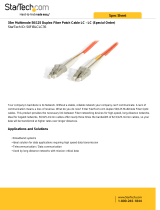
Optional 1000BASE-SX Module (VM2512A-1SX-SC-M)
Figure 1-6. Single-Port 1000BASE-SX Gigabit Module
Using multimode fiber optic cable, the 1000BASE-SX port can be connected to a
remote site up to 550 m (1805 ft) away. The 1000BASE-SX Gigabit module operates
at 1 Gbps, with support for full-duplex mode and flow control. This module is fitted
with an SC connector, but you can attach an ST plug to the switch using the SC-ST
Converter (Part Number: ST5002).
Note: If the attached device does not support auto-negotiation, you will have to manually
configure the other device to full duplex and no flow control.
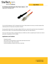
Optional 1000BASE-LX Module (VM2512A-1LX-SC-S)
Figure 1-7. Single-Port 1000BASE-LX Gigabit Module
Using single-mode fiber optic cable, the 1000BASE-LX port can be connected to a
remote site up to 5 km (16404 ft) away. The 1000BASE-LX Gigabit module operates
at 1 Gbps, with support for full-duplex mode and flow control. This module is fitted
with an SC connector, but you can attach an ST plug to the switch using the SC-ST
Converter (Part Number: ST5002).
Note: If the attached device does not support auto-negotiation, you will have to manually
configure the other device to full duplex and no flow control.
Optional 1000BASE-X GBIC Module (VM2512A-1GX-GBIC)
Figure 1-8. Single Port 1000BASE-X GBIC Module
RX
TX
VM2512A-1SX-SC-M
1000BASE-SX Multimode Module
RX
TX
VM2512A-1LX-SC-S
1000BASE-LX Singlemode Module
VM2512A-1GX-GBIC
1000BASE-X GBIC Module
/