CheetahSwitch Workgroup-3627
Installation Guide


Installation Guide
CheetahSwitch Workgroup-3627
Multilayer Workgroup Switch
with 24 10BASE-T / 100BASE-TX (RJ-45) Ports,
and 2 Slots for Optional 100BASE-FX or Gigabit Uplink Modules

Accton is a trademark of Accton Technology Corporation. Other trademarks or brand names mentioned
herein are trademarks or registered trademarks of their respective companies.
International Headquarters
No. 1 Creation Road III,
Science-based Industrial Park
Hsinchu 300, Taiwan, R.O.C.
Phone: +886-3-5770-270
Fax: +886-3-5770-267
Internet: [email protected]
Europe Headquarters
Edificio Conata II,
Calle Fructuós Gelabert 6-8, 2
o
, 4
a
,
08970 - Sant Joan Despí,
Barcelona, Spain.
Phone: +34-93-477-4920
Fax: +34-93-477-3774
Asia Pacific Headquarters
1 Claymore Drive
#08-05/06 Orchard Towers (Rear Block)
Singapore 229594
Phone: +65 238 6556
Fax: +65 238 6466
Internet: www.acctontech.com
USA Headquarters
6 Hughes
Irvine, CA 92618
Phone Numbers:
Sales: +800-926-9288
Support: +888-398-4101 or +949-707-4847
RMA: +800-762-4968
Fax: +949-707-2460
Copyright © 2001 by Accton Technology Corporation. All rights reserved.
No part of this document may be copied or reproduced in any form or by any means without the prior written
consent of Accton Technology Corporation.
Accton makes no warranties with respect to this documentation and disclaims any implied warranties of
merchantability, quality, or fitness for any particular purpose. The information in this document is subject to
change without notice. Accton reserves the right to make revisions to this publication without obligation to
notify any person or entity of any such changes.
ES3627
E122001-R03
150633-102

Warranty
Accton warrants to the original owner that the product delivered in this package will be
free from defects in material and workmanship for a period of three (3) years from the
date of purchase from Accton or its Authorized reseller. For the warranty to apply, you
must register your purchase by returning the registration card indicating the date of
purchase and including proof of purchase. There will be a minimal charge to replace
consumable components, such as fuses, power transformers, and mechanical cooling
devices. The warranty does not cover the product if it is damaged in the process of being
installed. Accton recommends that you have the company from whom you purchased this
product install it.
THE ABOVE WARRANTY IS IN LIEU OF ANY OTHER WARRANTY, WHETHER
EXPRESS, IMPLIED OR STATUTORY, INCLUDING BUT NOT LIMITED TO ANY
WARRANTY OF MERCHANTABILITY, FITNESS FOR A PARTICULAR PURPOSE, OR
ANY WARRANTY ARISING OUT OF ANY PROPOSAL, SPECIFICATION OR SAMPLE.
ACCTON SHALL NOT BE LIABLE FOR INCIDENTAL OR CONSEQUENTIAL
DAMAGES. ACCTON NEITHER ASSUMES NOR AUTHORIZES ANY PERSON TO
ASSUME FOR IT ANY OTHER LIABILITY.


i
Compliances
FCC - Class A
This equipment generates, uses, and can radiate radio frequency energy and, if not
installed and used in accordance with the instruction manual, may cause interference to
radio communications. It has been tested and found to comply with the limits for a Class A
computing device pursuant to Subpart B of Part 15 of FCC Rules, which are designed to
provide reasonable protection against such interference when operated in a commercial
environment. Operation of this equipment in a residential area is likely to cause
interference, in which case the user, at his own expense, will be required to take whatever
measures may be required to correct the interference. You are cautioned that changes or
modifications not expressly approved by the party responsible for compliance could void
your authority to operate the equipment.
You may use unshielded twisted-pair (UTP) for RJ-45 connections - Category 3 or greater
for 10 Mbps connections, and Category 5 for 100 Mbps connections. For fiber optic
connections, you may use 50/125 or 62.5/125 micron multimode fiber or 9/125 micron
single-mode fiber.
Warnings: 1
. Wear an anti-static wrist strap or take other suitable measures to prevent
electrostatic discharge when handling this equipment.
2. When connecting this hub to a power outlet, connect the field ground lead
on the tri-pole power plug to a valid earth ground line to prevent electrical
hazards.
Industry Canada - Class A
This digital apparatus does not exceed the Class A limits for radio noise emissions from
digital apparatus as set out in the interference-causing equipment standard entitled
“Digital Apparatus,” ICES-003 of the Department of Communications.
Cet appareil numérique respecte les limites de bruits radioélectriques applicables aux
appareils numériques de Classe A prescrites dans la norme sur le matériel brouilleur:
“Appareils Numériques,” NMB-003 édictée par le ministère des Communications.
Japan VCCI Class A

Compliances
ii
CE Mark Declaration of Conformance for EMI and Safety (EEC)
This information technology equipment complies with the requirements of the Council
Directive 89/336/EEC on the Approximation of the laws of the Member States relating to
Electromagnetic Compatibility and 73/23/EEC for electrical equipment used within certain
voltage limits and the Amendment Directive 93/68/EEC. For the evaluation of the
compliance with these Directives, the following standards were applied:
Warning! Do not plug a phone jack connector in the RJ-45 port. This may damage this
device. Les raccordeurs ne sont pas utilisé pour le système téléphonique!
Taiwan BSMI Class A
Australia AS/NZS 3548 (1995) - Class A
RFI Emission: • Limit class A according to EN 55022:1998
• Limit class A for harmonic current emission according to EN 61000-3-2/1995
• Limitation of voltage fluctuation and flicker in low-voltage supply system
according to EN 61000-3-3/1995
Immunity: • Product family standard according to EN 55024:1998
• Electrostatic Discharge according to EN 61000-4-2:1995
(Contact Discharge: ±4 kV, Air Discharge: ±8 kV)
• Radio-frequency electromagnetic field according to EN 61000-4-3:1996
(80 - 1000 MHz with 1 kHz AM 80% Modulation: 3 V/m)
• Electrical fast transient/burst according to EN 61000-4-4:1995 (AC/DC power
supply: ±1 kV, Data/Signal lines: ±0.5 kV)
• Surge immunity test according to EN 61000-4-5:1995
(AC/DC Line to Line: ±1 kV, AC/DC Line to Earth: ±2 kV)
• Immunity to conducted disturbances, Induced by radio-frequency fields:
EN 61000-4-6:1996 (0.15 - 80 MHz with 1 kHz AM 80% Modulation: 3 V/m)
• Power frequency magnetic field immunity test according to
EN 61000-4-8:1993
(1 A/m at frequency 50 Hz)
• Voltage dips, short interruptions and voltage variations immunity test
according to EN 61000-4-11:1994 (>95% Reduction @10 ms, 30%
Reduction @500 ms, >95% Reduction @5000 ms)
LVD: • EN 60950 (A1/1992; A2/1993; A3/1993; A4/1995; A11/1997)

Safety Compliance
iii
Safety Compliance
Warning: Fiber Optic Port Safety
Avertissment: Ports pour fibres optiques - sécurité sur le plan optique
Warnhinweis: Faseroptikanschlüsse - Optische Sicherheit
Underwriters Laboratories Compliance Statement
Important! Before making connections, make sure you have the correct cord set. Check
it (read the label on the cable) against the following:
The unit automatically matches the connected input voltage. Therefore, no additional
adjustments are necessary when connecting it to any input voltage within the range
marked on the rear panel.
When using a fiber optic port, never look at the transmit laser while it is
powered on. Also, never look directly at the fiber TX port and fiber cable
ends when they are powered on.
Ne regardez jamais le laser tant qu'il est sous tension. Ne regardez
jamais directement le port TX (Transmission) à fibres optiques et les
embouts de câbles à fibres optiques tant qu'ils sont sous tension.
Niemals ein Übertragungslaser betrachten, während dieses
eingeschaltet ist. Niemals direkt auf den Faser-TX-Anschluß
und auf die Faserkabelenden schauen, während diese
eingeschaltet sind.
Operating Voltage Cord Set Specifications
120 Volts UL Listed/CSA Certified Cord Set
Minimum 18 AWG
Type SVT or SJT three conductor cord
Maximum length of 15 feet
Parallel blade, grounding type attachment plug rated 15A, 125V
240 Volts (Europe only) Cord Set with H05VV-F cord having three conductors with
minimum diameter of 0.75 mm
2
IEC-320 receptacle
Male plug rated 10A, 250V
CLASS I
LASER DEVICE
DISPOSITIF LASER
DE CLASSE I
LASERGER
DER KLASSE I
ÄT

Compliances
iv
Wichtige Sicherheitshinweise (Germany)
1. Bitte lesen Sie diese Hinweise sorgfältig durch.
2. Heben Sie diese Anleitung für den späteren Gebrauch auf.
3. Vor jedem Reinigen ist das Gerät vom Stromnetz zu trennen. Verwenden Sie keine
Flüssigoder Aerosolreiniger. Am besten eignet sich ein angefeuchtetes Tuch zur
Reinigung.
4. Die Netzanschlu ßsteckdose soll nahe dem Gerät angebracht und leicht zugänglich sein.
5. Das Gerät ist vor Feuchtigkeit zu schützen.
6. Bei der Aufstellung des Gerätes ist auf sicheren Stand zu achten. Ein Kippen oder Fallen
könnte Beschädigungen hervorrufen.
7. Die Belüftungsöffnungen dienen der Luftzirkulation, die das Gerät vor Überhitzung schützt.
Sorgen Sie dafür, daß diese Öffnungen nicht abgedeckt werden.
8. Beachten Sie beim Anschluß an das Stromnetz die Anschlußwerte.
9. Verlegen Sie die Netzanschlußleitung so, daß niemand darüber fallen kann. Es sollte auch
nichts auf der Leitung abgestellt werden.
10. Alle Hinweise und Warnungen, die sich am Gerät befinden, sind zu beachten.
11. Wird das Gerät über einen längeren Zeitraum nicht benutzt, sollten Sie es vom Stromnetz
trennen. Somit wird im Falle einer Überspannung eine Beschädigung vermieden.
12. Durch die Lüftungsöffnungen dürfen niemals Gegenstände oder Flüssigkeiten in das Gerät
gelangen. Dies könnte einen Brand bzw. elektrischen Schlag auslösen.
13. Öffnen sie niemals das Gerät. Das Gerät darf aus Gründen der elektrischen Sicherheit nur
von authorisiertem Servicepersonal geöffnet werden.
14. Wenn folgende Situationen auftreten ist das Gerät vom Stromnetz zu trennen und von einer
qualifizierten Servicestelle zu überprüfen:
a. Netzkabel oder Netzstecker sind beschädigt.
b. Flüssigkeit ist in das Gerät eingedrungen.
c. Das Gerät war Feuchtigkeit ausgesetzt.
d. Wenn das Gerät nicht der Bedienungsanleitung entsprechend funktioniert oder Sie mit
Hilfe dieser Anleitung keine Verbesserung erzielen.
e. Das Gerät ist gefallen und/oder das Gehäuse ist beschädigt.
f. Wenn das Gerät deutliche Anzeichen eines Defektes aufweist.
15. Zum Netzanschluß dieses Gerätes ist eine geprüfte Leitung zu verwenden. Für einen
Nennstrom bis 6A und einem Gerätegewicht größer 3kg ist eine Leitung nicht leichter als
H05VV-F, 3G, 0.75mm
2
einzusetzen.
Der arbeitsplatzbezogene Schalldruckpegel nach DIN 45 635 Teil 1000 beträgt 70dB(A) oder
weniger.

v
Contents
Chapter 1: About the CheetahSwitch Workgroup-3627 1-1
Overview 1-1
Switch Architecture 1-1
Management Options 1-2
Description of Hardware 1-4
10BASE-T/100BASE-TX Ports 1-4
Status LEDs 1-4
Optional Media Extender Modules 1-5
Optional Redundant Power Unit 1-7
Power Supply Receptacles 1-7
Features and Benefits 1-8
Connectivity 1-8
Expandability 1-8
Performance 1-8
Management 1-9
Chapter 2: Network Planning 2-1
Introduction to Switching 2-1
Sample Applications 2-2
Collapsed Backbone 2-2
Central Wiring Closet 2-3
Remote Connections with Fiber Cable 2-4
Making VLAN Connections 2-5
Using Layer 3 Routing 2-6
Connectivity Rules 2-7
1000 Mbps Gigabit Ethernet Collision Domain 2-7
100 Mbps Fast Ethernet Collision Domain 2-7
10 Mbps Ethernet Collision Domain 2-8
Application Notes 2-9
Chapter 3: Installing the Switch 3-1
Selecting a Site 3-1
Equipment Checklist 3-1
Package Contents 3-1
Optional Rack-Mounting Equipment 3-2
Mounting 3-2
Rack Mounting 3-2
Desktop or Shelf Mounting 3-3
Installing an Optional Module into the Switch 3-4
Connecting to a Power Source 3-5

Contents
vi
Chapter 4: Making Network Connections 4-1
Connecting Network Devices 4-1
Twisted-Pair Devices 4-1
Cabling Guidelines 4-1
Connecting to PCs, Servers, Hubs and Switches 4-1
Wiring Closet Connections 4-2
Fiber Optic Devices 4-3
Appendix A: Troubleshooting A-1
Diagnosing Switch Indicators A-1
Power and Cooling Problems A-1
Installation A-1
In-Band Access A-1
Appendix B: Cables B-1
Specifications B-1
Twisted-Pair Cable and Pin Assignments B-1
10BASE-T/100BASE-TX Pin Assignments B-2
Straight-Through Wiring B-2
Crossover Wiring B-3
1000BASE-T Pin Assignments B-3
1000BASE-T Cable Requirements B-4
Cable Testing for Existing Category 5 Cable B-4
Adjusting Existing Category 5 Cabling to Run 1000BASE-T B-4
Console Port Pin Assignments B-5
DB-9 Port Pin Assignments B-5
Console Port to 9-Pin DTE Port on PC B-5
Console to 25-Pin DTE Port on PC B-5
Appendix C: Specifications C-1
Physical Characteristics C-1
Switch Features C-2
Management Features C-3
Standards C-3
Compliances C-3
Warranty C-4
Slide-in Modules C-4
1000BASE-SX Extender Module C-4
1000BASE-LX Extender Module C-4
1000BASE-T Extender Module C-5
100BASE-FX Extender Module C-5
Appendix D: Ordering Information D-1
Glossary
Index

1-1
Chapter 1: About the CheetahSwitch Workgroup-3627
Overview
Accton’s CheetahSwitch Workgroup-3627 is an intelligent multilayer (Layer 2 and 3)
switch with 24 10BASE-T/100BASE-TX ports plus two slots on the rear panel for
slide-in 1000BASE-LX, 1000BASE-SX, 1000BASE-T or 100BASE-FX modules.
This switch can easily tame your network with full support for Spanning Tree
Protocol, Multicast Switching, Virtual LANs, and IP routing. It brings order to poorly
performing networks by segregating them into separate broadcast domains with
IEEE 802.3Q compliant VLANs, empowers multimedia applications with multicast
switching and QoS services, and eliminates conventional router bottlenecks.
It can be used to augment or completely replace slow legacy routers,
off-loading local
IP traffic to release valuable resources for non-IP routing or WAN access. With
wire-speed performance for both Layer 2 switching and Layer 3 routing, this switch
can significantly improve the throughput between IP segments or VLANs.
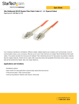
Figure 1-1. Front and Rear Panels
Switch Architecture
The CheetahSwitch employs a wire-speed, non-blocking switching fabric. This
permits simultaneous wire-speed transport of multiple packets at low latency on all
ports. This switch also features full-duplex capability on all ports, which effectively
doubles the bandwidth of each connection.
Switching Method
For communications between different VLANs, this switch uses IP routing with RIP,
RIPv2, or DVMRP protocol. For communications within the same VLAN, the switch
uses store-and-forward switching to ensure maximum data integrity. In
store-and-forward switching mode, the entire packet must be received into a buffer
and checked for validity before being forwarded. This prevents errors from being
propagated throughout the network.
1
2
3
4
5
6
7
8
9
10
11
12
13
14
15
16
17
18
19
20
21
22
23
24
S
t
a
t
u
s
L
i
n
k
L
i
n
k
S
t
a
t
u
s
S
t
a
t
u
s
1
3
1
1
4
1
5
1
6
1
7
1
8
1
9
2
0
2
1
2
2
2
3
2
4
M
2
M
1
F
D
X
A
C
T
C
O
L
1
0
0
M
P
o
w
e
r
R
P
U
S
N
M
P
C
o
n
s
o
l
e
23456 7891
0
11 1
2
CheetahSwitch Workgroup-3627
ES3627
o
Media Slots
1000BASE-LX, 1000BASE-SX,
1000BASE-T or 100BASE-FX modules
System Indicators
Power, Redundant Power, SNMP, Console
100-240 V
50-60 Hz 3 A
10/100 Mbps RJ-45 Ports
Mode Selection
Display selection includes:
Collision, activity,
duplex mode, speed
Port Status Indicators
Link - On: link/enable; Off: no link;
Status - Depends on mode selection
Redundant Power
Socket
Power Socket
Console Port
Use this port for console
or modem connection
V
A
3.3
30
5
6
12
0.7
DC Input

About the CheetahSwitch Workgroup-3627
1-2
Management Options
This switch contains a comprehensive array of LEDs for “at-a- glance” monitoring of
network and port status. It also includes a built-in network management agent that
allows the switch to be managed in-band using SNMP or RMON (Groups 1, 2, 3 and
9) protocols, with a Web browser, or remotely via Telnet. The switch provides an
RS-232 serial port (DB-9 connector) on the rear panel for out-of-band management.
A PC may be connected to this port
for configuration and monitoring out-of-band via a
full-handshaking
null-modem cable. (See Appendix B for wiring options.)
This switch provides a wide range of advanced performance- enhancing features.
Port-based and tagged VLANs, plus support for automatic GVRP VLAN registration
and GMRP multicast group registration provide traffic security and efficient use of
network bandwidth. QoS priority queueing ensures the minimum delay for moving
real-time multimedia data across the network. Flow control eliminates the loss of
packets due to bottlenecks caused by port saturation. Broadcast storm control
prevents broadcast traffic storms from engulfing the network. Layer 3 routing can be
used to connect segregated subnets and VLANs. Some of this switch’s advanced
features are described below. For a detailed description, refer to the Management
Guide.
Spanning Tree Protocol
The CheetahSwitch supports IEEE 802.1D Spanning Tree Protocol. This protocol
adds a level of fault tolerance by allowing two or more redundant connections to be
created between a pair of LAN segments. When there are multiple physical paths
between segments, the protocol will choose a single path and disable all others to
ensure that only one route exists between any two stations on the network. This
prevents the creation of network loops. However, if the chosen path should fail for
any reason, an alternate path will be activated to maintain the connection.
The default setting for the Spanning Tree Protocol is “enabled.” This protocol may be
configured out-of-band via the serial console port, or in-band via the Web interface,
Telnet, or SNMP network management software.
VLANs
The CheetahSwitch supports up to 256 VLANs. A Virtual LAN is a collection of
network nodes that share the same collision domain regardless of their physical
location or connection point in the network. By segmenting your network into
VLANs, you can:
• Eliminate broadcast storms which severely degrade performance in a flat network.
• Simplify network management for node changes/moves by remotely configuring
VLAN membership for any port, rather than having to manually change the node’s
IP address.
• Provide data security by restricting all traffic to the originating VLAN, except where
a connection is explicitly defined via the switch’s routing service.

Overview
1-3
Multicast Switching
Specific multicast traffic can be assigned to its own VLAN to ensure that it does not
interfere with normal network traffic and to guarantee real-time delivery by setting
the required priority level for the designated VLAN. The switch uses IGMP Snooping
and GMRP at Layer 2, and IGMP at Layer 3 to manage multicast group registration.
Traffic Priority
This switch provides Quality of Service (QoS) by prioritizing each packet based on
the required level of service, using two distinct categories with Weighted Fair
Queuing. It uses IEEE 802.1p and 802.1Q tags to prioritize incoming traffic based on
input from the end-station application. These functions can be used to provide
independent priorities for delay-sensitive data and best-effort data.
Layer 3 Routing
The CheetahSwitch provides Layer 3 IP routing. To maintain a high rate of
throughput, the switch forwards all intra-segment traffic, and routes only traffic that
passes outside the segment. By providing wire-speed routing, you can easily link
your network segments or VLANs together without having to deal with the
bottlenecks or configuration hassles normally associated with conventional routers.
Most traffic can be routed based on information maintained within the switch’s own
database. If the address is not in the switching database, the switch will use RIP or
RIPv2 protocol to request the address. If the address still cannot be found, the
switch can pass the packet to a default router for handling.
The switch uses DVMRP protocol to determine the routing for multicast packets. If
no hosts have subscribed to the indicated multicast service, the packet will be
dropped.

About the CheetahSwitch Workgroup-3627
1-4
Description of Hardware
10BASE-T/100BASE-TX Ports
These are dual-speed RJ-45 ports. Because all ports on this switch support
automatic MDI/MDI-X operation, you can use straight-through cables for all network
connections to PCs or servers, or to other switches or hubs. (See “10BASE-T/
100BASE-TX Pin Assignments” on page B-2.)
Each of these ports support IEEE 802.3x auto-negotiation, so the optimum
transmission mode (half or full duplex), and data rate (10 or 100 Mbps) can be
selected automatically. If a device connected to one of these ports does not support
auto-negotiation, the communication mode of that port can be configured manually.
Each port also supports auto-negotiation of flow control, so the switch can
automatically prevent port buffers from becoming saturated.
Status LEDs
The LEDs, which are located on the front panel for easy viewing, are shown below
and described in the following table.
Figure 1-2. Port and System LEDs
Port Status LEDs
LED Condition Status
RJ-45 Ports
Link On Port has a valid connection, port enabled
Flashing Port has a valid connection, port disabled
Status
*
Displays state for selected status mode
COL
*
Flashing Indicates collision on half-duplex links
ACT
*
On Shows that traffic is crossing the port
FDX
*
On Port is operating at full duplex
Off Port is operating at half duplex
100M
*
On Port is operating at 100 Mbps
Off Port is operating at 10 Mbps
Status
Link
Link
Status
Status
13
1
14 15 16 17 18 19 20 21 22 23 24 M2
M
1
FDX
ACT
COL
100M
Power
RPU
SNMP
Console
23456789101112

Description of Hardware
1-5
Optional Media Extender Modules
Optional 1000BASE-SX Module (EM4501C-SX-SC)
Figure 1-3. Single-Port 1000BASE-SX Gigabit Module
Using multimode fiber optic cable, the 1000BASE-SX port can be connected to a
remote site up to 550 m (1805 ft) away. The 1000BASE-SX Gigabit module operates
at 1 Gbps, with support for full-duplex mode and flow control. This module is fitted
with an SC connector, but you can attach an ST plug to the switch using the SC-ST
Converter (Part Number: ST5002).
Module Ports
Status
On A module is installed in this port
Link On Port has a valid connection, port enabled
Flashing Port has a valid connection, port disabled
* Use the Status button to select LED display mode.
System Status LEDs
LED Condition Status
Power On Switch is receiving power
RPU On Redundant power unit is receiving power
SNMP Flashing Switch has processed an SNMP command
Console On One or more management connections established
(console or Telnet)
Port Status LEDs
LED Condition Status
EM4501C-SX-SC
1000BASE SX-SC Expansion Module
RX
TX

About the CheetahSwitch Workgroup-3627
1-6
Optional 1000BASE-LX Module (EM4501C-LX-SC)
Figure 1-4. Single-Port 1000BASE-LX Gigabit Module
Using single-mode fiber optic cable, the 1000BASE-LX port can be connected to a
remote site up to 5 km (16404 ft) away. The 1000BASE-LX Gigabit module operates
at 1 Gbps, with support for full-duplex mode and flow control.
Optional 1000BASE-T Module (EM4501C-T)
Figure 1-5. Single-Port 1000BASE-T Gigabit Module
Using Category 5 or 5e twisted-pair cable you can connect to another device up to
100 m (328 ft) away. The 1000BASE-T module operates at 1 Gbps, full duplex, and
supports auto-negotiation of flow control. Note that you should first test the cable
installation for IEEE 802.3ab compliance. See “1000BASE-T Cable Requirements”
on page B-3.
Optional 100BASE-FX Module (EM3526JA-1FX-SC-S)
Figure 1-6. Single-Port 100BASE-FX Single-Mode Module
Using single-mode fiber optic cable, the 100BASE-FX port can be connected to a
remote site up to 20 km (12.43 miles) away. The 100BASE-FX module operates at
100 Mbps, with support for full-duplex mode and flow control.
EM4501C-LX-SC
1000BASE LX-SC Expansion Module
RX
TX
1000BASE-T Expansion Module
EM4501C-T
100BASE-FX Single-Mode Module
EM3526JA-1FX-SC-S
TX
RX

Description of Hardware
1-7
Optional 100BASE-FX Module (EM3526JA-1FX-SC-M)
Figure 1-7. Single-Port 100BASE-FX Multimode Module
Using multimode fiber optic cable, the 100BASE-FX port can be connected to a
remote site up to 2 km (1.24 miles) away. The 100BASE-FX module operates at 100
Mbps, with support for full-duplex mode and flow control. This module is fitted with
an SC connector, but you can attach an ST plug to the switch using the SC-ST
Converter (Part Number: ST5002).
Optional Redundant Power Unit
Accton provides an optional Redundant Power Unit (RPU), RPU60W, that can
supply power to the switch in the event of failure of the internal power supply.
Power Supply Receptacles
There are two power receptacles on the rear panel of the switch. The standard
power receptacle is for the AC power cord. The receptacle labeled “DC Input” is for
the optional Redundant Power Unit (RPU).
Figure 1-8. Power Supply Receptacles
100BASE-FX Multimode Module
EM3526JA-1FX-SC-M
TX
RX
100-240 V
50-60 Hz 2 A
V
A
3.3
30
5
6
12
0.7
DC Input

About the CheetahSwitch Workgroup-3627
1-8
Features and Benefits
Connectivity
• 24 dual-speed ports for easy Fast Ethernet integration and for protection of your
investment in legacy LAN equipment
• Auto-negotiation enables each RJ-45 port to automatically select the optimum
communication mode (half or full duplex) if this feature is supported by the attached
device; otherwise the port can be configured manually
• Independent RJ-45 10BASE-T/100BASE-TX ports with support for auto MDI/
MDI-X
• Unshielded (UTP) cable supported on all RJ-45 ports: Category 3, 4 or 5 for 10
Mbps connections and Category 5 for 100 Mbps connections
• IEEE 802.3 Ethernet, 802.3u Fast Ethernet, 802.3z and 802.3ab Gigabit Ethernet
compliance ensures compatibility with standards-based hubs, network cards and
switches from any vendor
Expandability
• Optional single-port 1000BASE-SX Gigabit module that can run up to 550 meters
(using 50/125 micron multimode fiber cable), and operates at 1 Gbps, full duplex,
with auto-negotiation for flow control.
• Optional single-port 1000BASE-LX Gigabit module that can run up to 5 km (using
9/125 micron single-mode fiber cable), and operates at 1 Gbps, full duplex, with
auto-negotiation for flow control.
• Optional single-port 1000BASE-T Gigabit module that can run up to 100 meters
(using 100-ohm Category 5 or 5e unshielded twisted-pair (UTP) or shielded
twisted-pair (STP) cable), and operates at 1 Gbps, full duplex, with auto negotiation
for flow control.
• Optional single-port 100BASE-FX modules that can run up to 2 km (using 62.5/125
or 50/125 micron, multimode fiber cable), or 20 km (using 9/125 micron
single-mode fiber cable) and operate at 100 Mbps, full duplex, with
auto-negotiation for flow control.
Performance
• Transparent bridging
• Aggregate bandwidth of up to 8.8 Gbps
• Switching Table with a total of 12K entries
• Provides Store-and-Forward switching for intra-VLAN traffic, and IP routing for
inter-VLAN traffic
• Supports wire-speed switching at Layer 2, and wire-speed routing at Layer 3
• Supports flow control, using back pressure for half duplex and IEEE 802.3x for full
duplex
• Broadcast Storm Control
• Includes support for an optional Redundant Power Unit
• Desktop or rack-mountable
Page is loading ...
Page is loading ...
Page is loading ...
Page is loading ...
Page is loading ...
Page is loading ...
Page is loading ...
Page is loading ...
Page is loading ...
Page is loading ...
Page is loading ...
Page is loading ...
Page is loading ...
Page is loading ...
Page is loading ...
Page is loading ...
Page is loading ...
Page is loading ...
Page is loading ...
Page is loading ...
Page is loading ...
Page is loading ...
Page is loading ...
Page is loading ...
Page is loading ...
Page is loading ...
Page is loading ...
Page is loading ...
Page is loading ...
Page is loading ...
Page is loading ...
Page is loading ...
Page is loading ...
Page is loading ...
Page is loading ...
Page is loading ...
Page is loading ...
Page is loading ...
Page is loading ...
Page is loading ...
Page is loading ...
Page is loading ...
Page is loading ...
Page is loading ...
Page is loading ...
Page is loading ...
Page is loading ...
Page is loading ...
/