Accton Technology Edge-corE EC3802-WDM User manual

Type
User manual

This manual is also suitable for

Powered by Accton
www.edge-core.com
Installation Guide
EC3802-WDM
Media Converter
Installation Guide
FTTH Media Converter - EC3802-WDM
with One Fixed 100BASE-BX Single-Fiber Line Connection,
and One 10BASE-T / 100BASE-TX (RJ-45) Port
EC3802-WDM
E012008/ST-R01
150200065000A
v
Compliances and Safety Warnings
FCC - Class B
This equipment has been tested and found to comply with the limits for a Class B
digital device, pursuant to Part 15 of the FCC Rules. These limits are designed to
provide reasonable protection against harmful interference in a residential
installation. This equipment generates, uses and can radiate radio frequency energy
and, if not installed and used in accordance with instructions, may cause harmful
interference to radio communications. However, there is no guarantee that the
interference will not occur in a particular installation. If this equipment does cause
harmful interference to radio or television reception, which can be determined by
turning the equipment off and on, the user is encouraged to try to correct the
interference by one or more of the following measures:
Reorient the receiving antenna
Increase the separation between the equipment and receiver
Connect the equipment into an outlet on a circuit different from that to which the
receiver is connected
Consult the dealer or an experienced radio/TV technician for help
You are cautioned that changes or modifications not expressly approved by the
party responsible for compliance could void your authority to operate the equipment.
You may use unshielded twisted-pair (UTP) for RJ-45 connections - Category 3 or
better for 10 Mbps connections, or Category 5 or better for 100 Mbps connections.
For fiber optic connections, you may use 9/125 micron single-mode fiber.
vi
CE Mark Declaration of Conformance for EMI and Safety (EEC)
This information technology equipment complies with the requirements of the Council
Directive 89/336/EEC on the Approximation of the laws of the Member States relating to
Electromagnetic Compatibility and 73/23/EEC for electrical equipment used within certain
voltage limits and the Amendment Directive 93/68/EEC. For the evaluation of the
compliance with these Directives, the following standards were applied:
Caution: Do not plug a phone jack connector in the RJ-45 port. This may damage this
device.
Attention: Les raccordeurs ne sont pas utilisés pour le système téléphonique!
RFI Emission: Limit class B according to EN 55022:1997
Limit class B for harmonic current emission according to EN 61000-3-2/1995
Limitation of voltage fluctuation and flicker in low-voltage supply system
according to EN 61000-3-3/1995
Immunity: Product family standard according to EN 55024:1998
Electrostatic Discharge according to EN 61000-4-2:1995
(Contact Discharge: ±4 kV, Air Discharge: ±8 kV)
Radio-frequency electromagnetic field according to EN 61000-4-3:1996
(80 - 1000 MHz with 1 kHz AM 80% Modulation: 3 V/m)
Electrical fast transient/burst according to EN 61000-4-4:1995 (AC/DC power
supply: ±1 kV, Data/Signal lines: ±0.5 kV)
Surge immunity test according to EN 61000-4-5:1995
(AC/DC Line to Line: ±1 kV, AC/DC Line to Earth: ±2 kV)
Immunity to conducted disturbances, Induced by radio-frequency fields:
EN 61000-4-6:1996 (0.15 - 80 MHz with 1 kHz AM 80% Modulation: 3 V/m)
Power frequency magnetic field immunity test according to
EN 61000-4-8:1993
(1 A/m at frequency 50 Hz)
Voltage dips, short interruptions and voltage variations immunity test
according to EN 61000-4-11:1994 (>95% Reduction @10 ms, 30%
Reduction @500 ms, >95% Reduction @5000 ms)
LVD: EN 60950-1 :2001
vii
Safety Compliance
Warning: Fiber Optic Port Safety
Avertissment: Ports pour fibres optiques - sécurité sur le plan optique
Warnhinweis: Faseroptikanschlüsse - Optische Sicherheit
Environmental Statement
The manufacturer of this product endeavors to sustain an environmentally-friendly policy
throughout the entire production process. This is achieved though the following means:
Adherence to national legislation and regulations on environmental production
standards.
Conservation of operational resources.
Waste reduction and safe disposal of all harmful un-recyclable by-products.
Recycling of all reusable waste content.
Design of products to maximize recyclables at the end of the product’s life span.
Continual monitoring of safety standards.
End of Product Life Span
This product is manufactured in such a way as to allow for the recovery and disposal of all
included electrical components once the product has reached the end of its life.
Manufacturing Materials
There are no hazardous nor ozone-depleting materials in this product.
Documentation
All printed documentation for this product uses biodegradable paper that originates from
sustained and managed forests. The inks used in the printing process are non-toxic.
When using a fiber optic port, never look at the transmit laser while it is
powered on. Also, never look directly at the fiber TX port and fiber cable
ends when they are powered on.
Ne regardez jamais le laser tant qu'il est sous tension. Ne regardez
jamais directement le port TX (Transmission) à fibres optiques et les
embouts de câbles à fibres optiques tant qu'ils sont sous tension.
Niemals ein Übertragungslaser betrachten, während dieses
eingeschaltet ist. Niemals direkt auf den Faser-TX-Anschluß
und auf die Faserkabelenden schauen, während diese
eingeschaltet sind.
DISPOSITIF LASER
DE CLASSE I
LASERGER
DER KLASSE I
ÄT
viii
About This Guide
Purpose
This guide details the hardware features of this device, including the physical and
performance-related characteristics, and how to install it.
Audience
The guide is intended for use by network administrators who are responsible for installing
and setting up network equipment; consequently, it assumes a basic working knowledge
of LANs (Local Area Networks).
Conventions
The following conventions are used throughout this guide to show information:
Note: Emphasizes important information or calls your attention to related features or
instructions.
Caution: Alerts you to a potential hazard that could cause loss of data, or damage the
system or equipment.
Warning:Alerts you to a potential hazard that could cause personal injury.
Revision History
This section summarizes the changes in each revision of this guide.
November 2007 Revision
This is the first revision of this guide.
ix
Contents
Introduction 11
Key Features 12
Description of Hardware 13
Fiber Cable Connection 13
UTP Port 14
Power Connector 14
External DIP Switch Settings 15
LED Indicators 16
Installing the FTTH CPE 17
Package Contents 17
System Requirements 17
Mounting the CPE 18
Desktop Mounting 19
Wall Mounting 19
Connecting to the CPE 20
Making a Connection to the UTP Port 20
Powering On the CPE 21
Configuring the TCP/IP Protocol 21
Windows 95/98/NT 21
Windows 2000 21
Windows XP 22
Mac OS Systems 22
Product Specifications 23
Troubleshooting 24
Diagnosing CPE Indicators 24
If You Cannot Connect to the Internet 24
Upgrading Firmware 25
Port and Cable Assignments 26
RJ-45 Ethernet Port 26
Straight-Through Wiring 27
Crossover Wiring 27
x
Contents
11
Introduction
Fiber-To-The-Home (FTTH) has always been an attractive option for Internet
access. It has all the benefits of optical fiber. It provides a future-proof network, in
that you do not have to go through the hassles of upgrading from ADSL to xDSL, or
digital co-ax to digital wireless. It does not have to struggle with electromagnetic
interference problems, and with no active “outside-plant” components, it offers the
highest reliability. Moreover, it does not require electric power and is immune to
lightning and other transients. These properties of fiber lead to the lowest possible
power and operational costs, such as maintenance, provisioning and facilities
planning.
The EC3802-WDM Media Converter is an ideal Customer Premises Equipment
(CPE) for an FTTH system. This CPE is a single-channel fiber-to-copper media
converter housed in a compact unit. It allows a service provider to extend an
Ethernet connection over optical fiber directly to a subscriber. The CPE has an
embedded (no external plug/socket) ITU-T G.985 full-duplex single-fiber
single-mode cable connection that runs from the service provider’s central office
(CO). The single-mode fiber connection can be run up to distances of 15 km from
the CO. The CPE also provides one standard 10/100BASE-TX RJ-45 Ethernet port
for connecting to a customer’s PC, switch, or other network device using twisted-pair
cable.
EC3802-WDM CPE
100BASE-FX full-duplex
single-fiber (WDM) link to CO
(up to 15 km)
Subscriber’s Home
Central Office
(CO)
10/100BASE-TX UTP
connection to computer
(up to 100 m)
Introduction
12
Key Features
High-speed Internet access
Optical fiber port supports transmission distances up to 15 km (9.32 miles)
Built-in transparent bridging between different media segments
Supports 1K MAC addresses
forwards packets only if necessary
Always-on fast optical fiber connection eliminates dial-up delays, providing
transparent Internet access
Auto-negotiating 10/100BASE-TX Ethernet port
Provides DIP switch setting to force 10/100BASE-TX port speed, duplex mode,
and link loss forwarding (link down notification to peer)
Automatic MDI/X pinout selection on the Ethernet port
Compliant to IEEE 10BASE-T, 100BASE-TX, and 100BASE-BX standards
Provides back pressure for half-duplex and IEEE 802.3x flow control for full-duplex
Power can be supplied via PoE through the LAN port or through the AC adapter
Meets ITU-T G.985 physical layer specifications and OAM (including remote failure
indication, link monitor, loopback testing, and remote management)
Internal mechanism prevents fiber connection from being disconnected accidently
Natural air cooling system without using a fan
LEDs indicate link activity, speed, duplex mode, and PoE status
Simple plug-and-play installation
Space-saving compact size
Description of Hardware
13
Description of Hardware
The EC3802-WDM is an FTTH CPE product for high-speed Internet access
applications. This CPE includes an embedded fiber cable connection, an RJ-45
Ethernet LAN port, PoE on the LAN port, a DIP-switch for LAN port settings, LED
status indicators, and an AC power adapter connection.
The following figure shows the components of the CPE.
Fiber Cable Connection
The single-mode fiber cable connection from the service provider’s CO is embedded
(connected internally) within the CPE. There is no external plug and socket
connection, which prevents the CPE from being disconnected accidently. Also, there
are no configuration settings or maintenance necessary for the fiber cable link.
The single-fiber connection supports a 100BASE-BX full-duplex link to the CO. The
CPE’s fiber transceiver uses Wavelength Division Multiplexing (WDM) technology to
achieve bi-directional operation (1550 nm transmit, 1310 nm receive) over a single
optical fiber. The WDM single-mode fiber link can run up to 15 km (9.32 miles) from
the CO.
Vent (Natural Air
Cooling System)
Top Panel
LED Indicators
Rear Panel
DIP-Switch
(4 bit)
DC12V Line
(embedded)
RJ-45 socket
Fiber Line
(embedded)
Description of Hardware
14
UTP Port
The RJ-45 Ethernet port labeled “UTP” operates at 10 or 100 Mbps, and supports
auto-negotiation of speed, duplex mode (i.e., half or full duplex), flow control, and
MDI/X pinout selection. Automatic configuration of MDI or MDI-X pinout operation,
allows you to use straight-through cable for all connections. Where necessary, the
UTP port can also be forced to a specific speed and duplex mode via a DIP-switch
setting.
Note: The CPE may also receive Power over Ethernet (PoE) from a switch or other
network device that supplies power over the network cable based on the IEEE
802.3af standard. If the CPE is connected to a PoE source device through the LAN
port and also connected to a local power source through the AC power adapter,
PoE power will be used and input from the AC power adapter disabled.
Power Connector
The CPE does is powered on when the power adapter is connected to a power
source. The power adapter automatically adjusts to any voltage between 90~240
volts at 50 or 60 Hz. No voltage range settings are required.
Note: The CPE may also receive Power over Ethernet (PoE) from a switch or other
network device that supplies power over the network cable based on the IEEE
802.3af standard. If the CPE is connected to a PoE source device through the LAN
port and also connected to a local power source through the AC power adapter,
PoE power will be used and input from the AC power adapter disabled.
Description of Hardware
15
External DIP Switch Settings
The CPE has a four-bit DIP switch located on its rear panel next to the UTP port
(see figure below). The DIP switch allows you to enable/disable auto-negotiation for
the UTP port and manually force the speed and duplex mode setting. Also, there is
one switch for enabling link down notification for the fiber connection. Note that the
ON position for the DIP switch is down.
The following table lists the DIP-switch settings:
Note: Auto-negotiation must be disabled, i.e., switch Auto (bit 1) set to OFF, for switches
100 (bit 2) and Full (bit 3) to be functional.
DIP SW Bit Name Description
1 Auto ON: Auto-negotiation enabled.
OFF: Auto-negotiation disabled. (Forces setting using bits 2-3.)
2 100 ON: Port operating as 100BASE-TX. (Only applies if Auto is OFF.)
OFF: Port operating as 10BASE-T.
3 Full ON: Full-duplex mode. (Only applies if Auto is OFF.)
OFF: Half-duplex mode.
4 LLF ON: Enables link down notification on fiber link to peer.
OFF: Disables link down notification on fiber link to peer.
DIP Switch
DIP Switch On Position
Description of Hardware
16
LED Indicators
The CPE includes seven LED status indicators on the top panel. The LEDs are
detailed in the following figure and table.
LED Description
PWR ON: Power is on.
OFF: Power is off.
OPT ON: Fiber link is up.
OFF: Fiber link down.
TEST ON: Loopback test in progress.
OFF: No loopback test (normal mode).
PoE ON: PoE is enabled on the LAN port.
OFF: PoE is disabled on the LAN port.
Link ON: UTP port link is up.
Flashing: UTP port is transmitting or receiving data.
OFF: UTP port link is down.
100M ON: UTP port is operating at 100 Mbps.
OFF: UTP port is operating at 10 Mbps.
FULL ON: UTP port is operating in full-duplex mode.
OFF: UTP port is operating in half-duplex mode.
Installing the FTTH CPE
17
Installing the FTTH CPE
Before installing the CPE, verify that you have all the items listed under “Package
Contents.” If any of the items are missing or damaged, contact your service provider.
Also, be sure you have all the necessary tools and cabling before installing the CPE.
Package Contents
The package includes the following items:
One EC3802-WDM FTTH media converter (CPE), with AC power adapter
Four rubber foot pads
This Installation Guide
Please inform your service provider if there are any incorrect, missing or damaged
parts. If possible, retain the carton, including the original packing materials. Use
them again to repack the product in case there is a need to return it for repair.
System Requirements
The CPE requires the following computer features to operate:
A PC or Macintosh with a 10/100 Mbps Ethernet adapter card installed
For Internet access, the computer must be configured for TCP/IP
Installing the FTTH CPE
18
Mounting the CPE
Caution: The EC3802-WDM CPE is for indoor mounting only. Do not mount the unit on
the outside of a building.
The CPE includes rubber feet for desktop mounting.
Before you start installing the CPE, make sure you can provide the right operating
environment. Verify the following installation requirements:
Power requirements: 12 VDC via the attached AC power adapter. Make sure that
a properly grounded power outlet is within 1.8 m (6 ft) of the CPE.
The CPE should be located in a cool dry place, with at least 5 cm (2 in.) of space
on all sides for proper air flow.
Place the CPE out of direct sunlight, and away from heat sources or areas with a
high amount of electromagnetic interference. The temperature and humidity should
be within the ranges listed in the specifications.
Make sure the fiber line is carefully routed to the CPE in a way that does not incur
a bending radius in the cable of less than 30 mm.
Be sure that the CPE is accessible for the UTP Ethernet connection.
Make sure UTP cable is routed away from power lines, fluorescent lighting fixtures
and other sources of electrical interference such as radios, transmitters, etc.
The status LEDs are clearly visible.
Wall mounting using the
wall-mounting slots
Desktop Mounting
Horizontal mounting using
rubber feet
Wall Mounting
Installing the FTTH CPE
19
Desktop Mounting
The CPE can be mounted horizontally on any flat surface, such as a desktop or
shelf.
For horizontal mounting, simply stick the self-adhesive rubber foot pads (that come
with this package) on each of the four concave spaces located on the bottom of the
CPE. Then, place the CPE on the flat surface where it is to be installed.
Wall Mounting
The CPE can also be mounted on a wall. Two mounting slots are provided on the
bottom of the unit for this purpose. Be sure to position the CPE so that the front
panel LEDs can be viewed when the unit is operating.
Note: Wall mounting screws and wall plugs are not provided in the CPE package.
To mount the CPE on a plastered brick or concrete wall, follow these steps:
1. Mark the position of the mounting screws on the wall so they line up with the two
mounting slots on the bottom of the CPE.
2. Drill two holes of appropriate size for the wall plugs and screws (recommended
size T3 x 15L). Press the plugs firmly into the drilled holes until they are flush
with the surface of the wall.
3. Insert the screws into the wall plugs leaving about 3 mm (0.12 in.) clearance
from the wall.
4. Position the CPE over the mounting screws, then slide it down onto the screws.
To mount the CPE on a wood wall, follow these steps:
1. Mark the position of the mounting screws on the wall so they line up with the two
mounting slots on the bottom of the CPE.
2. Insert the screws into the wall leaving about 3 mm (0.12 in.) clearance from the
wall.
3. Position the CPE over the mounting screws, then slide it down onto the screws.
Rubber feet
Bottom surface
Installing the FTTH CPE
20
Connecting to the CPE
Caution: The CPE fiber line should be connected to the unit by a qualified technician
only. Do not attempt to remove the fiber cable from the CPE. If there are any
problems with the fiber cable connection, contact your service provider.
You can connect any computer with an Ethernet network interface card, a LAN
switch, hub, or other network device to the CPE’s UTP port.
Making a Connection to the UTP Port
The UTP port on the CPE supports automatic MDI and MDI-X pinout selection. This
allows you to use standard straight-through twisted-pair cables to connect to any
other network device (computers, switches, routers, or hubs).
See “Port and Cable Assignments” on page 26 for more information on connecting
straight-through or crossover UTP cables to MDI or MDI-X ports.
Caution: Do not plug a phone jack connector into any RJ-45 port. This may damage the
CPE. Instead, use only twisted-pair cable with RJ-45 connectors that conform
with FCC standards.
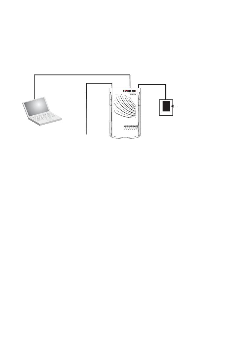
To connect the CPE’s UTP port directly to a computer, carry out the following steps:
1. Prepare the computer you wish to connect. Make sure you have installed a
10BASE-T or 100BASE-TX network interface card for connecting to the CPE’s
UTP port.
2. Check that the CPE’s UTP port has auto-negotiation enabled by setting the
“Auto” DIP-switch to ON. If you manually set the speed and duplex mode, be
sure that the CPE and computer’s network interface card settings match.
3. Prepare straight-through shielded or unshielded twisted-pair cable with RJ-45
plugs at both ends (not included in the CPE package). Use 100-ohm Category 3
or greater cable for 10 Mbps Ethernet connections, or 100-ohm Category 5 or
greater cable for 100 Mbps Fast Ethernet connections.
4. Connect one end of the cable to the RJ-45 port of the computer’s network
interface card, and the other end to the UTP port on the CPE. When inserting an
RJ-45 plug, be sure the tab on the plug clicks into position to ensure that it is
properly seated.
AC Power Adapter
FTTH Link
DC Power Cord
UTP
Port
Category 5 UTP cable to
Ethernet port on computer
Computer
Fiber Line
AC Power Outlet
  • Page 1 1
  • Page 2 2
  • Page 3 3
  • Page 4 4
  • Page 5 5
  • Page 6 6
  • Page 7 7
  • Page 8 8
  • Page 9 9
  • Page 10 10
  • Page 11 11
  • Page 12 12
  • Page 13 13
  • Page 14 14
  • Page 15 15
  • Page 16 16
  • Page 17 17
  • Page 18 18
  • Page 19 19
  • Page 20 20
  • Page 21 21
  • Page 22 22
  • Page 23 23
  • Page 24 24
  • Page 25 25
  • Page 26 26
  • Page 27 27
  • Page 28 28
  • Page 29 29
  • Page 30 30

Accton Technology Edge-corE EC3802-WDM User manual

Type
User manual
This manual is also suitable for

Ask a question and I''ll find the answer in the document

Finding information in a document is now easier with AI