Page is loading ...

24 Port 10/100Mbps Switch
FMS-24K


Installation Guide
24-Port Fast Ethernet Switch
Intelligent Fast Ethernet Switch
with 24 10BASE-T / 100BASE-TX (RJ-45) Ports,
and 2 Slots for 100BASE-FX or Gigabit Uplink Modules


i
Compliances
FCC - Class A
This equipment generates, uses, and can radiate radio frequency energy and, if not
installed and used in accordance with the instruction manual, may cause interference to
radio communications. It has been tested and found to comply with the limits for a Class A
computing device pursuant to Subpart B of Part 15 of FCC Rules, which are designed to
provide reasonable protection against such interference when operated in a commercial
environment. Operation of this equipment in a residential area is likely to cause
interference, in which case the user, at his own expense, will be required to take whatever
measures may be required to correct the interference. You are cautioned that changes or
modifications not expressly approved by the party responsible for compliance could void
your authority to operate the equipment.
You may use unshielded twisted-pair (UTP) for RJ-45 connections - Category 3 or greater
for 10 Mbps connections, Category 5 for 100 Mbps connections, Category 5, 5e, or 6 for
1000 Mbps connections. For fiber optic connections, you may use 50/125 or 62.5/125
micron multimode fiber or 9/125 micron single-mode fiber.
Warnings: 1. Wear an anti-static wrist strap or take other suitable measures to prevent
electrostatic discharge when handling this equipment.
2. When connecting this hub to a power outlet, connect the field ground lead
on the tri-pole power plug to a valid earth ground line to prevent electrical
hazards.
Industry Canada - Class A
This digital apparatus does not exceed the Class A limits for radio noise emissions from
digital apparatus as set out in the interference-causing equipment standard entitled
“Digital Apparatus,” ICES-003 of the Department of Communications.
Cet appareil numérique respecte les limites de bruits radioélectriques applicables aux
appareils numériques de Classe A prescrites dans la norme sur le matériel brouilleur:
“Appareils Numériques,” NMB-003 édictée par le ministère des Communications.
Japan VCCI Class A

ii
CE Mark Declaration of Conformance for EMI and Safety (EEC)
This information technology equipment complies with the requirements of the Council
Directive 89/336/EEC on the Approximation of the laws of the Member States relating to
Electromagnetic Compatibility and 73/23/EEC for electrical equipment used within certain
voltage limits and the Amendment Directive 93/68/EEC. For the evaluation of the
compliance with these Directives, the following standards were applied:
Warning! Do not plug a phone jack connector in the RJ-45 port. This may damage this
device. Les raccordeurs ne sont pas utilisé pour le système téléphonique!
Taiwan BSMI Class A
Australia AS/NZS 3548 (1995) - Class A
RFI Emission: • Limit class A according to EN 55022:1998
• Limit class A for harmonic current emission according to EN 61000-3-2/1995
• Limitation of voltage fluctuation and flicker in low-voltage supply system
according to EN 61000-3-3/1995
Immunity: • Product family standard according to EN 55024:1998
• Electrostatic Discharge according to EN 61000-4-2:1995
(Contact Discharge: ±4 kV, Air Discharge: ±8 kV)
• Radio-frequency electromagnetic field according to EN 61000-4-3:1996
(80 - 1000 MHz with 1 kHz AM 80% Modulation: 3 V/m)
• Electrical fast transient/burst according to EN 61000-4-4:1995 (AC/DC power
supply: ±1 kV, Data/Signal lines: ±0.5 kV)
• Surge immunity test according to EN 61000-4-5:1995
(AC/DC Line to Line: ±1 kV, AC/DC Line to Earth: ±2 kV)
• Immunity to conducted disturbances, Induced by radio-frequency fields:
EN 61000-4-6:1996 (0.15 - 80 MHz with 1 kHz AM 80% Modulation: 3 V/m)
• Power frequency magnetic field immunity test according to
EN 61000-4-8:1993
(1 A/m at frequency 50 Hz)
• Voltage dips, short interruptions and voltage variations immunity test
according to EN 61000-4-11:1994 (>95% Reduction @10 ms, 30%
Reduction @500 ms, >95% Reduction @5000 ms)
LVD: • EN 60950 (A1/1992; A2/1993; A3/1993; A4/1995; A11/1997)
ACN 066 352 010

iii
Safety Compliance
Warning: Fiber Optic Port Safety
Avertissment: Ports pour fibres optiques - sécurité sur le plan optique
Warnhinweis: Faseroptikanschlüsse - Optische Sicherheit
Underwriters Laboratories Compliance Statement
Important! Before making connections, make sure you have the correct cord set. Check
it (read the label on the cable) against the following:
The unit automatically matches the connected input voltage. Therefore, no additional
adjustments are necessary when connecting it to any input voltage within the range
marked on the rear panel.
Wichtige Sicherheitshinweise (Germany)
1. Bitte lesen Sie diese Hinweise sorgfältig durch.
2. Heben Sie diese Anleitung für den späteren Gebrauch auf.
3. Vor jedem Reinigen ist das Gerät vom Stromnetz zu trennen. Verwenden Sie keine
Flüssigoder Aerosolreiniger. Am besten eignet sich ein angefeuchtetes Tuch zur
When using a fiber optic port, never look at the transmit laser while it is
powered on. Also, never look directly at the fiber TX port and fiber cable
ends when they are powered on.
Ne regardez jamais le laser tant qu'il est sous tension. Ne regardez
jamais directement le port TX (Transmission) à fibres optiques et les
embouts de câbles à fibres optiques tant qu'ils sont sous tension.
Niemals ein Übertragungslaser betrachten, während dieses
eingeschaltet ist. Niemals direkt auf den Faser-TX-Anschluß
und auf die Faserkabelenden schauen, während diese
eingeschaltet sind.
Operating Voltage Cord Set Specifications
120 Volts UL Listed/CSA Certified Cord Set
Minimum 18 AWG
Type SVT or SJT three conductor cord
Maximum length of 15 feet
Parallel blade, grounding type attachment plug rated 15A, 125V
240 Volts (Europe only) Cord Set with H05VV-F cord having three conductors with
minimum diameter of 0.75 mm
2
IEC-320 receptacle
Male plug rated 10A, 250V
CLASS I
LASER DEVICE
DISPOSITIF LASER
DE CLASSE I
LASERGER
DER KLASSE I
ÄT

iv
Reinigung.
4. Die Netzanschlu ßsteckdose soll nahe dem Gerät angebracht und leicht zugänglich sein.
5. Das Gerät ist vor Feuchtigkeit zu schützen.
6. Bei der Aufstellung des Gerätes ist auf sicheren Stand zu achten. Ein Kippen oder Fallen
könnte Beschädigungen hervorrufen.
7. Die Belüftungsöffnungen dienen der Luftzirkulation, die das Gerät vor Überhitzung schützt.
Sorgen Sie dafür, daß diese Öffnungen nicht abgedeckt werden.
8. Beachten Sie beim Anschluß an das Stromnetz die Anschlußwerte.
9. Verlegen Sie die Netzanschlußleitung so, daß niemand darüber fallen kann. Es sollte auch
nichts auf der Leitung abgestellt werden.
10. Alle Hinweise und Warnungen, die sich am Gerät befinden, sind zu beachten.
11. Wird das Gerät über einen längeren Zeitraum nicht benutzt, sollten Sie es vom Stromnetz
trennen. Somit wird im Falle einer Überspannung eine Beschädigung vermieden.
12. Durch die Lüftungsöffnungen dürfen niemals Gegenstände oder Flüssigkeiten in das Gerät
gelangen. Dies könnte einen Brand bzw. elektrischen Schlag auslösen.
13. Öffnen sie niemals das Gerät. Das Gerät darf aus Gründen der elektrischen Sicherheit nur
von authorisiertem Servicepersonal geöffnet werden.
14. Wenn folgende Situationen auftreten ist das Gerät vom Stromnetz zu trennen und von einer
qualifizierten Servicestelle zu überprüfen:
a. Netzkabel oder Netzstecker sind beschädigt.
b. Flüssigkeit ist in das Gerät eingedrungen.
c. Das Gerät war Feuchtigkeit ausgesetzt.
d. Wenn das Gerät nicht der Bedienungsanleitung entsprechend funktioniert oder Sie mit
Hilfe dieser Anleitung keine Verbesserung erzielen.
e. Das Gerät ist gefallen und/oder das Gehäuse ist beschädigt.
f. Wenn das Gerät deutliche Anzeichen eines Defektes aufweist.
15. Zum Netzanschluß dieses Gerätes ist eine geprüfte Leitung zu verwenden. Für einen
Nennstrom bis 6A und einem Gerätegewicht größer 3kg ist eine Leitung nicht leichter als
H05VV-F, 3G, 0.75mm
2
einzusetzen.
Der arbeitsplatzbezogene Schalldruckpegel nach DIN 45 635 Teil 1000 beträgt 70dB(A) oder
weniger.

Contents
v
Contents
Chapter 1: About the Switch 1-1
Overview 1-1
Switch Architecture 1-1
Management Options 1-2
Description of Hardware 1-2
RJ-45 Ports 1-2
Port Status LEDs 1-3
System Status LEDs 1-4
Optional Media Extender Modules 1-5
Power Supply Receptacle 1-8
Features and Benefits 1-9
Connectivity 1-9
Expandability 1-9
Performance 1-9
Management 1-10
Chapter 2: Network Planning 2-1
Introduction to Switching 2-1
Application Examples 2-2
Collapsed Backbone 2-2
Central Wiring Closet 2-3
Making VLAN Connections 2-4
Connectivity Rules 2-5
Application Notes 2-6
Chapter 3: Installing the Switch 3-1
Selecting a Site 3-1
Equipment Checklist 3-1
Package Contents 3-1
Optional Rack-Mounting Equipment 3-2
Mounting 3-2
Rack Mounting 3-2
Desktop or Shelf Mounting 3-3
Installing an Optional Module into the Switch 3-4
Installing a GBIC Transceiver 3-5
Connecting to the Stack’s Backplane 3-6
Connecting to a Power Source 3-7
Chapter 4: Making Network Connections 4-1
Connecting Network Devices 4-1
Twisted-Pair Devices 4-1

Contents
vi
Cabling Guidelines 4-1
Connecting to PCs, Servers, Hubs and Switches 4-2
Wiring Closet Connections 4-2
Fiber Optic Devices 4-4
Appendix A: Troubleshooting A-1
Diagnosing Switch Indicators A-1
Power and Cooling Problems A-1
Installation A-1
In-Band Access A-1
Appendix B: Cables B-1
Specifications B-1
Twisted-Pair Cable and Pin Assignments B-2
10BASE-T/100BASE-TX Pin Assignments B-2
Straight-Through Wiring B-3
Crossover Wiring B-3
1000BASE-T Pin Assignments B-3
1000BASE-T Cable Requirements B-5
Cable Testing for Existing Category 5 Cable B-5
Adjusting Existing Category 5 Cabling B-5
Console Port Pin Assignments B-5
DB-9 Port Pin Assignments B-6
Console Port to 9-Pin DTE Port on PC B-6
Console to 25-Pin DTE Port on PC B-6
Appendix C: Specifications C-1
Physical Characteristics C-1
Base Unit C-1
Switch Features C-2
Management Features C-3
Standards C-3
Compliances C-4
Slide-in Modules C-4
100BASE-FX Extender Modules C-4
1000BASE-T Extender Module C-4
1000BASE-SX Extender Module C-5
1000BASE-LX Extender Module C-5
1000BASE-X GBIC Module C-5
Combo Module C-6
Stacking Module C-6
Glossary


Contents
viii

1-1
Chapter 1: About the Switch
Overview
This switch is an intelligent Fast Ethernet switch with 24 10BASE-T / 100BASE-TX
(RJ-45) Ports and 2 Slots for 100BASE-FX or Gigabit Uplink Modules. This switch
can easily tame your network with full support for Spanning Tree Protocol, Multicast
Switching, Virtual LANs, and Layer 2/3/4 CoS services.
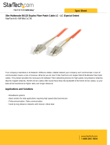
Figure 1-1. Front and Rear Panels
Switch Architecture
The FMS-24K employs a wire-speed, non-blocking switching fabric. This permits
simultaneous wire-speed transport of multiple packets at low latency on all ports.
This switch also features full-duplex capability on all ports, which effectively doubles
the bandwidth of each connection.
Auto-negotiation is used to select the optimal transmission speed and
communication mode for each connection. With store-and-forward switching and
flow control, maximum data integrity is always maintained, even under heavy
loading.
This switch includes two slots on the front panel for slide-in 1000BASE-LX,
1000BASE-SX, 1000BASE-T, 100BASE-FX, or 1000BASE-X (GBIC) modules.
Cascade connections between switches can be made using these modules.
The switch also supports a stacking module that can be installed into slot Module 2.
The stacking module allows up to eight units to be linked together and managed
from one unit using one IP address.
Media and Stacking Slots
System Indicators
10/100 Mbps RJ-45 Ports
Port Status Indicators (1-24)
Console Port
Module Status Indicators (25/26)
100-240V~
50/60Hz, 2A
Power Socket
Module 2 Module 1

About the Switch
1-2
Management Options
This switch contains a comprehensive array of LEDs for “at-a-glance” monitoring of
network and port status. It also includes a management agent that allows you to
configure or monitor the switch using its embedded management software, or via
SNMP applications. To manage the switch, you can make a direct connection to the
RS-232 console port (out-of-band), or you can manage the switch through a network
connection (in-band) using Telnet, the on-board Web agent, or Windows-based
network management software.
The management agent provides a wide range of advanced performance-enhancing
features. Port-based VLANs provide traffic security and efficient use of network
bandwidth. QoS priority queueing ensures the minimum delay for
moving real-time
multimedia data through the switch. Flow control
eliminates the loss of packets due to
bottlenecks caused by port saturation. Port security is provided to filter unwanted
traffic from the switch.
For a detailed description of the switch’s advanced features, refer to the
Management Guide.
Description of Hardware
RJ-45 Ports
The switch base unit contains 24 10BASE-T/100BASE-TX RJ-45 ports. All of these
ports support automatic MDI/MDI-X operation, so you can use straight-through
cables for all network connections to PCs or servers, or to other switches or hubs.
(See “10BASE-T/100BASE-TX Pin Assignments” on page B-2.)
Each of these ports support auto-negotiation, so the optimum transmission mode
(half or full duplex), and data rate (10 or 100 Mbps) can be selected automatically, if
this feature is also supported by the attached device. If a device connected to one of
these ports does not support auto-negotiation, the correct speed will be sensed by
the port, but the transmission mode will default to half duplex.
Each port also supports auto-negotiation of flow control, so the switch can
automatically prevent port buffers from becoming saturated.

Description of Hardware
1-3
Port Status LEDs
The base unit also includes a display panel for key system and port indications that
simplify installation and network troubleshooting. The LEDs, which are located on
the front panel for easy viewing, are shown below and described in the following
tables.
Figure 1-2. Port Status LEDs
Port Status LEDs
LED Condition Status
Base Unit Ports
1~24
(Link/Activity)
On/Flashing Amber Port has established a valid 10 Mbps network connection.
Flashing indicates activity.
On/Flashing Green Port has established a valid 100 Mbps network connection.
Flashing indicates activity.
Off There is no valid link on the port.
Module Ports
25, 26
(Link/Activity)
On/Flashing Amber Port has established a valid 10/100 Mbps network
connection. Flashing indicates activity.
On/Flashing Green Port has established a valid 1000 Mbps network
connection. Flashing indicates activity.
Off There is no valid link on the port.

About the Switch
1-4
System Status LEDs
Figure 1-3. System Status LEDs
System Status LEDs
LED Condition Status
PWR On Green The unit’s internal power supply is operating normally.
On Amber The unit’s internal power supply has failed.
Off The unit has no power connected.
Diag On Green The system diagnostic test has completed successfully.
Flashing Green The system diagnostic test is in progress.
On Amber The system diagnostic test has detected a fault.
Link N/A This indicator is not currently implemented.
Duplex N/A This indicator is not currently implemented.
Stack
Flashing Amber An initial state of stacking configuration upon powering on.
Green This switch is acting as the master unit in the stack.
Amber This switch is acting as a slave unit in the stack.
Flashing Green
When the user enters the light unit command in the CLI,
the unit ID of each switch in the stack will be displayed by
port LEDs 1 to 8.
Link
Duplex
M1
M2
PWR
Diag
Stack
Module 1
RPU

Description of Hardware
1-5
Optional Media Extender Modules
Optional 1000BASE-T Module
Figure 1-4. Single-Port 1000BASE-T Module
Using Category 5, 5e, or 6 twisted-pair cable you can connect to another device up
to 100 m (328 ft) away. The 1000BASE-T module operates at 10/100/1000 Mbps. At
1000 Mbps it operates at full duplex and supports auto-negotiation of speed and
flow control. At 10/100 Mbps it supports auto-negotiation of speed, duplex mode
(i.e., half or full duplex), and flow control. Note that you should first test the cable
installation for IEEE 802.3ab compliance. See “1000BASE-T Cable Requirements”
on page B-5.
Optional 1000BASE-SX Module
Figure 1-5. Single-Port 1000BASE-SX Gigabit Module
Using multimode fiber optic cable, the 1000BASE-SX port can be connected to a
remote site up to 550 m (1805 ft) away. The 1000BASE-SX Gigabit module operates
at 1 Gbps, with support for full-duplex mode and flow control.
Optional 1000BASE-LX Module
Figure 1-6. Single-Port 1000BASE-LX Gigabit Module
1000BASE-T RJ45 Module
1000BASE-SX Multimode Module
RX
TX
100BASE-FX Singlemode Module
TX
RX
1000BASE-LX Singlemode Module
RX
TX

About the Switch
1-6
Using single-mode fiber optic cable, the 1000BASE-LX port can be connected to a
remote site up to 5 km (16404 ft) away. The 1000BASE-LX Gigabit module operates
at 1 Gbps, with support for full-duplex mode and flow control.
Optional 100BASE-FX Multimode Module
Figure 1-7. Single-Port 100BASE-FX Multimode Module
Using multimode fiber optic cable, the 100BASE-FX port can be connected to a
remote site up to 2 km (1.24 miles) away. The 100BASE-FX module is fixed to
operate at 100 Mbps full duplex, and supports auto-negotiation for flow control. The
module is fitted with an SC connector.
Optional 100BASE-FX Single-mode Module
Figure 1-8. Single-Port 100BASE-FX Single-mode Module
Using fiber optic cable, the 100BASE-FX port can be connected to a remote site up
to 20 km (12.43 miles) away. The 100BASE-FX module is fixed to operate at
100 Mbps full duplex, and supports auto-negotiation for flow control. The module is
fitted with an SC connector.
Optional 1000BASE-X GBIC Module
Figure 1-9. Single Port 1000BASE-X GBIC Module
100BASE-FX Multimode Module
TX
RX
100BASE-FX Singlemode Module
TX
RX
1000BASE-X GBIC Module

Description of Hardware
1-7
This module supports 5 V 1000BASE-SX, 1000BASE-LX and 1000BASE-LH GBIC
transceivers:
1000BASE-SX GBIC transceivers provide one short-wavelength (850 nm) Gigabit
port that can be used for a high-speed backbone or server connection. This port can
be connected to a site up to 220 m (722 ft) away with 62.5/125 micron multimode
fiber cable, or up to 500 m (1641 ft) with 50/125 micron multimode fiber cable.
1000BASE-LX GBIC transceivers provide one long-wavelength (1300 nm) Gigabit
port that can be used for a high-speed backbone or server connection. This port can
be connected to a site up to 5 km (16404 ft) away with single-mode fiber cable.
1000BASE-LH GBIC transceivers provide one long-wavelength (1550 nm) Gigabit
port that can be used for a long-haul connection to a remote location. This port can
be connected to a site up to 70 km (43.5 miles) away with single-mode fiber cable.
Caution: Install only 5 V GBIC transceivers into the module slots.
Optional Stacking Module
Figure 1-10. Stacking Module
The module provides two 1 Gbps ports via USB Type-A connectors. The right port is
a transmit port and the one on the left a receive port. The module allows up to eight
switches to be linked together using stacking cables (ordered separately). The push
button on the module enables one switch in the stack to be selected as the master.
Combo Module
Figure 1-11. Combo Module
This combo module provides a Gigabit RJ-45 port with a shared Small Form Factor
Pluggable (SFP) transceiver slot. If an SFP transceiver (purchased separately) is
installed in a slot and has a valid link on the port, the associated RJ-45 port is
Stacking Module
RX TX
1000BASE Combo Module

About the Switch
1-8
disabled.
To connect a device to an SFP port, do the following:
1. Use your cabling requirements to select an appropriate SFP transceiver type.
2. Insert the SFP transceiver (sold separately) into an SFP slot. The slot’s LED
indicator turns on to confirm that it is correctly installed.
The 1000BASE-T RJ-45 ports support automatic MDI/MDI-X operation, so you can
use straight-through cables for all network connections to PCs or servers, or to other
switches or hubs. (See “10BASE-T/100BASE-TX Pin Assignments” on page B-2.)
Power Supply Receptacle
The power receptacle is located on the rear panel of the switch. The standard power
receptacle is for the AC power cord.
Figure 1-12. Power Supply Receptacle
100-240V~
50/60Hz, 2A
/