Page is loading ...

Industrial Flow Monitor
Series 3100
CTL-UM-01026-EN-05 (October 2017)
User Manual

Industrial Flow Monitor, Series 3100
Page ii October 2017CTL-UM-01026-EN-05

CONTENTS
Introduction. . . . . . . . . . . . . . . . . . . . . . . . . . . . . . . . . . . . . . . . . . . . . . . . . . . . . . . . . . . . . . . . . . . . . . . . . .5
Advanced Standard Features . . . . . . . . . . . . . . . . . . . . . . . . . . . . . . . . . . . . . . . . . . . . . . . . . . . . . . . . . . . .5
Safety Information. . . . . . . . . . . . . . . . . . . . . . . . . . . . . . . . . . . . . . . . . . . . . . . . . . . . . . . . . . . . . . . . . . . . . .5
Unpacking & Inspection . . . . . . . . . . . . . . . . . . . . . . . . . . . . . . . . . . . . . . . . . . . . . . . . . . . . . . . . . . . . . . . . . . 6
Installation. . . . . . . . . . . . . . . . . . . . . . . . . . . . . . . . . . . . . . . . . . . . . . . . . . . . . . . . . . . . . . . . . . . . . . . . . . .6
Mechanical . . . . . . . . . . . . . . . . . . . . . . . . . . . . . . . . . . . . . . . . . . . . . . . . . . . . . . . . . . . . . . . . . . . . . . . 6
Location . . . . . . . . . . . . . . . . . . . . . . . . . . . . . . . . . . . . . . . . . . . . . . . . . . . . . . . . . . . . . . . . . . . . . . 6
Panel Mount Installation . . . . . . . . . . . . . . . . . . . . . . . . . . . . . . . . . . . . . . . . . . . . . . . . . . . . . . . . . . . 6
Wall Mount Installation . . . . . . . . . . . . . . . . . . . . . . . . . . . . . . . . . . . . . . . . . . . . . . . . . . . . . . . . . . . . 7
Electrical Power. . . . . . . . . . . . . . . . . . . . . . . . . . . . . . . . . . . . . . . . . . . . . . . . . . . . . . . . . . . . . . . . . . . . .7
Low Voltage 12…24V AC/DC Wiring . . . . . . . . . . . . . . . . . . . . . . . . . . . . . . . . . . . . . . . . . . . . . . . . . . . . 7
High Voltage Power Supply Wiring . . . . . . . . . . . . . . . . . . . . . . . . . . . . . . . . . . . . . . . . . . . . . . . . . . . . . 7
Input Sensor Wiring . . . . . . . . . . . . . . . . . . . . . . . . . . . . . . . . . . . . . . . . . . . . . . . . . . . . . . . . . . . . . . . . . . 8
Pulse Inputs (Solid-State Switch or Sine Wave). . . . . . . . . . . . . . . . . . . . . . . . . . . . . . . . . . . . . . . . . . . . . . 8
Analog Input . . . . . . . . . . . . . . . . . . . . . . . . . . . . . . . . . . . . . . . . . . . . . . . . . . . . . . . . . . . . . . . . . . . 9
Output Wiring. . . . . . . . . . . . . . . . . . . . . . . . . . . . . . . . . . . . . . . . . . . . . . . . . . . . . . . . . . . . . . . . . . . . . .9
Mechanical Form C Relays (COM, N.O. and N.C.). . . . . . . . . . . . . . . . . . . . . . . . . . . . . . . . . . . . . . . . . . . . . 9
Normally Open Solid-State Switch . . . . . . . . . . . . . . . . . . . . . . . . . . . . . . . . . . . . . . . . . . . . . . . . . . . . .11
Analog Outputs . . . . . . . . . . . . . . . . . . . . . . . . . . . . . . . . . . . . . . . . . . . . . . . . . . . . . . . . . . . . . . . . .11
RS485 Communication Wiring . . . . . . . . . . . . . . . . . . . . . . . . . . . . . . . . . . . . . . . . . . . . . . . . . . . . . . . .12
USB Communications Port . . . . . . . . . . . . . . . . . . . . . . . . . . . . . . . . . . . . . . . . . . . . . . . . . . . . . . . . . .12
Keypad/Display Menu Navigation . . . . . . . . . . . . . . . . . . . . . . . . . . . . . . . . . . . . . . . . . . . . . . . . . . . . . . . . 13
Programming . . . . . . . . . . . . . . . . . . . . . . . . . . . . . . . . . . . . . . . . . . . . . . . . . . . . . . . . . . . . . . . . . . . . . . . .14
Selection Screens . . . . . . . . . . . . . . . . . . . . . . . . . . . . . . . . . . . . . . . . . . . . . . . . . . . . . . . . . . . . . . . .14
Option List Screens . . . . . . . . . . . . . . . . . . . . . . . . . . . . . . . . . . . . . . . . . . . . . . . . . . . . . . . . . . . . . . .14
Data Entry Screens . . . . . . . . . . . . . . . . . . . . . . . . . . . . . . . . . . . . . . . . . . . . . . . . . . . . . . . . . . . . . . .14
Programming Flowchart . . . . . . . . . . . . . . . . . . . . . . . . . . . . . . . . . . . . . . . . . . . . . . . . . . . . . . . . . . . . . . 16
Flow Inputs Flowchart . . . . . . . . . . . . . . . . . . . . . . . . . . . . . . . . . . . . . . . . . . . . . . . . . . . . . . . . . . . . . . . 18
Relays and Pulse Outputs Flowchart. . . . . . . . . . . . . . . . . . . . . . . . . . . . . . . . . . . . . . . . . . . . . . . . . . . . . . .20
Analog Outputs Flowchart. . . . . . . . . . . . . . . . . . . . . . . . . . . . . . . . . . . . . . . . . . . . . . . . . . . . . . . . . . . . .21
User Manual
Page iii October 2017 CTL-UM-01026-EN-05

RS485 Communication Flowchart . . . . . . . . . . . . . . . . . . . . . . . . . . . . . . . . . . . . . . . . . . . . . . . . . . . . . . . . 22
Solid-State Switch and Form C Outputs . . . . . . . . . . . . . . . . . . . . . . . . . . . . . . . . . . . . . . . . . . . . . . . . . . . . 23
Totalizer Pulse Output . . . . . . . . . . . . . . . . . . . . . . . . . . . . . . . . . . . . . . . . . . . . . . . . . . . . . . . . . . . . .23
Setpoints . . . . . . . . . . . . . . . . . . . . . . . . . . . . . . . . . . . . . . . . . . . . . . . . . . . . . . . . . . . . . . . . . . . . .23
Communication . . . . . . . . . . . . . . . . . . . . . . . . . . . . . . . . . . . . . . . . . . . . . . . . . . . . . . . . . . . . . . . . . . . 24
RS485 COM Port Conguration . . . . . . . . . . . . . . . . . . . . . . . . . . . . . . . . . . . . . . . . . . . . . . . . . . . . . . .24
Modbus . . . . . . . . . . . . . . . . . . . . . . . . . . . . . . . . . . . . . . . . . . . . . . . . . . . . . . . . . . . . . . . . . . . . . .24
BACnet. . . . . . . . . . . . . . . . . . . . . . . . . . . . . . . . . . . . . . . . . . . . . . . . . . . . . . . . . . . . . . . . . . . . . . .25
USB Command List . . . . . . . . . . . . . . . . . . . . . . . . . . . . . . . . . . . . . . . . . . . . . . . . . . . . . . . . . . . . . . .26
Troubleshooting . . . . . . . . . . . . . . . . . . . . . . . . . . . . . . . . . . . . . . . . . . . . . . . . . . . . . . . . . . . . . . . . . . . . . . 29
Trouble Codes. . . . . . . . . . . . . . . . . . . . . . . . . . . . . . . . . . . . . . . . . . . . . . . . . . . . . . . . . . . . . . . . . . . . .29
Specications. . . . . . . . . . . . . . . . . . . . . . . . . . . . . . . . . . . . . . . . . . . . . . . . . . . . . . . . . . . . . . . . . . . . . . . .30
Ordering Matrix . . . . . . . . . . . . . . . . . . . . . . . . . . . . . . . . . . . . . . . . . . . . . . . . . . . . . . . . . . . . . . . . . . . . . . 31
Industrial Flow Monitor, Series 3100
Page iv October 2017CTL-UM-01026-EN-05

INTRODUCTION
The Badger Meter® Data Industrial® Series 3100 flow monitor is an economical, dual channel, full featured, digital rate and
totalizing monitor, compete with setpoint control, scaled pulse output, analog outputs, analog PID controller, USB, and RS485
Modbus and BACnet communication.
Panel mount is Type NEMA 4X, and conforms to DIN standard dimensions (96 mm × 96 mm) for meter size and panel cutout.
An optional Type NEMA 4 wall mount will be available in the future.
The back-lit, two-line by 16-character alphanumeric display can be configured by the user with factory preset or with
user-defined units of measure. Any combination of two rates or totals from either input channel can be displayed at any one
time, with the special feature of channel addition or subtraction. LEDs report relay status and digital communication.
Inputs are from any combination of two pulse, sine wave or linear analog input devices.
Configuration is menu driven using the LCD/keypad interface, or USB computer connection, with multiple password gates to
prevent unauthorized access, while allowing access to select features such as total and relay reset functions.
Outputs include four Form C mechanical relays, one solid-state switch, two Analog Outputs, one USB, and one RS485 with
BACnet and Modbus protocols.
Advanced Standard Features
• Easy to switch power supplies from 12…24V AC/DC to the optional 120/240V AC
• Nonvolatile memory; no battery backup is required
• Two independent pulse and analog input channels can be used separately or combined in addition or subtraction modes,
for all display output functions
• Field-definable custom units of measure labeling and conversion factors
• Two line by 16-character 3/8 in. (7.95 mm) high back-lit display
• Front panel LEDs indicate status of each relay, pulse output, and Rx/Tx activity
• Simple front panel configuration with the option to use the USB port
• USB communication is a very powerful diagnostic and OEM tool
• Two-level password protection; one to restrict setup access and one to protect totals
• Field-definable custom units of measure labeling and conversion factors
• A total of seven independent relay, pulse and analog outputs
• Powerful setpoint control, with independent set and release point values, set and release delays, and latching functions
• Scaled pulse output with pulse width control
• Dual channel analog outputs are either current sinking or sourcing 4…20 mA or 0…20 mA. Current sourcing 0…20 mA
permits external conversion to 0…5V DC or 0…10V DC
• PID process control using analog outputs
• RS485 with Modbus and BACnet/MSTP protocols
• IIRF (Infinite impulse response filter). Proprietary input signal smoothing
SAFETY INFORMATION
The installation of the flow monitor must comply with all applicable federal, state, and local rules, regulations, and codes.
Failure to read and follow these instructions can lead to misapplication or misuse of the flow monitor, resulting in personal
injury and damage to equipment.
Introduction
Page 5 October 2017 CTL-UM-01026-EN-05

UNPACKING & INSPECTION
Upon opening the shipping container, visually inspect the product and applicable accessories for any physical damage such
as scratches, loose or broken parts, or any other sign of damage that may have occurred during shipment.
OTE:N If damage is found, request an inspection by the carrier’s agent within 48 hours of delivery and file a claim with the
carrier. A claim for equipment damage in transit is the sole responsibility of the purchaser.
INSTALLATION
Mechanical
The Series 3100 flow monitor can be either panel mounted or wall mounted.
Location
In any mounting arrangement, the primary concern is easy viewing and convenient keypad operation. The flow monitor
generates very little heat, so no consideration need be given to cooling or ventilation. However, prolonged direct sunlight can
damage the front panel so some level of shading is recommended, especially if installed in a tropical climate.
Panel Mount Installation
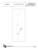
The Series 3100 panel mount monitor is designed for through-panel mounting, which allows access to the back of the unit.
The monitor is secured to the panel by two draw brackets.
Figure 1: Panel mounting
Menu
Enter
Series 3100
TX RX
Pulse Out
Relay 4Relay 3
Relay 2
Relay 1
Industrial
Data
A BadgerMeter, Inc. Company
R
3.57 in. to 3.60 in.
(90.6 mm to 91.4 mm)
3.57 in. to 3.60 in.
(90.6 mm to 91.4 mm)
Panel Cutout
3.49 in.
(88.7 mm)
4.31 in.
(109 mm)
4.79 in.
(122 mm)
3.78 in.
(96 mm)
3.49 in.
(88.7 mm)
3.78 in.
(96 mm)
Figure 2: Physical dimensions and panel cutout
Unpacking & Inspection
Page 6 October 2017CTL-UM-01026-EN-05

Wall Mount Installation
Badger Meter does not currently offer a wall mount enclosure for this product. However, Series 3100 flow monitors can be
wall mounted in the field into any appropriate customer-supplied enclosure.
Electrical Power
MPORTANTI
Before applying power to this unit, check the Model # label: The Series 3100 flow monitor can be ordered as low voltage 12…24V AC/
DC (3100-0x) or as high voltage 120/240V AC (3100-1x).
Low Voltage 12…24V AC/DC Wiring
The Series 3100 flow monitor has a green, three-terminal connector with screw heads, and requires 12…24V AC/DC to
operate. See "Specifications" on page 30 for the current DC draw and AC Volt-Amp requirements. Always use a fused circuit.
Connect the positive end of the power supply to the Series 3100 flow monitor terminal marked LV AC/DC (+), and connect
the negative end of the power supply to the Series 3100 flow monitor terminal marked LV AC/DC (–). Earth ground can be
connected to the terminal marked EARTH.
Ground should be heavy gauge wire and as
short as possible.
If panel mounting in a metal enclosure,
Ground to door and bond the door to the
enclosure across the hinges with a brad
just long enough to allow the door to
open freely.
Orange Label
Earth Ground
LV AC/DC (+)
LV AC/DC (-)
3
2
1
AC AC
12 . . . 24V AC
Power Supply
(+) (-)
12 . . . 24V DC
Power Supply
Either AC or DC power can be used.
AC is not polarity sensitive.
Figure 3: Series 3100-0x low voltage power supply wiring
High Voltage Power Supply Wiring
The Series 3100-1x is designed to accept a standard EL-712 (NEMA 5-15R) plug similar to those used on many laptop
computers. Power can be 120…240V AC 50…60 Hz. When the High Voltage option is ordered (3100-1x), a power cord is
supplied with the unit.
See "Specifications" on page 30 for volt/amp ratings for inverter or other non-conventional source.
Installation
Page 7 October 2017 CTL-UM-01026-EN-05

Input Sensor Wiring
The Series 3100 flow monitor is a Dual Channel unit. Either a single input, or any combination of two pulse or analog inputs
can be used. The pulse inputs are extremely versatile, designed to accept either two-wire (Data Industrial 200 Series), three-
wire pulse inputs (4000 Series) or zero-crossing sine wave inputs (turbines with a magnetic coil pickup).
The analog inputs can accept 0…20 mA, 4…20 mA, 0…1V DC, 0…5V DC or 0…10V DC. Both the top and bottom ends of the
analog range can be configured in the field so that most inputs can be accepted if the hardware limitations are not exceeded.
Contact the factory for assistance with custom inputs. Although different rear panel terminals are used, all parameters are set
with the LCD/keypad interface. No internal or external jumpers, switches or potentiometers require movement or adjustment.
Pulse Inputs (Solid-State Switch or Sine Wave)
The Series 3100 flow monitor accommodates four types of pulse inputs:
• Pulse-DI: Used for all Data Industrial Flow Sensors. Provides an internal pullup resistor and uses “K” and “Offset” values
for calibration.
• Pulse –K Factor: Accepts non Zero Crossing inputs but provides no internal pullup, classical “K” (pulses/gal) values
for calibration.
• Pullup K Factor: Provides an internal pullup resistor and uses classical “K” ( pulses/gal) values for calibration.
• Sine-K Factor: Accepts zero crossing low voltage sourcing devices, with classical “K” ( pulses/gal) calibration.
Channel #1
Two Wire Flow Sensor
Sensor (+)
Sensor (-)
Shield
Shield
Sensor (+)
Sensor (-)
Channel #2
Two Wire Flow Sensor
Analog 1 IN (+) 1
Analog 1 IN (-) 2
Shield 3
Analog 2 IN (+) 4
Analog 2 IN (-) 5
Shield 6
Pulse 1 IN (+) 7
Pulse1 IN (-) 8
Shield 9
Pulse 2 IN (+) 10
Pulse 2 IN (-) 11
Sensor Power 12
Sensor Input Card
Green Label
12 Pin Connector
200 Series Flow Sensors
Red = Sensor (+)
Black = Sensor (-)
SDI Series Sensors
Varies with Model
Refer to SDI User Manual
Other Sensors
Contact Technical Support as needed
Figure 4: Wiring a two-wire pulse flow sensor
4000 Series Flow Sensors
Red = Sensor Power
White = Sensor (+)
Black = Sensor (-)
SDI Series Sensors
Varies with Model
Refer to SDI User Manual
Other Sensors
Contact Technical Support as needed
Channel #1
Three Wire Flow Sensor
Sensor Power
Sensor (+)
Sensor (-)
Shield
Shield
Sensor (+)
Sensor (-)
Channel #2
Three Wire Flow Sensor
Sensor Power
Analog 1 IN (+) 1
Analog 1 IN (-) 2
Shield 3
Analog 2 IN (+) 4
Analog 2 IN (-) 5
Shield 6
Pulse 1 IN (+) 7
Pulse1 IN (-) 8
Shield 9
Pulse 2 IN (+) 10
Pulse 2 IN (-) 11
Sensor Power 12
Sensor Input Card
Green Label
12 Pin Connector
Figure 5: Wiring a three-wire pulse sensor
Installation
Page 8 October 2017CTL-UM-01026-EN-05

Analog Input
As an alternative to the pulse inputs, the Badger Meter Series 3100 also accepts up to two analog inputs. The input is
non-isolated, but can accept 0…1V DC, 0…5V DC, 0…10V DC, 0…20 mA and 4…20 mA with both factory-defined and
custom units of measure. Low impedance 100 Ohm input for current inputs optimizes performance and flexibility for loop
power supplies. Both the low and high end scaling are independent and field-configured by the installer.
Channel #1
Loop Powered Sensor
Loop (-)
Loop (+)
Shield
External
24V DC
Power
Supply
(+)
(-)
Voltage or Current Sourcing Device
with internal Power Supply
Voltage/Current (+)
Shield
Voltage/Current Com
Analog 1 IN (+) 1
Analog 1 IN (-) 2
Shield 3
Analog 2 IN (+) 4
Analog 2 IN (-) 5
Shield 6
Pulse 1 IN (+) 7
Pulse1 IN (-) 8
Shield 9
Pulse 2 IN (+) 10
Pulse 2 IN (-) 11
Sensor Power 12
Sensor Input Card
Green Label
12 Pin Connector
NOTES:
1. Analog Inputs share an isolated ground from power supply and earth grounds; however, Channel #1 and #2 share a single ground plane.
2. Input ranges of 0 . . . 1V DC, 0 . . . 5V DC, 0 . . . 10V DC, 1 . . . 20 mA, or 4 . . . 20 mA can be selected from front panel or via USB communication port.
3. Voltage inputs are high impedance 100 K +. Current inputs are 100 Ohm. As a result, a 4 . . . 40 mA input will appear as 0.2V DC to 2.0V DC across
the Analong Input Terminals. This information can be helpful in troubleshooting.
Figure 6: Wiring current and voltage sourcing inputs
Output Wiring
The Series 3100 flow monitor has four mechanical Form C relays, one solid-state, normally open (N.O.) switch closure, two
analog outputs, RS485 for Modbus and BACnet communications and a USB connector for configuration and other purposes.
See "Specifications" on page 30 for maximum voltage and current ratings for each output type.
Mechanical Form C Relays (COM, N.O. and N.C.)
The four Form C mechanical relays are labeled N.O., N.C. (normally closed) and COM (common).
When a relay is de-energized, the corresponding LED is unlit, and continuity exists between N.C. and COM; and N.O. to COM
is open.
When a relay is energized, the corresponding LED lights yellow and there is continuity between N.O. and COM and N.C. to
COM is open.
Installation
Page 9 October 2017 CTL-UM-01026-EN-05

Normally Open
Master Valve
Power Supply
(Appropriate for Master Valve)
Typically 24V DC
(COM) (Line)
Relay 1 NO
Relay 1 NC
Relay 1 COM
Relay 2 NO
Relay 2 NC
Relay 2 COM
Relay 3 NO
Relay 3 NC
Relay 3 COM
Relay 4 NO
Relay 4 NC
Relay 4 COM
Pulse 1 OUT
Pulse 1 OUT
Sensor Input Card
Red Label
14 Pin Connector
1
2
3
4
5
6
7
8
9
10
11
12
13
14
Indicator Light
or other
Signaling Device
Figure 7: High flow shutdown and normally open master valve
Normally Closed
Master Valve
Irrigation Controller
(COM) (Master Valve Out)
Relay 1 NO
Relay 1 NC
Relay 1 COM
Relay 2 NO
Relay 2 NC
Relay 2 COM
Relay 3 NO
Relay 3 NC
Relay 3 COM
Relay 4 NO
Relay 4 NC
Relay 4 COM
Pulse 1 OUT
Pulse 1 OUT
Sensor Input Card
Red Label
14 Pin Connector
1
2
3
4
5
6
7
8
9
10
11
12
13
14
Indicator Light
or other
Signaling Device
NOTE: Relay pregrammed for the desired Set Point and Set Delay, and LATCHED.
Under normal conditions, the relay simply passes the commands of the irrigation controller through the Normally Open contact.
However, once tripped, the Irrigation Controller signal is simply passed to the signalling device to warn the operators.
Figure 8: High flow shutdown with irrigation clock and normally closed master valve
Installation
Page 10 October 2017CTL-UM-01026-EN-05

Normally Open Solid-State Switch
Mechanical
Counter
Power Supply
(Appropriate Mechanical Counter)
Typically 12V DC
(-) (+)
Relay 1 NO
Relay 1 NC
Relay 1 COM
Relay 2 NO
Relay 2 NC
Relay 2 COM
Relay 3 NO
Relay 3 NC
Relay 3 COM
Relay 4 NO
Relay 4 NC
Relay 4 COM
Pulse 1 OUT
Pulse 1 OUT
Sensor Input Card
Red Label
14 Pin Connector
NOTE:
Although the example shown here is showing the Pulse Output as a Pulse/Unit Volume, this output is a fully functional relay,
with all the programming feature of the four mechanical relays. However, instead of a Form C mechanical, it is a Form A Solid-State Switch (NO).
1
2
3
4
5
6
7
8
9
10
11
12
13
14
Figure 9: External mechanical counter and power supply
The pulse output is a completely programmable, isolated N.O. solid-state switch.
It is a non-polarized device that can handle either DC or AC loads. See "Specifications" on page 30 for voltage and
load limitations.
Analog Outputs
The Series 3100 flow monitor has two analog outputs. Each is isolated and independent and can be configured for 0…20 mA
or 4…20 mA. This unique design permits external conversion to 0…5V DC or 1…5V DC with a 250 Ohm resistor or 0…10V DC
or 2…10V DC with a 500 Ohm resistor.
A 15V DC power supply to permits current sinking or sourcing. If additional source voltage is required, an external source of
up to 30V DC can be used.
Analog Input Device
12V max. @20 mA
Analog (+)
Analog (-)
NOTE:
Resistor only required
for voltage input devices
0 . . . 1V DC, 0 . . . 5V DC,
1 . . . 5V DC, 2 . . . 10V DC, etc.
0 . . . 20 mA and 4 . . . 20 mA
devices do not use an
external resistor.
Analog Input Device
with External or Integral
Power Supply
24V DC (+)
Analog IN (+)
Analog IN (-)
Power Supply COM
Analog Output Card
Yellow Label
9 Pin Connector
R
e
s
i
s
t
o
r
RS485 B (+)
RS385 A (-)
RS485 Iso. GND (REF)
CH2 Loop (+)
CH2 Loop (-)
CH2 GND
CH1 Loop (+)
CH1 Loop (-)
CH1 GND
1
2
3
4
5
6
7
8
9
NOTES:
4 . . . 20 mA input devices only require that
the 4 . . . 20 mA range be selected.
0 . . . 1V DC requires 0 . . . 20 mA range and
external 50 Ohm resistor.
0 . . . 5V DC requires 0 . . . 20 mA range and
external 250 Ohm resistor.
2 . . . 10V DC requires 0 . . . 20 mA range and
external 500 Ohm resistor.
1.
2. Loop (+) is +15V DC power our.
Loop (-) is a current sink to CHx GND.
CHx GND is the +15V reference.
3. Analog Out #1 and Analog #2 are totally
independent but are programmed and
wired identically, and can be used
interchangeably. For example, one
can be 0 . . . 20 mA and the other
4 . . . 20 mA; or one could be wired
current sinking while the other is
wired current sourcing.
The Output Channels are assigned to an
Input Channel by the installer. Both Output
Channels can be assigned to the same
Input Channel.
Figure 10: Current sourcing analog output to voltage input device
Installation
Page 11 October 2017 CTL-UM-01026-EN-05

RS485 Communication Wiring
Analog Output Card
Yellow Label
9 Pin Connector
RS485 B (+)
RS385 A (-)
RS485 Iso. GND (REF)
CH2 Loop (+)
CH2 Loop (-)
CH2 GND
CH1 Loop (+)
CH1 Loop (-)
CH1 GND
1
2
3
4
5
6
7
8
9
RS485 (+)
RS485 (-)
Shield
Series 3700 or other
Modbus or BACnet
Master Device
Figure 11: RS485 communication wiring (Modbus + BACnet)
USB Communications Port
Using the USB Port requires Windows® HyperTerminal or other similar communications software.
Use Standard Cable
USB Type A Male
to
Type Mini B 5-Pin Male
Connect to Computer
USB COM Port
Figure 12: USB port
Installation
Page 12 October 2017CTL-UM-01026-EN-05

Keypad/Display Menu Navigation
The Series 3100 flow monitor has a two line by 16-character display with two modes of operation and 5 keys on the front
panel for programming. Two of the keys (Menu and Enter) serve a single function while the three remaining keys ()
serve dual purposes.
When the flow monitor is first powered up, it performs internal testing while displaying “Badger Meter DIC Initializing.” At the
end of the internal testing cycle, the main display appears.
In the normal mode, using the factory defaults, the flow rate displays on the top line and the flow total displays on the
bottom. Both lines can be custom defined in the field. In the normal mode, ENTER has no function.
Flow Channel 1 Flow Rate and Flow Total
1 123.00 GPM
1 123456.7 gal
Flow Channel 1 Flow Rate and Flow Total
Flow Channel 1 Flow Rate and Flow Channel 2 Rate
1 123.00 GPM
2 123456.70 GPM
Flow Channel 1 Flow Rate and Flow Channel 2 Rate
Channel 2: Pressure and Channel 1: Level
2 10.01 PSI
1 23.09 Feet
Channel 2: Pressure and Channel 1: Level
Main Set-up screen accessed by pressing the “MENU” Button
One each screen there are three Choices
(In this case RESET SETUP and DIAG)
▲ selects RESET ▼ selects SETUP and ► selects DIAG
RESET SETUP DIAG
Main Setup screen accessed by pressing MENU.
On each screen there are three options:
selects RESET selects SETUP and selects DIAG
As seen in the previous figure, on every screen there are Three
Choices, and three corresponding buttons. However, on this menu
“Set-up” there are more choices than fit on the screen. The is
indicated by the “ →”. To access these remaining choices press the
“Enter” Button.
SETUP →
PWORD DSPY FLOW1
On every screen there are three choices and three
corresponding buttons. However, on this Setup menu there
are more options than t on the screen. The arrow ()
indicates additional options. To access these remaining
options, press ENTER.
Pressing the “Enter” button again brings up the next set of choices,
and so on.
Pressing “MENU” button exits section, back to the previous
screen, or in some cases back to the Main display screen.
SETUP →
FLOW1 RLY1 RLY2
Press ENTER again to bring up the next set of choices.
Press MENU to exit an option, or return to the previous
screen, or—in some cases—to return to the main
display screen.
Installation
Page 13 October 2017 CTL-UM-01026-EN-05

PROGRAMMING
Selection Screens
Press MENU while the normal display is shown to access the programming mode. In this mode, press one of the three arrow
keys () to select the option displayed above that key. On option list screens, use the arrows to scroll through a list of
choices, like a pull-down menu. Note that most screens presenting choices show three choices, one for each arrow button.
When the number of choices exceeds three, a small arrow () appears in the upper right side of the display to indicate more
choices on that level. Press ENTER to toggle to the next set of choices. Once a selection has been made, press ENTER to
complete the selection. Press MENU to return to the Normal screen. For example: Press MENU from the Normal screen to
display the “RESET SETUP DIAG” screen.
Press to display the Reset screens, to display the Setup screens and to display the Diagnostic screens. If is pressed,
the following screen appears:
6.1SelectionScreens
6.2OptionListScreens
6.3DataScreens
SETUP
PWORD DSPY FLOW1
Menu Enter
Flow 1 units
GPM
Menu Enter
Set poin
t
1.0000000
0
Menu Enter
Figure 13: Selection screen
Option List Screens
Units of measure is an example of an options list.
Press to scroll up the list, and to scroll down through the list. In this case, starting with GPM; gal/s; gal/hr; LPM; ending in
a selection of custom units. Press ENTER to complete the selection. Press MENU to leave the selection unchanged.
The key has no function on this type of screen.
6.1SelectionScreens
6.2OptionListScreens
6.3DataScreens
SETUP
PWORD DSPY FLOW1
Menu Enter
Flow 1 units
GPM
Menu Enter
Set poin
t
1.0000000
0
Menu Enter
Figure 14: Options list screen
Data Entry Screens
Some screens are data entry screens, such as setpoints or custom units. When a data screen is initially displayed, the current
value will be displayed. The cursor will be flashing the left-most digit. Press to increase a value, and to reduce a value.
If the cursor is flashing on the decimal point, press to move the decimal point to the right, press to move the decimal to
the left.
6.1SelectionScreens
6.2OptionListScreens
6.3DataScreens
SETUP
PWORD DSPY FLOW1
Menu Enter
Flow 1 units
GPM
Menu Enter
Set poin
t
1.0000000
0
Menu Enter
Figure 15: Data entry screen
Programming
Page 14 October 2017CTL-UM-01026-EN-05

User Manual
INTENTIONAL BLANK PAGE
Page 15 October 2017 CTL-UM-01026-EN-05

Programming Flowchart
Enter password
0000
RESET SETUP DIAG
RESET
FLOW1 FLOW2
Reset ow x?
OK CANCEL
Enter password
0000
Reset ow x?
RESET
Password setup
ENAB SETUP RESET
Require setup PW
YES [NO]
SETUP
PWORD DSPY FLOW1
Reset password
0000
Set Up password
0000
Display
LINE1 LINE2 RATE
LINE1
Flow 1 Rate
Flow 1 Total
Flow 2 Rate
Flow 2 Total
Flow 1 +2 Rate
Flow 1 +2 Total
Flow 1 -2 Rate
Flow 1 -2 Total
Flow 2 -1 Rate
Flow 2 -1 Total
Update rate
+0.00000000 sec
.
.
.
+9.99999999 sec
Appears only if
Setup Password is enabled.
LINE1
Flow 1 Rate
Flow 1 Total
Flow 2 Rate
Flow 2 Total
Flow 1 +2 Rate
Flow 1 +2 Total
Flow 1 -2 Rate
Flow 1 -2 Total
Flow 2 -1 Rate
Flow 2 -1 Total
Batch password
0000
Continued at A
on next page.
Continued at B
on next page.
Programming
Page 16 October 2017CTL-UM-01026-EN-05

Programming Flowchart (continued)
DIAG
MODL# SER# REV#
RESET SETUP DIAG
SETUP
PWORD DSPY FLOW1
DIAG
ERROR
Model #
3100XX
Firmware rev:
v1.2.29
Serial #
XXXXXX
Error codes:
000 000 000 000
SETUP
RLY3 RLY4 Pulse
SETUP
AOUT1 AOUT2 COMM
Go to RS485
MODBUS/BACnet
Go to
Analog
Outputs
Go to
Relays & Pulse
Outputs
Go to
Flow
Inputs
SETUP
FLOW2 RLY1 RLY2
Continued from A
on previous page.
Continued from B
on previous page.
Programming
Page 17 October 2017 CTL-UM-01026-EN-05

Flow Inputs Flowchart
Continued
at A on
next page.
Flow 1 setup
RATE TOTAL SENSR
Flow 1 # digits
0
1
2
Custom units
LABEL CONV
1 UNIT =
-0.00000000 GPM
.
.
.
+999999999. GPM
Flow X rate
UNITS #.DIG CUST
Flow x units
GPM
gal/s
gal/hr
Mgal/day
L/s
LPM
L/hr
ft3/s
ft3/min
ft3/hr
m3/s
m3/min
m3/hr
acre-ft/s
acre-ft/min
acre-ft/hr
bbl/s
bbl/min
bbl/hr
Custom units
Flow total units
gal
Mgal
L
ft3
m3
acre-ft
bbl
Custom units
Custom units
LABEL CONV
Flow X total
UNITS #.DIG CUST
Flow 1 # digits
0
1
2
Flow X total
RESET
Enable password?
YES [NO]
Reset total NOW?
OK CANCEL
Reset BTU total
PASSWD RESET
Enable password?
[YES] NO
Unit label
?
>
=
<
;
:
9999999999
8888888888
.
.
.
1
0000000000
/
.
-
,
+
*
)
(
'
&
%
$
"
!
{
z
y
x
.
.
.
c
b
a
`
_
^
]
¥
[
ZZZZZZZ
Y
X
.
.
.
J
BBBBBBB
AAAAAA
1 UNIT =
-0.00000000 GPM
.
.
.
+999999999. GPM
Programming
Page 18 October 2017CTL-UM-01026-EN-05

Flow Inputs Flowchart (continued)
Continued from
previous page.
A
Sensor 1 type
Pulse DI
Pulse K-Factor
Pullup K-Factor
Sine K-Factor
Analog
Flow 1 sensor
TYPE xxxx xxxx
Flow 1 sensor
TYPE AVG DICAL
Flow 1 sensor
TYPE AVG KFACT
Flow 1 sensor
TYPE ANALOG
Flow x units
GPM
gal/s
gal/hr
Mgal/day
L/s
LPM
L/hr
ft3/s
ft3/min
ft3/hr
m3/s
m3/min
m3/hr
acre-ft/s
acre-ft/min
acre-ft/hr
bbl/s
bbl/min
bbl/hr
Custom units
Flow 1 timeconst
-0.00000000 sec
.
.
.
+100.000000 sec
Flow 1 timeconst
-0.00000000 sec
.
.
.
+100.000000 sec
DI sensor K num
-0.00000000
.
.
.
+999999999.
K-Factor
-0.00000000
.
.
.
+999999999.
DI Sensor Cal.
KNUM OFFSET
DI Sensor Oset
-999999999.
.
.
.
-0.00000001
+0.00000001
.
.
+999999999.
Analog ow 1
UNITS RANGE HIGH
Analog ow 1
LOW CAL
Analog x range
0 to 1V
0 to 5V
0 to 10V
0 to 20 mA
4 to 20 mA
0V (1V scale)
XXX Factory (Next)
0V (10V scale)
XXX Factory (Next)
0mA (20mA scale)
XXX Factory (Next)
2V (2V scale)
XXX Factory (Next)
10V (10V scale)
XXX Factory (Next)
20mA (20mA scale)
XXX Factory (Next)
Sampling
XXXXXXXXXXXX
Min reading = ?
-0.00000001
.
.
.
+999999999.
Max reading = ?
-0.00000001
.
.
.
+999999999.
Programming
Page 19 October 2017 CTL-UM-01026-EN-05

Relays and Pulse Outputs Flowchart
Set point units
GPM
gal/s
gal/hr
Mgal/day
L/s
LPM
L/hr
ft3/s
ft3/min
ft3/hr
m3/s
m3/min
m3/hr
acre-ft/s
acre-ft/min
acre-ft/hr
bbl/s
bbl/min
bbl/hr
Custom units
SETUP
FLOW2 RLY1 RLY2 RLY3 RLY4 Pulse
Relay 1 (or Pulse)
FUNC xxxxx xxxxx
Alarm
Relay 1 (or Pulse)
FUNC MANUAL
Relay 1 (or Pulse)
ON [OFF]
Relay 1 (or Pulse)
[ON] OFF
Relay 1 (or Pulse)
RATE CTIME
Relay 1 (or Pulse)
FUNC INPUT UNITS
Pulse rate units
gal
Mgal
L
ft3
m3
acre-ft
bbl
Custom units
Totalizer input
Flow 1 Total
Flow 2 Total
Flow Sum Total
Flow 1-2 Total
Flow 2-1 Total
1 pulse = ?
0.00000001
.
.
.
999999999.
Time closed
0001 ms
.
.
.
9999 ms
Relay 1 (or Pulse)
SDLY RDLY
Relay 1 (or Pulse)
LATCH SETPT RELP
Relay 1 Latch?
ON [OFF]
Relay 1 (or Pulse)
FUNC INPUT UNITS
Set point
-0.00000001
.
.
.
+999999999.
Trigger delay
0000000 s
.
.
.
10000000 s
Release delay
0000000 s
.
.
.
10000000 s
Manual Control
Totalizer
Release point
-0.00000001
.
.
.
+999999999.
Relay 1 (or Pulse)
input
Flow 1 Total
Flow 2 Total
Flow Sum Total
Flow 1-2 Total
Flow 2-1 Total
Programming
Page 20 October 2017CTL-UM-01026-EN-05
/