Before installing your deluxe mailbox post, consult your local branch of the US post office for road
setback requirement and height from roadbed or curb. Post is designed for a 40” average height from ground
to base of mailbox.
1) Purchase a 4” x 4” x 48” piece of treated lumber from your local lumber yard or home center.
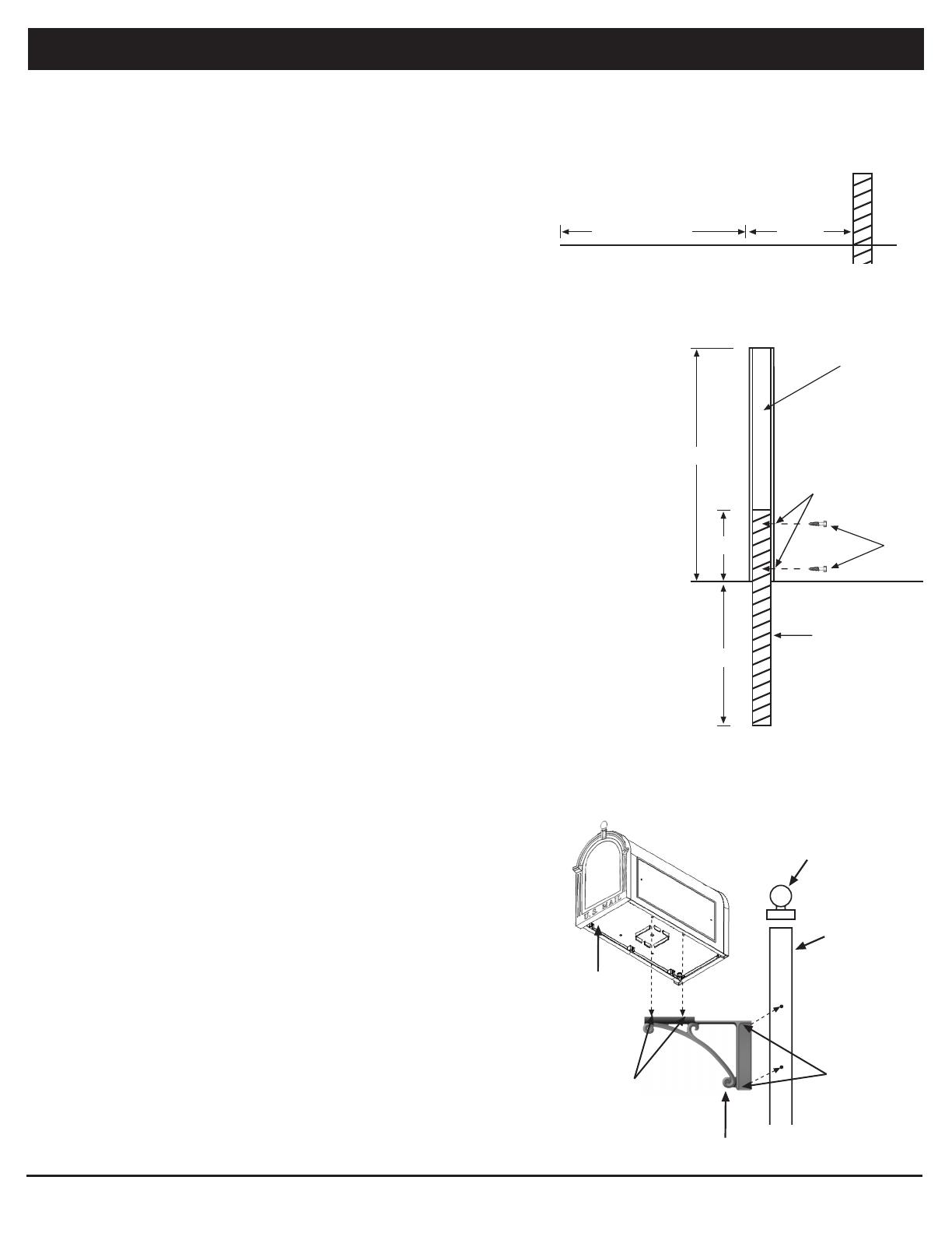
2) From post office recommended road setback line add 20.5” and mark position on ground for
front edge of post. (See Figure 1)
3) Place the 4”x 4” post into the hole so that the face of the post is at the marked line
(See step 2) leaving at least 18” out of the ground. (See Figure 2)
4) Partially backfill the hole around the post. Use a level make sure the post is vertical then complete
the back fill of the post hole packing the earth firmly. Recheck for vertical and adjust if necessary,
then repack soil. Note: For a more permanent installation you may use concrete mix to backfill the hole
unless it is against local post office or county road commission guidelines.
5) Carefully remove the aluminum post (B) from the plastic sleeve. To prevent a reaction between
the treated wood and aluminum, first slide the plastic sleeve over the partially buried 4x4 and
then slide the post down so that the two bolt holes are positioned away from the road and the
aluminum post is resting on the ground. (See Figure 2)
6) Plumb the aluminum post to vertical and use 2 – 1/4” x 2” lag bolts provided (C) to secure
aluminum post to treated post. (See Figure 2 - drilling pilot holes in the wood may be necessary )
Please Note: Apply small amount of Silicon Sealer (G) in and around holes before securing
the two bolts to the post.
7) Apply small amount of Silicon Sealer (G) in and around holes on brackets (D) and attach to
deluxe post (B) facing the street using 4 screws (E) provided. (See Figure 3)
DO NOT tighten screws until mailbox is attached. (if a double mailbox mount is being used, the road
set back will be recommended postal set back plus 9”, 2 sets of bracket are used and brackets are set parallel
with the street)
8) Place finial (F) over top of post (B) and, using a rubber mallet, tap finial
down firmly on the post.
Attaching your mailbox to the deluxe post and brackets:
1) Apply a small amount of Silicon Sealer (G) in and around the 4 holes on
top of the brackets (D). Place the mailbox (A) on top of the brackets (D)
with the back of the box against the post (B) and the box centered over the
brackets.
2) Using 4 screws (E) provided, reach inside the mailbox and place them thru
the 4 holes and into the bracket (threaded holes) hand tighten.
(Loosening the brackets on the post may be necessary to get alignment. If so
retighten the brackets to the post once the box is secure).
3) Use a Phillips screwdriver to tighten the 4 screws.
*
- The set screw and allen wrench are used to secure the finial to the post for
the Superior and Sorrento Post packages only.
MAILBOX DELUXE POST ASSEMBLY INSTRUCTIONS
GROUND LEVEL
18”
30”
54”
4” x 4” Post
(Not Provided)
B
C
Figure 2
20.5”
Recommended
Postal Setback
Figure 1
B
G
F
Figure 3
D
A
G
G
B
WP04-003 © 2004 WHITEHALL PRODUCTS Need Help? 1-800-728-2164 Visit our Web Site at: www.whitehallproducts.com AW-340 Rev. 6/10
A - Mailbox - 1 (Sold Separately)
B - 54” Deluxe Post - 1
C - 1/4” Lag Bolts - 2
D - Mounting Brackets - 2
E - 10/24 x 1/2” Panhead Screws - 8
F - Finial - 1
G - Tube of Silicon Sealer - 1
* - Set Screw - 1
* - Allen Wrench - 1


