Page is loading ...

Page 1 of 8
Installation and Operation Instructions
IMPORTANT! Read all instructions before installing and using. Installer: This manual must be delivered to the end user.
WARNING!
Failure to install or use this product according to manufacturer’s recommendations may result in property damage, serious injury, and/
or death to those you are seeking to protect!
Do not install and/or operate this safety product unless you have read and understood the safety information
contained in this manual.
1. Proper installation combined with operator training in the use, care, and maintenance of emergency warning devices are essential to
ensure the safety of emergency personnel and the public.
2. Emergency warning devices often require high electrical voltages and/or currents. Exercise caution when working with live electrical
connections.
3. This product must be properly grounded. Inadequate grounding and/or shorting of electrical connections can cause high current arcing,
which can cause personal injury and/or severe vehicle damage, including re.
4. Proper placement and installation is vital to the performance of this warning device. Install this product so that output performance of
the system is maximized and the controls are placed within convenient reach of the operator so that they can operate the system without
losing eye contact with the roadway.
5. Do not install this product or route any wires in the deployment area of an air bag. Equipment mounted or located in an air bag
deployment area may reduce the eectiveness of the air bag or become a projectile that could cause serious personal injury or death.
Refer to the vehicle owner’s manual for the air bag deployment area. It is the responsibility of the user/operator to determine a suitable
mounting location ensuring the safety of all passengers inside the vehicle particularly avoiding areas of potential head impact.
6. It is the responsibility of the vehicle operator to ensure daily that all features of this product work correctly. In use, the vehicle operator
should ensure the projection of the warning signal is not blocked by vehicle components (i.e., open trunks or compartment doors),
people, vehicles or other obstructions.
7. The use of this or any other warning device does not ensure all drivers can or will observe or react to an emergency warning signal.
Never take the right-of-way for granted. It is the vehicle operator’s responsibility to be sure they can proceed safely before entering an
intersection, drive against trac, respond at a high rate of speed, or walk on or around trac lanes.
8. This equipment is intended for use by authorized personnel only. The user is responsible for understanding and obeying all laws
regarding emergency warning devices. Therefore, the user should check all applicable city, state, and federal laws and regulations. The
manufacturer assumes no liability for any loss resulting from the use of this warning device.
Specications:
LED PriZm II Perimeter Lights
3x7 4x6 7x9
Size 1.5” x 4.75” x 9.0” (w/ bezel) 1.5” x 6.0” x 8.5” (w/ bezel) 1.5” x 9.0” x 11.0” (w/ bezel)
Weight 1.0 lbs 1.1 lbs 2.25 lbs
Operating Voltage 12 VDC
Peak Current Draw
2
1.3 (8 LEDs), 1.6 (12 LEDs) 3.8 (24 LEDs), 4.6 (36 LEDs)

Page 2 of 8
Installation and Mounting:
The use of this or any warning device does not ensure that all drivers can or will observe or react to an emergency warning signal.
Never take the right-of-way for granted. It is your responsibility to be sure you can proceed safely before entering an intersection,
driving against trac, responding at a high rate of speed, or walking on or around trac lanes.
The eectiveness of this warning device is highly dependent upon correct mounting and wiring. Read and follow the manufacturer’s
instructions before installing or using this device. The vehicle operator should insure daily that all features of the device operate correctly.
In use, the vehicle operator should insure the projection of the warning signal is not blocked by vehicle components (i.e.: open trunks or
compartment doors), people, vehicles, or other obstructions.
This equipment is intended for use by authorized personnel only. It is the user’s responsibility to understand and obey all laws regarding
emergency warning devices. The user should check all applicable city, state and federal laws and regulations.
Code 3, Inc., assumes no liability for any loss resulting from the use of this warning device. Proper installation is vital to the performance of
this warning device and the safe operation of the
emergency vehicle. It is important to recognize that the operator of the emergency vehicle is under psychological and physiological stress
caused by the emergency situation. The warning device should
be installed in such a manner as to: A) Not reduce the output performance of the system, B) Place the controls within convenient reach of the
operator so that he can operate the system without losing eye
contact with the roadway.
Emergency warning devices often require high electrical voltages and/or currents. Properly protect and use caution around live electrical
connections. Grounding or shorting of electrical connections can cause high current arcing, which can cause personal injury and/or severe
vehicle damage, including re.
PROPER INSTALLATION COMBINED WITH OPERATOR TRAINING IN THE PROPER USE OF EMERGENCY WARNING DEVICES IS ESSENTIAL
TO INSURE THE SAFETY OF EMERGENCY PERSONNEL AND THE PUBLIC.
Unpacking and Pre-installation:
Carefully remove the light head from its protective packaging. Inspect the unit for transit damage. Report any damage to the carrier and
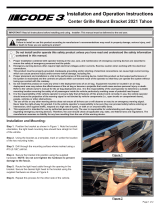
keep the shipping carton. Verify the contents of the package (refer to Table 3 and Figures 2 and 3). Test the lights before installation. To
test, touch the black wire to ground and the red wire to 12 VDC. If a problem occurs, contact the factory.
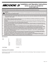
Step 1. Mark o and drill four ¼” diameter mounting holes and the 1” wire hole on the vehicles mounting surface using the dimensions
shown for the appropriate light (refer to Figures 4, 5 & 6). Verify free clearance exists behind the mounting surface for wires and fasteners
before drilling.
Step 2. Install customer supplied grommet in the 1” diameter wire hole. Install the four plastic grommets in the mounting holes (Code 3
supplied).
Step 3. Route the vehicle power wires and allow a minimum of 3” of slack to protrude from the center opening at each light head location.
Use 18 AWG for wires up to 40’ length, 16 AWG for wires up to 70’ length.
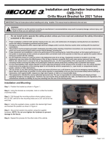
Step 4. Refer to the section “Device Operation” prior to nalizing the electrical connections. Prepare the vehicle power wires and the light
heads wires with terminations of the customer’s choice (not supplied) as follows: Red: +12 VDC, Black: Ground, White: Program, Purple:
Dim, Yellow: Sync, Green: Cuto (refer to Figure 1). Waterproof connectors are recommended.
Step 5. Route the power wires through the center opening of the light gasket or bezel and bezel gasket (refer to Figures 2 and 3). Connect
light head red (+12VDC) power wires and Black ground wires to the vehicle power system. Seal or cap the end of the white wire and other
unused wires to prevent inadvertent changes to the ash pattern or unexpected operation of the device.
Step 6. Verify proper light head operation by supplying electrical power to the system wires.
Step 7. Push the assembled electrical connectors through the center opening and into the vehicle.
Step 8. Install the lens gasket over the light head.
Step 9. Place the light head onto the light gasket or bezel and bezel gasket. The bezel and all gaskets are marked with the word “Top”. The
light head is not, but should be installed such that the wire harness is located directly across from the hole in the vehicle body.
Step 10. Install onto the light head the outer lens and secure to the vehicle using the four supplied #6 x 1 ¼” screws.

Page 3 of 8
Figure 1

Page 4 of 8
Device Operation:
Flash Pattern Selection - To select a dierent ash pattern, apply +12 VDC to the red wire and connect the black wire to the power supply
ground. Touching the white wire to power supply ground for less than 1 second will change to the next pattern, for 1-2 seconds will change
to the previous pattern, and over 2 seconds will reset to the default pattern (Pattern #1). During the programming process, the light head
will turn certain lights on to indicate if it will go to the next, previous, or default pattern upon release of the white wire, See Table 2 for details.
Cycle through the various patterns until the desired pattern is selected, Table 1 contains the available ash patterns. The unit will retain this
pattern even when power is removed. For units that are ashed with an external control system such as a multiplexer or a asher unit, the
heads should be set to steady burn. It is suggested that all heads be set to the desired pattern at a workbench prior to installation.
Flash Patterns
Pattern Solid Color Split Color
SAE J595 CA T13
Amber Blue Red White Amber Blue Red
1 CYCLE Ph1 CYCLE L/R N/C N/C N/C N/C N/C N/C N/C
2 80 FPM NFPA QUAD Ph1
80 FPM NFPA QUAD
L/R
Class 1/2* Class 1 Class 1 Class 1 Class E Class B Class B
3 STEADY STEADY N/C N/C N/C N/C N/C N/C N/C
4 75 FPM SINGLE Ph1 75 FPM SINGLE L/R Class 1/2* Class 1 Class 1 Class 1 Class E Class B Class B
5 150 FPM SINGLE Ph1 150 FPM SINGLE L/R Class 1/2* Class 1 Class 1 Class 1 N/C N/C N/C
6 250 FPM SINGLE Ph1 250 FPM SINGLE L/R N/C N/C N/C N/C N/C N/C N/C
7 75 FPM DOUBLE Ph1 75 FPM DOUBLE L/R Class 1/2* Class 1 Class 1 Class 1 Class E Class B Class B
8 150 FPM DOUBLE Ph1 150 FPM DOUBLE L/R Class 1/2* Class 1 Class 1 Class 1 N/C N/C N/C
9 75 FPM TRIPLE Ph1
75 FPM TRIPLE POP
L/R
Class 1/2* Class 1 Class 1 Class 1 Class E Class B Class B
10 150 FPM TRIPLE Ph1 150 FPM TRIPLE L/R Class 1/2* Class 1 Class 1 Class 1 N/C N/C N/C
11 75 FPM QUAD POP Ph1
75 FPM QUAD POP
L/R
Class 1/2* Class 1 Class 1 Class 1 Class E Class B Class B
12 150 FPM QUAD POP Ph1
150 FPM QUAD POP
L/R
Class 1/2* Class 1 Class 1 Class 1 N/C N/C N/C
13 70 FPM Five Ph1 70 FPM Five L/R Class 1/2* Class 1 Class 1 Class 1 Class E Class B Class B
14 150 FPM Five Ph1 150 FPM Five L/R Class 1/2* Class 1 Class 1 Class 1 N/C N/C N/C
15 MOD FLASH Ph1 MOD FLASH L/R N/C N/C N/C N/C N/C N/C N/C
16 CYCLE Ph2 CYCLE Solid N/C N/C N/C N/C N/C N/C N/C
17 80 FPM NFPA QUAD Ph2
80 FPM NFPA QUAD
Solid
Class 1/2* Class 1 Class 1 Class 1 Class E Class B Class B
18 STEADY STEADY N/C N/C N/C N/C N/C N/C N/C
19 75 FPM SINGLE Ph2 75 FPM SINGLE Solid Class 1/2* Class 1 Class 1 Class 1 Class E Class B Class B
20 150 FPM SINGLE Ph2 150 FPM SINGLE Solid Class 1/2* Class 1 Class 1 Class 1 N/C N/C N/C
21 250 FPM SINGLE Ph2 250 FPM SINGLE Solid N/C N/C N/C N/C N/C N/C N/C
22 75 FPM DOUBLE Ph2 75 FPM DOUBLE Solid Class 1/2* Class 1 Class 1 Class 1 Class E Class B Class B
23
150 FPM DOUBLE Ph2
150 FPM DOUBLE
Solid
Class 1/2* Class 1 Class 1 Class 1 N/C N/C N/C
24
75 FPM TRIPLE Ph2
75 FPM TRIPLE POP
Solid
Class 1/2* Class 1 Class 1 Class 1 Class E Class B Class B
25 150 FPM TRIPLE Ph2 150 FPM TRIPLE Solid Class 1/2* Class 1 Class 1 Class 1 N/C N/C N/C
26
75 FPM QUAD POP Ph2
75 FPM QUAD POP
Solid
Class 1/2* Class 1 Class 1 Class 1 Class E Class B Class B
27
150 FPM QUAD POP Ph2
150 FPM QUAD POP
Solid
Class 1/2* Class 1 Class 1 Class 1 N/C N/C N/C
28 70 FPM Five Ph2 70 FPM Five Solid Class 1/2* Class 1 Class 1 Class 1 Class E Class B Class B
29 150 FPM Five Ph2 150 FPM Five Solid Class 1/2* Class 1 Class 1 Class 1 N/C N/C N/C
30 MOD FLASH Ph2 MOD FLASH Solid N/C N/C N/C N/C N/C N/C N/C
* Solid Color Amber - Class 1, Split Color Amber - Class 2

Page 5 of 8
Pattern Change Indication
Light Head Next Pattern
Indication
Previous Pattern
Indication
Default Pattern
Indication
Solid Color (All sizes) No lights on All lights on All lights ash once
Split Color (All sizes) Right side on Left side on All lights ash twice
Flash Pattern Syncing - The ash patterns of multiple light heads may be synced together by simply connecting the yellow
wires of all light heads to be synced. Up to 20 light heads may be synced in this fashion. All ash patterns that share the
same ash rate may be synced together. For example, any 75 FPM ash pattern may be synced with any other 75 FPM ash
pattern, etc. If this feature is not desired, the end of the yellow wire must be sealed or capped.
Flash Pattern Dimming - Flash patterns are dimmed when the purple wire is given a +12VDC signal. It is up to the installer
to determine how to integrate this feature into their system. If this feature is not desired, the end of the purple wire must be
sealed or capped.
Cuto and Steady Burn Override - The green wire supports two dierent features, but only one may be used for a given
light head. The green wire’s default mode is Cuto. To toggle between the two modes, connect the black and white wires
to ground. Apply +12VDC to the red wire. The light head will ash once and remain o until the white wire is removed from
ground. This indicates that the mode has been successfully changed.
NOTE: These two features require a dierent signal to activate them. Cuto is activated by a ground signal, and
Steady Burn Override is activated by a +12VDC signal.
Cuto - Allows a ground input signal to the green wire to cut o the whole light on solid-color 3x7, 4x6 and 7x9 light heads, or
the right side of the light head on left/right spit color light heads. This is useful for NFPA vehicles that need to cut o their white
lights when blocking right-of-way. Upon removal of the ground signal, the current ash pattern will resume.
Replacement Parts:
3X7 4X6 7X9
LENS & LENS GASKET LENS & LENS GASKET LENS & LENS GASKET
CR0005 RED CR0014 RED CR0023 RED
CR0006 AMBER CR0015 AMBER CR0024 AMBER
CR0007 BLUE CR0016 BLUE CR0025 BLUE
CR0008 CLEAR CR0017 CLEAR CR0026 CLEAR
LENS LENS LENS
CR0009 RED CR0018 RED CR0027 RED
CR0010 AMBER CR0019 AMBER CR0028 AMBER
CR0011 BLUE CR0020 BLUE CR0029 BLUE
CR0012 CLEAR CR0021 CLEAR CR0030 CLEAR
LENS GASKET LENS GASKET LENS GASKET
CR0013 CR0022 CR0031
T07919 T07920 T07921
Maintenance:
The lens is eld removable for cleaning and replacement. Remove the lens by unscrewing the four mounting screws. Use mild detergent,
warm water and a soft cloth to clean both surfaces of the lens. Use of any other chemicals may void product warranty. Thoroughly dry before
reinstalling.

Page 6 of 8
Installation Dimensions:
Figure 2
Figure 3
Figure 4

Page 7 of 8
Notes:

Page 8 of 8
An ECCO SAFETY GROUP™ Brand
ECCOSAFETYGROUP.com
10986 North Warson Road, St. Louis, MO 63114 USA
Technical Service USA (314) 996-2800
CODE3ESG.com
Product Returns:
If a product must be returned for repair or replacement*, please contact our factory to obtain a Return Goods Authorization Number (RGA
number) before you ship the product to Code 3®, Inc. Write the RGA number clearly on the package near the mailing label. Be sure you use
sucient packing materials to avoid damage to the product being returned while in transit.
*Code 3®, Inc. reserves the right to repair or replace at its discretion. Code 3®, Inc. assumes no responsibility or liability for expenses incurred for the removal and /or reinstallation of products requiring
service and/or repair.; nor for the packaging, handling, and shipping: nor for the handling of products returned to sender after the service has been rendered.
Manufacturer Limited Warranty Policy:
Manufacturer warrants that on the date of purchase this product will conform to Manufacturer’s specications for this product (which are avail-
able from the Manufacturer upon request). This Limited Warranty extends for Sixty (60) months from the date of purchase.
DAMAGE TO PARTS OR PRODUCTS RESULTING FROM TAMPERING, ACCIDENT, ABUSE, MISUSE, NEGLIGENCE, UNAPPROVED MODIFICA-
TIONS, FIRE OR OTHER HAZARD; IMPROPER INSTALLATION OR OPERATION; OR NOT BEING MAINTAINED IN ACCORDANCE WITH THE
MAINTENANCE PROCEDURES SET FORTH IN MANUFACTURER’S INSTALLATION AND OPERATING INSTRUCTIONS VOIDS THIS LIMITED WAR-
RANTY.
Exclusion of Other Warranties:
MANUFACTURER MAKES NO OTHER WARRANTIES, EXPRESS OR IMPLIED. THE IMPLIED WARRANTIES FOR MERCHANTABILITY, QUALITY
OR FITNESS FOR A PARTICULAR PURPOSE, OR ARISING FROM A COURSE OF DEALING, USAGE OR TRADE PRACTICE ARE HEREBY EX-
CLUDED AND SHALL NOT APPLY TO THE PRODUCT AND ARE HEREBY DISCLAIMED, EXCEPT TO THE EXTENT PROHIBITED BY APPLICABLE
LAW. ORAL STATEMENTS OR REPRESENTATIONS ABOUT THE PRODUCT DO NOT CONSTITUTE WARRANTIES.
Remedies and Limitation of Liability:
MANUFACTURER’S SOLE LIABILITY AND BUYER’S EXCLUSIVE REMEDY IN CONTRACT, TORT (INCLUDING NEGLIGENCE), OR UNDER ANY
OTHER THEORY AGAINST MANUFACTURER REGARDING THE PRODUCT AND ITS USE SHALL BE, AT MANUFACTURER’S DISCRETION, THE
REPLACEMENT OR REPAIR OF THE PRODUCT, OR THE REFUND OF THE PURCHASE PRICE PAID BY BUYER FOR NON-CONFORMING PROD-
UCT. IN NO EVENT SHALL MANUFACTURER’S LIABILITY ARISING OUT OF THIS LIMITED WARRANTY OR ANY OTHER CLAIM RELATED TO
THE MANUFACTURER’S PRODUCTS EXCEED THE AMOUNT PAID FOR THE PRODUCT BY BUYER AT THE TIME OF THE ORIGINAL PURCHASE.
IN NO EVENT SHALL MANUFACTURER BE LIABLE FOR LOST PROFITS, THE COST OF SUBSTITUTE EQUIPMENT OR LABOR, PROPERTY
DAMAGE, OR OTHER SPECIAL, CONSEQUENTIAL, OR INCIDENTAL DAMAGES BASED UPON ANY CLAIM FOR BREACH OF CONTRACT, IM-
PROPER INSTALLATION, NEGLIGENCE, OR OTHER CLAIM, EVEN IF MANUFACTURER OR A MANUFACTURER’S REPRESENTATIVE HAS BEEN
ADVISED OF THE POSSIBILITY OF SUCH DAMAGES. MANUFACTURER SHALL HAVE NO FURTHER OBLIGATION OR LIABILITY WITH RESPECT
TO THE PRODUCT OR ITS SALE, OPERATION AND USE, AND MANUFACTURER NEITHER ASSUMES NOR AUTHORIZES THE ASSUMPTION OF
ANY OTHER OBLIGATION OR LIABILITY IN CONNECTION WITH SUCH PRODUCT.
This Limited Warranty denes specic legal rights. You may have other legal rights which vary from jurisdiction to jurisdiction. Some jurisdic-
tions do not allow the exclusion or limitation of incidental or consequential damages.
© 2016 Code 3, Inc. all rights reserved.
T55065 Rev. C
Warranty:
/