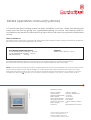
ComfortHeat MCD4 Operating instructions
- Category
- Thermostats
- Type
- Operating instructions

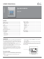
MCD4 operations manual (hydronic)
TECHNICAL DATA
Supply Voltage: 240Vac, 50/60hz
Output Relay: 16A SPST, 3600W max
Switching Differential: 0.4 degC
Built-in Switch: 2 pole 16A
Temperature Range: 0/+50 degC
Housing/protection: IP20 & IP21
Dimensions (HxWxD): 115mm x 84mm x 58mm
Sensor Length: 3m
Mounted: Vertically/Flush Mounted
Comfort Heat Australia Pty Ltd
www.comfortheat.com.au
p: 02 9979 8600 f: 02 9979 7706
MCD4
PRIOR TO TURNING ON
The sub-floor slab or screed has to be fully cured before turning the heating on.When turning on the floor for the first time,
increase the floor temperature gradually over 2-3 days.
WARRANTY
THERMOSTAT & SENSOR - 2 years
A Comfort Heat floor heating system has been installed in your floor. Under floor heating will
warm from the floor up giving you unparalleled feeling of comfort. This heating system is
controlled by an electronic thermostat that has a floor or air sensor for optimum temperature
control.
The MICROTEMP RANGE of electronic thermostats
are specifically designed for underfloor heating
systems.
The thermostats are vertically flush mounted and
have a 2pole isolator with 16A output relay.
MCD4 - The MCD4 thermostat has a built in programmable time-clock to automatically turn the floor heating system
ON and OFF at selected times with the addition of an air sensing option with floor limit mode or floor sensor only.
During the OFF periods the floor does not turn OFF but programs the floor temperature to your selected ‘set back
temperature’.When the appears on your screen, the floor is heating. If you see ‘E1’ or‘E2’ there is an error.
RECOMENDED TEMPERATURE SETTINGS
FLOOR TEMPERATURE [CERAMIC] - 28 degC
FLOOR TEMPERATURE [TIMBER] - 25 degC
AIR TEMPERATURE - 20 degC

1
© 2010 OJ Electronics A/S
Type MCC4/MCD4
English
67033 01/10 (DJU)
© 2010 OJ Electronics A/S
USER MANUAL
Contents
Introduction
The thermostat can switch on your heating system at predetermined
times on different days of the week. For each day of the week, you
can set individual temperatures for 4 different periods, called events.
Lowering the temperature when the home is unoccupied will reduce
your energy costs without reducing comfort.
The thermostat comes with a default schedule suitable for most
homes. Unless you change the settings, the thermostat will operate
in compliance with the default schedule.
Furthermore, the thermostat features an adaptive function that
automatically changes heating period start times so as to ensure
that the required temperature is reached at the set time. After three
days the adaptive function has learned when the heating must be
switched on.
First time settings
The fi rst time you switch the interrupter ON “I”, language, time and
date must be set. The menu will automatically guide you through the
process.
• Choose your language with the Up and Down buttons and
confi rm with OK.
• Set the actual hour and press the OK button. Then set the mi-
nutes. Press OK.
• Set the actual date: year, month and day. Confi rm the settings
with the OK button.
The thermostat is now ready for use and will control your heating
in accordance with the pre-programmed 4-event schedule, see
Factory settings.
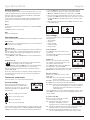
Navigation buttons
14:08
Comfort Menu Manual
Wed
20°C
Power interrupter
Introduction ................................................................................ 1
First time settings ...................................................................... 1
General operation ...................................................................... 2
Back......................................................................................... 2
Exit ........................................................................................... 2
Operation mode ......................................................................... 2
Auto mode .............................................................................. 2
Manual mode .......................................................................... 2
Comfort mode ......................................................................... 2
Thermostat setup menus .......................................................... 2
4-event settings ......................................................................... 2
User settings .............................................................................. 2
Time and date ......................................................................... 2
Child lock ................................................................................ 2
Display settings ...................................................................... 2
4-event schedule .................................................................... 2
Energy monitor ....................................................................... 3
Engineer settings ....................................................................... 3
Offset temperature................................................................... 3
Adaptive function..................................................................... 3
Application ............................................................................... 3
Temperature scale ................................................................... 3
Language ................................................................................. 3
Factory reset ............................................................................ 3
Information .............................................................................. 3
Back......................................................................................... 3
Exit ........................................................................................... 3
Error messages ......................................................................... 3
Factory settings ......................................................................... 3
Preset schedule ....................................................................... 3

2© 2010 OJ Electronics A/S
Type MCC4/MCD4 English
General operation
The interrupter button allows you to turn the thermostat on “I” and
off “0” by sliding the button up and down. When the thermostat is
switched off “0”, the relay disengages. All settings, including time
and date, will be remembered.
The thermostat is intuitively operated using the navigation buttons.
The function of each button is indicated above the button in the
display.
Back
In various parts of the menus and submenus you will fi nd the Back
menu item.
Use Back to return to the last step.
Exit
Returns to initial dispay.
Operation mode
The thermostat features three different modes of temperature control:
Auto mode
Select Auto if you want the temperature to be controlled automa-
tically via the 4-event schedule.
Manual mode
Select Manual to cancel the programmed 4-event schedule (e.g.
during holidays) and to set the required temperature manually. You
may, for example, want to adjust the temperature to 5°C for frost
protection while you are away.
• Press Manual, confi rm with OK and choose the required tempe-
rature.
Comfort mode
Select Comfort to set a temporary comfort temperature
(so-called party mode) for a single event.
• Press Comfort, confi rm with OK and choose the required tempe-
rature. Then enter the required duration of comfort mode.
After the set time has elapsed, the thermostat will automatically
revert to Auto mode.
Please note: Comfort mode is a temporary manual setting that will
be automatically cancelled by the next event in the programmed
4-event schedule.
Thermostat setup menus
The menu allows you to select the following options:
4-event settings
Allows you to have the temperature con-
trolled automatically in accordance with a
program of your own choice. You can select
temperature settings for four different events
during the day:
When you wake up in the morning
When you are away at work
When you come home
When you go to bed at night
The thermostat is pre-programmed with a 4-event schedule for easy
and economic heating control, see Preset schedule under Factory
settings. The schedule can be easily changed in the following way:
1. Press the OK button to activate the 4-event settings display.
2. Choose the days for which you want to change the settings,
Mon-Fri or Sat-Sun using the up or down button. Press OK.
3. Now select the time and temperature for each daily event in the
program. Press OK and set the start time for the event concerned.
Confi rm with OK. Set the temperature for this event and confi rm
with OK.
4. After setting the required events, select Exit in the menu to return
to the initial display.
Temp Time
OK OK
40.0°C 08:00
Max
5.0°C 06:00
Min
25°C 05:00
User settings
In the user settings menu you can change the
following items:
• Time and date
• Child lock
• Display settings
• 4-event schedule
• Energy monitor
Time and date
Press OK and set the actual time in hours
and minutes.
The date will then be displayed. Set the date
and confi rm with OK.
Child lock
Allows you to lock the thermostat settings,
e.g. in public or other places where you do
not want the settings changed.
Press OK and set the child lock to On using
the down button. Confi rm with OK.
The child lock can be unlocked by pressing both the Comfort and
Manual buttons simultaneously for 5 seconds.
Display settings
Allows you to select what is shown on the
initial display.
Time/day: Shows the actual time and day at
the top of the display.
Set temp.: Shows the current temperature setting.
Act. temp.: Shows the actual measured temperature.
Scr. saver: Switches off the display after 30 seconds if no button is
pressed. Any subsequent press of a button reactivates
the display. The thermostat remains on and runs the
selected program.
Press the OK button to select or deselect the display options. Then
select Exit in the menu to return to the initial display and view your
chosen settings.
4-event schedule
Allows you to choose the type of weekly
4-event schedule you require.
5:2 : Monday to Friday with 4 events and
Saturday to Sunday with 2 events.
Typically used if you work from Monday to Friday.
6:1 : Monday to Saturday with 4 events and Sunday with 2 events.
Typically used if you work from Monday to Saturday.
7:0 : Monday to Sunday with 4 individual events. Allows you to
choose individual programs for each of the 7 days of week.
OK
4-Event settings
OK
User settings
OK
Child lock
OK
Display settings
OK
4-Event schedule
OK
Time and date

3
© 2010 OJ Electronics A/S
Select the required 4-event schedule and confi rm with OK.
For instructions on programming the time and temperature for the
4-event schedule, see 4-event settings.
Energy monitor
Allows you to view energy consumption for
the past 2 days, 30 days or 365 days.
Press OK for the chosen period. The value
in per cent (%) shows the relative amount of
time the heating has been on. The following fi gure is the cost for the
selected period. To ensure correct calculation, check the settings for
currency, price per kWh and load.
Currency: Press OK and chose the required currency.
Confi rm with OK.
Cost/unit: Press OK and set the actual cost of electricity.
The cost must be entered per kWh. Press OK.
Load: Press OK and enter the connected heating power.
The value must be in watt (W). Press OK.
Leave the menu by pressing Exit.
Engineer settings
The Engineer settings menu contains the following options:
• Offset temperature
• Adaptive function
• Application
• Temperature scale
• Language
• Factory reset
• Information
Offset temperature
If the actual measured temperature does not
corresponding to the thermostat value, you
can adjust the thermostat by offsetting the
temperature.
Press OK and enter the value of the measu-
red temperature. Confi rm with OK.
Adaptive function
Ensures that the required temperature has
already been reached when you get up in the
morning or come home from work. After just
a few days, the adaptive function will have
automatically calculated when the heating must be turned on.
Press OK and set the function to On. Confi rm with OK.
Application
Set the type of regulation used.
There are 3 options:
Floor reg. : The thermostat regulates fl oor
temperature only. A fl oor sen-
sor must be connected.
Room reg. : The thermostat regulates room temperature only.
Room/limit : The thermostat regulates room temperature with min.
and max. limits for fl oor temperature. A fl oor sensor
must be connected.
Regulator : The thermostat functions as a simple regulator and no
sensors are used. The setting is a percentage.
Press OK and select the required application. Confi rm with OK.
Temperature scale
Allows you to set the temperature range
within which the thermostat can be set. It is
then only possible to set a temperature within
this range in auto, comfort and manual mode.
Type MCC4/MCD4 English
Press OK to highlight Min temperature. Use the up or down but-
ton to select the minimum permissible temperature. Press OK and
select the maximum permissible temperature. Confi rm the settings
with OK.
Language
Allows the language used on the display to
be changed.
Press OK and select the required language.
Confi rm with OK.
Factory reset
Allows factory settings to be restored. Your
personal settings will be lost, see Factory
settings.
Press OK and choose Reset in the menu.
Confi rm with OK.
Information
Displays the thermostat software version.
Back
In various parts of the menus and submenus you will fi nd the Back
menu item.
Use Back to return to the last step.
Exit
Returns to initial dispay.
Error messages
If a fault or error occurs, the thermostat will display an error code as
follows:
E0: Internal failure. The thermostat is defective. Replace thermostat.
E1: Internal sensor defective or short-circuited.
E2: External sensor defective or short-circuited.
E5: Internal overheating. Inspect the installation.
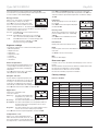
Factory settings
Preset schedule
Day 1-5
Event Time With fl oor sensor With room sensor
Day 06:00-08:00 25°C 20°C
Out 08:00-16:00 20°C 15°C
Home 16:00-22:30 25°C 21°C
Night 22:30-06:00 20°C 15°C
Day 6-7
Event Time With fl oor sensor With room sensor
Day 08:00-23:00 25°C 21°C
Night 23:00-08:00 20°C 15°C
OK
Factory reset
OK
Energy monitor
OK
Offset temp.
OK
Adaptive function
OK
Application
OK
Information
OK
Language
OK
Temp scale

INSTRUCTIONS
© 2010 OJ Electronics A/S · ® The OJ trademark is a registred trademark belonging to OJ Electronics A/S
67032 01/10 - (DJU)
Typ MCC4/MCD4
English
The thermostat is an electronic on/off thermo-
stat for temperature control by means of an
NTC sensor located either externally or inter-
nally within the thermostat.
The thermostat is for flush mounting in a wall
socket. A baseplate for external wall mounting
is available.
PRODUCT PROGRAMME
MCC4-1991-UA Clock-thermostat incl. floor
sensor.
MCC4-1999-UA Clock-thermostat with built-in
room sensor.
MCD4-1999-UA Clock-thermostat with 2 sen-
sors. Floor sensor and built-in
room sensor.
WARNING – Important Safety Instructions.
Disconnect the power supply before carrying
out any installation or maintenance work on this
control unit and associated components. This
control unit and associated components should
only be installed by a competent person (i.e. a
qualified electrician). Electrical installation must
be in accordance with appropriate statutory
regulations.
MOUNTING OF SENSOR
The floor sensor contains a safety extra-low
voltage (SELV) circuit, allowing it to be placed
as close to the floor surface as necessary with-
out having to take account of the risk of shock
should the sensor cable become damaged. The
two wires from the sensor to the mounting box,
must be additionally insulated, e.g. shrink flex.
To prevent loose cables from the fixed instal-
lation from coming into contact with the
terminal block for the floor sensor, they must be
restrained using cable ties.
It is recommended that the cable and sensor be
placed in a non-conductive installation pipe em-
bedded in the floor (fig. 3). The end of the pipe
must be sealed and the pipe placed as high as
possible in the concrete layer. Alternatively, the
sensor can be embedded directly in the floor.
The sensor cable must be led through a sepa-
rate pipe or segregated from power cables.
The floor sensor must be centred between the
heating cable.
The sensor cable may be extended up to 100
m by means of a separate two-core cable. Two
vacant wires in a multi-core cable used, for
example, to supply current to the floor heating
cable must not be used. The switching peaks of
such current supply lines may create interfer-
ence signals that prevent optimum controller
function. If a shielded cable is used, the shield
must not be connected to earth (PE). The two-
core cable must be placed in a separate pipe or
segregated from power cables.
MOUNTING OF THERMOSTAT
WITH BUILT-IN SENSOR
The room sensor is used for comfort tempera-
ture regulation in rooms. The thermostat should
be mounted on the wall approx. 1.6 m above
the floor in such a way as to allow free air circu-
lation around it. Draughts and direct sunlight or
other heat sources must be avoided (fig. 4). No
external sensor is connected.
Mounting of thermostat
1. Slide the power button down to Off “0”.
2. Release the front cover ONLY by inserting a
small screwdriver into the hole on either side
of the thermostat (fig. 1).
3. Connect the wires in accordance with the
diagram (fig. 2).
4. Mount the thermostat in the wall socket.
Please note that the adapter plate is properly
clipped on the thermostat.
5. Fit the frame and carefully press the cover
onto the thermostat. Ensure that both the
power slide button on the cover and the
power switch pin are down.
DO NOT open the thermostat by releasing the
four fixing clips on the back.
First time settings:
The first time the thermostat is connected, push
the power slide button to On “I”. Language,
time and date must be set using the buttons:
1. Set language
2. Set time
3. Set date
PROGRAMMING
See user manual.
FAULT LOCATION
If the sensor is disconnected or short-circuited,
the heating system is switched off. The sensor
can be checked against the resistance table
(fig. 5).
ERROR CODES
E0: Internal error. The thermostat must be
replaced.
E1: Built-in sensor short-circuited or
disconnected.
E2: External sensor short-circuited or
disconnected.
E5: Overheating, The temperature is too high in
the thermostat and switch off the heating.
CE MARKING
According to the following standard:
LVD/EMC: EN 60730-2-9
CLASSIFICATION
The product is a Class II device (enhanced
insulation) and must be connected to in the
following way:
Term. 1: Neutral (N
Term. 2: Phase (L) 230 V ±10%, 50/60 Hz
Term. 3–4: Load, max. 16 A / 3600 W
Term. X: Do not connect
Term. 5-6: External floor sensor
ENVIRONMENT AND RECYCLING
Please help us to protect the environment by
disposing of the packaging in accordance with
national regulations for waste processing.
RECYCLING OF OBSOLETE APPLIANCES
Appliances with this label must not
be disposed of with general
household waste. They must be
collected separately and disposed
of in compliance with local
regulations.
TECHNICAL DATA
Voltage ........................... 230 VAC ±10% 50 Hz
Max. pre-fuse .............................................. 16 A
Built-in circuit breaker .................... 2-pole, 16 A
Output relay ............ Make contact - SPST - NO
Output ................................ Max. 16 A / 3600 W
Control principle .................................... PWM/PI
Stand-by power ....................................... 0.6 W
Battery backup ...................................... 5 years
Temperature range .............................. +5/+40°C
Limit sensor (OCD4) ............................ +5/+40°C
Ambient operating temperature .......... +0/+25°C
Control pollution degree .................................. 2
Rated impulse voltage ................................ 4 kV
Enclosure rating ......................................... IP 21
Dimensions ..................... H/84, W/84, D/40 mm
Build-in depth ......................................... 20 mm
Display ....... 100x64 pixel STN - white backlight
EU Registered Design ........ 001101349-0001/2
The thermostat is maintenance free.
OJ ELECTRONICS A/S
Stenager 13B · DK-6400 Sønderborg
Tel: +45 73 12 13 14 · Fax: +45 73 12 13 13
[email protected] · www.oj.dk

© 2010 OJ Electronics A/S · ® The OJ trademark is a registred trademark belonging to OJ Electronics A/S
2
BR929A08
Sensor
Temp.(˚C) Value (ohm)
-10
0
10
20
30
64000
38000
23300
14800
9700
Fig. 2
Fig. 3
Fig. 5
Fig. 4
Fig. 1
-
 1
1
-
 2
2
-
 3
3
-
 4
4
-
 5
5
-
 6
6


ComfortHeat MCD4 Operating instructions
- Category
- Thermostats
- Type
- Operating instructions
Ask a question and I''ll find the answer in the document
Finding information in a document is now easier with AI
Other documents
-
OJ Electronics MCD4 User manual
-
OJ Electronics OCC4 User manual
-
-
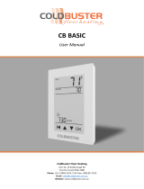 COLDBUSTER CB BASIC User manual
-
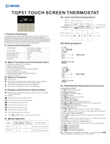 BEOK TGP51 User guide
-
 Celsiair UDG User manual
-
Roma Heating CT1000 User manual
-
-
 HeatMat NGT-567-0010 User manual
-


