Page is loading ...

FCL Series
Intelligent Stepper Motor
Linear Stages
User’s Manual

FCL Series Intelligent Stepper Motor Linear Stages
EDH0340En1032 — 04/19 ii
Warranty
Newport Corporation warrants this product to be free from defects in material and
workmanship for a period of 1 year from the date of shipment. If found to be defective
during the warranty period, the product will either be repaired or replaced at Newport’s
discretion.
To exercise this warranty, write or call your local Newport representative, or contact
Newport headquarters in Irvine, California. You will be given prompt assistance and
return instructions. Send the instrument, transportation prepaid, to the indicated service
facility. Repairs will be made and the instrument returned, transportation prepaid.
Repaired products are warranted for the balance of the original warranty period, or at
least 90 days.
Limitation of Warranty
This warranty does not apply to defects resulting from modification or misuse of any
product or part.
CAUTION
Warranty does not apply to damages resulting from:
• Incorrect usage:
- Driven load greater than maximum specified load.
- Stage speed higher than specified.
- Improper grounding.
¬ Connectors must be properly secured.
¬ When the load on the stage represents an electrical risk, it must be
connected to ground.
- Excessive or improper cantilever loads.
• Modification of the stage or any part thereof.
This warranty is in lieu of all other warranties, expressed or implied, including any
implied warranty of merchantability or fitness for a particular use. Newport Corporation
shall not be liable for any indirect, special, or consequential damages.
©2019 by Newport Corporation, Irvine, CA. All rights reserved.
Original instructions.
No part of this document may be reproduced or copied without the prior written
approval of Newport Corporation. This document is provided for information only, and
product specifications are subject to change without notice. Any change will be
reflected in future publishings.
CAUTION
Please return equipment in
the original (or equivalent)
packing.
Newport will not be
responsible for damage
incurred from inadequate
packaging if the original
packaging is not used.

FCL Series Intelligent Stepper Motor Linear Stages
iii EDH0340En1032 — 04/19
Table of Contents
Warranty ...........................................................................................................................ii
EC Declaration of Conformity .......................................................................................... v
Definitions and Symbols ................................................................................................. vi
Warnings.........................................................................................................................vii
Cautions ........................................................................................................................ viii
1.0 Introduction .................................................................................................. 1
2.0 System Overview........................................................................................... 2
2.1 General Description ........................................................................................................... 2
2.1.1 Package Contents ....................................................................................................... 2
2.1.2 Controller Specifications ........................................................................................... 3
2.1.3 Design Details ........................................................................................................... 3
2.1.4 Dimensions ................................................................................................................ 4
2.1.5 Weights ...................................................................................................................... 4
2.1.6 Assemblies ................................................................................................................. 5
2.1.7 FC-PS40 Power Supply ............................................................................................. 6
2.1.8 USB-RS422-1.8 USB Adapter .................................................................................. 6
2.1.9 FC-CB1 Daisy Chain Communication Cable ............................................................ 6
2.1.10 EQ120 Bracket ........................................................................................................ 7
2.2 Characteristics .................................................................................................................... 8
2.2.1 Definitions ................................................................................................................. 8
2.2.2 Mechanical Specifications ......................................................................................... 9
2.2.3 Load Characteristics and Stiffness ............................................................................. 9
2.3 System Environmental Specifications ................................................................................ 9
2.4 Connector Identification ................................................................................................... 10
2.5 Communication Settings .................................................................................................. 11
3.0 Getting Started ............................................................................................ 12
3.1 Mounting and Initial Setup ............................................................................................... 12
3.2 Connection ....................................................................................................................... 12
3.3 Initialization and Homing................................................................................................. 14
3.4 Daisy-Chaining ................................................................................................................ 15
3.5 Multi Stage Configuration ................................................................................................ 16
4.0 Programming .............................................................................................. 17
4.1 State Diagram ................................................................................................................... 17
4.2 Command Syntax ............................................................................................................. 19

FCL Series Intelligent Stepper Motor Linear Stages
EDH0340En1032 — 04/19 iv
4.3 Command Execution Time............................................................................................... 19
4.4 Command Set ................................................................................................................... 20
AC — Set/Get acceleration ............................................................................................ 22
BA — Set/Get backlash compensation ........................................................................... 23
BH — Set/Get hysteresis compensation ......................................................................... 24
FR — Set/Get stepper motor configuration .................................................................... 25
HT — Set/Get HOME search type ................................................................................. 26
ID — Set/Get stage identifier ......................................................................................... 27
JR — Set/Get jerk time ................................................................................................... 28
MM — Enter/Leave DISABLE state .............................................................................. 29
OH — Set/Get HOME search velocity ........................................................................... 30
OR — Execute HOME search ........................................................................................ 31
OT — Set/Get HOME search time-out ........................................................................... 32
PA — Move absolute ..................................................................................................... 33
PR — Move relative ....................................................................................................... 34
PT — Get motion time for a relative move .................................................................... 35
PW — Enter/Leave CONFIGURATION state ............................................................... 36
RS —Reset controller ..................................................................................................... 37
RS## — Reset controller’s address ................................................................................ 38
SA — Set/Get controller’s RS422 address ..................................................................... 39
SE — Configure/Execute simultaneous started move .................................................... 40
SL — Set/Get negative software limit ............................................................................ 41
SR — Set/Get positive software limit ............................................................................. 42
ST — Stop motion .......................................................................................................... 43
TB — Get command error string .................................................................................... 44
TE — Get last command error ........................................................................................ 45
TH — Get set-point position .......................................................................................... 46
TP — Get current position .............................................................................................. 47
TS — Get positioner error and controller state ............................................................... 48
VA — Set/Get velocity ................................................................................................... 50
VE — Get controller revision information ..................................................................... 51
ZT — Get all configuration parameters .......................................................................... 52
5.0 Maintenance ................................................................................................ 53
5.1 Maintenance ..................................................................................................................... 53
5.2 Repair ............................................................................................................................... 53
5.3 Troubleshooting ............................................................................................................... 54
Service Form ........................................................................................................ 55

FCL Series Intelligent Stepper Motor Linear Stages
v EDH0340En1032 — 04/19
EC Declaration of Conformity

FCL Series Intelligent Stepper Motor Linear Stages
EDH0340En1032 — 04/19 vi
Definitions and Symbols
The following terms and symbols are used in this documentation and also appear on the
product where safety-related issues occur.
General Warning or Caution
The exclamation symbol may appear in warning and caution tables in this document.
This symbol designates an area where personal injury or damage to the equipment is
possible.
The following are definitions of the Warnings, Cautions and Notes that may be used in
this manual to call attention to important information regarding personal safety, safety
and preservation of the equipment, or important tips.
WARNING
Warning indicates a potentially dangerous situation which can result
in bodily harm or death.
CAUTION
Caution indicates a potentially hazardous situation which can result
in damage to product or equipment.
NOTE
Note indicates additional information that must be considered by the user or
operator.
European Union CE Mark
The presence of the CE Mark on Newport Corporation equipment means that it has
been designed, tested and certified as complying with all applicable European Union
(CE) regulations and recommendations.
Warnings and Cautions
ATTENTION
This stage is a Class A device. In a residential environment, this
device can cause electromagnetic interference. In this case, suitable
measures must be taken by the user.

FCL Series Intelligent Stepper Motor Linear Stages
vii EDH0340En1032 — 04/19
Warnings
WARNING
The translation of objects of all types carries potential risks for operators. Ensure
the protection of operators by prohibiting access to the dangerous area and by
informing the personnel of the potential risks involved.
WARNING
Do not use this stage when its motor is emitting smoke or is unusually hot to the
touch or is emitting any unusual odor or noise or is in any other abnormal state.
Stop using the stage immediately, switch off the motor power by disconnecting the
power supply.
After checking that smoke is no longer being emitted contact your Newport service
facility and request repairs. Never attempt to repair the stage yourself as this can
be dangerous.
WARNING
Make sure that this stage is not exposed to moisture and that liquid does not get
into the stage.
Nevertheless, if any liquid has entered the stage, switch off the motor power by
disconnecting the power supply.
Contact your Newport service facility and request repairs.
WARNING
Do not insert or drop objects into this stage, this may cause an electric shock, or
lock the drive.
Do not use this stage if any foreign objects have entered the stage. Switch off the
motor power by disconnecting the power supply.
Contact your Newport service facility for repairs.
WARNING
Do not place this stage in unstable locations such as on a wobbly table or sloping
surface, where it may fall or tip over and cause injury.
If this stage has been dropped or the case has been damaged, switch off the motor
power by disconnecting the power supply.
Contact your Newport service facility and request repairs.
WARNING
Do not attempt to modify this stage; this may cause an electric shock or downgrade
its performance.
WARNING
Do not exceed the usable depth indicated for the mounting holes (see section
“Dimensions”). Longer screws can damage the mechanics or cause a short-circuit.

FCL Series Intelligent Stepper Motor Linear Stages
EDH0340En1032 — 04/19 viii
Cautions
CAUTION
Do not place this stage in a hostile environment such as X-Rays, hard UV,… or in
any vacuum environment.
CAUTION
Do not place this stage in a location affected by dust, oil fumes, steam or high
humidity. This may cause an electric shock.
CAUTION
Do not leave this stage in places subject to extremely high temperatures or low
temperatures. This may cause an electric shock.
• Operating temperature: +10 to +35 °C.
• Storage temperature: -10 to +40 °C (in its original packaging).
CAUTION
Do not move this stage if its motor power is on.
Make sure that cables are disconnected before moving the stage. Failure to do so
may damage the cable and cause an electrical shock.
CAUTION
Be careful that the stage is not bumped when it is being carried. This may cause it
to malfunction.
CAUTION
When handling this stage, always unplug the equipment from the power source for
safety.
CAUTION
Contact your Newport service facility to request cleaning and specification control
every year.

FCL Series Intelligent Stepper Motor Linear Stages
1 EDH0340En1032 — 04/19
1.0 Introduction
This manual provides operating instructions for the intelligent stepper motor linear stage
that you have purchased:
• FCL50
• FCL100
• FCL200
The FCL is a precision linear stage with an integrated stepper motor/controller. The
stage can be easily controlled from a PC, using a downloadable graphical user interface
(GUI). Communication with the FCL is achieved via an RS-422 serial link. A USB to
RS422 adaptor can be used (requires Windows™ XP or Windows™ 7 operating
system). While the GUI enables basic motion, advanced application programs can be
developed via an ASCII command interface and a set of two letter mnemonic
commands.
FCL Series linear stages: 50, 100, 200 mm travels.
Intelligent Stepper Motor
Linear Stages
FCL Series

FCL Series Intelligent Stepper Motor Linear Stages
EDH0340En1032 — 04/19 2
2.0 System Overview
2.1 General Description
The FCL linear stage line is an evolution of the industry proven ILS stage. Building on
the robust construction of recirculating ball technology in the guide and screw, the ILS
was value engineered, keeping only the features necessary for everyday precision
positioning needs. This and the addition of an integrated stepper motor/controller makes
the FCL the ultimate choice in user-friendly precision stages.
The FCL line incorporates similar stepper controller technology found in the popular
SMC and ESP301 controllers and extended this further by integrating the electronics
into the stepper motor housing, resulting in the Newport-proprietary iPP intelligent
stepper motor. Similar to the successful CONEX concept for DC motors, iPP
technology completely eliminates controller or driver set up. Just connect power and
communication and install the GUI. Up to 4 FC series units can be daisy-chained and
controlled by a single GUI, via USB (USB-RS422-1.8) and direct RS-422 (daisy
chaining cable FC-CB1).
2.1.1 Package Contents
• FCLxxx Intelligent Stepper Motor Linear Stage, 50, 100 or 200 mm
• Stage test report
The following parts are to be ordered separately
• FC-PS40 FC Stage Power Supply (Cable Length: 1.75 m)
• USB-RS422-1.8 USB Adapter (Cable Length: 1.8 m)
• FC-CB1 Daisy Chain Communication Cable (Cable Length: 1 m)

FCL Series Intelligent Stepper Motor Linear Stages
3 EDH0340En1032 — 04/19
2.1.2 Controller Specifications
General description Single Axis Intelligent Stepper Motor
Control capability Stepper motors, open loop
Output power 24 VDC peak, 2.5 A peak PWM amplifier
Control loop – PI control of motor phase current with programmable
idle state
– 2 kHz servo rate
– Backlash compensation
Motion Point-to-point motion with S-gamma profile and jerk time
control.
Computer interface USB +5 V (USB): <0.5 A, Windows Compatible
Programming – 40+ intuitive, 2-letter ASCII commands
– Command set includes software limits, user units,
synchronized motion start, stop all…
Communication rate 115 200 baud (serial link over USB)
Internal safety features End of range checks, power limit checks, watchdog timer
Consumption +24 V (FC-PS40): <1.67 A
2.1.3 Design Details
Base Material Aluminum
Motor Integrated iPP 2-phase step motor and controller/driver
Drive Mechanism Backlash-free ball screw
Drive Screw Pitch (mm) 2
Bearings Recirculating ball bearings
Limit Switches Optical
Origin Optical at center of travel
Communication RS422, USB
Cable Cables and power supply sold separately

FCL Series Intelligent Stepper Motor Linear Stages
EDH0340En1032 — 04/19 4
2.1.4 Dimensions
2.1.5 Weights
Weight [lb (kg)]
FCL50 7.28 (3.3)
FCL100 7.94 (3.6)
FCL200 9.02 (4.1)

FCL Series Intelligent Stepper Motor Linear Stages
5 EDH0340En1032 — 04/19
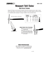
2.1.6 Assemblies
Below are a few assembly examples with FC linear and rotation stages. The FC series
mounting interfaces use common hole patterns, eliminating the need for adapter plates.
Call for compatibility with other Newport stages.
FCL200 and FCR100 rotation stage.
2 FCL stages in XY configuration and one FCR100 rotation stage.
2 FCL stages in XZ configuration with an EQ120 bracket.

FCL Series Intelligent Stepper Motor Linear Stages
EDH0340En1032 — 04/19 6
2.1.7 FC-PS40 Power Supply
NOTE
Each FC series stage requires a FC-PS40 power supply.
Box Dim. (L x D x H) 125 x 50 x 32 mm
Specifications
AC Input 100–240 VAC, 50–60 Hz, 1 A
DC Output 24 V, 1.67 A, 40 W max.
Cable Length 1.75 m between the power supply box and the iPP driver
board connector
2.1.8 USB-RS422-1.8 USB Adapter
Cable Length 1.8 m
2.1.9 FC-CB1 Daisy Chain Communication Cable
Cable Length 1 m

FCL Series Intelligent Stepper Motor Linear Stages
7 EDH0340En1032 — 04/19
2.1.10 EQ120 Bracket

FCL Series Intelligent Stepper Motor Linear Stages
EDH0340En1032 — 04/19 8
2.2 Characteristics
2.2.1 Definitions
Specifications of our products are established in reference to ISO 230 standard part II
“Determination of accuracy and repeatability of positioning numerically controlled
axes”.
This standard gives the definition of position uncertainty which depends on the 3
following parameters:
(Absolute) Accuracy
Difference between ideal position and real position.
On-Axis Accuracy
Difference between ideal position and real position after the compensation of linear
errors.
Linear errors include: cosine errors, inaccuracy of screw or linear scale pitch, angular
deviation at the measuring point (Abbe error) and thermal expansion effects. All
Newport motion electronics can compensate for linear errors.
The relation between absolute accuracy and on-axis accuracy is as follows:
Absolute Accuracy = On-Axis Accuracy + Correction Factor x Travel
Repeatability
Ability of a system to achieve a commanded position over many attempts.
Reversal Value (Hysteresis)
Difference between actual position values obtained for a given target position when
approached from opposite directions.
Minimum Incremental Motion (MIM or Sensitivity)
The smallest increment of motion a device is capable of delivering consistently and
reliably.
Resolution
The smallest increment that a motion device can theoretically move and/or detect.
Resolution is not achievable, whereas MIM, is the real output of a motion system.
The testing of on-axis accuracy, repeatability, and reversal error are made
systematically with test equipment in a controlled room (20 ±1 °C).
The test consists of 4 cycles in each direction, with 21 data points over the travel
resulting in a total 164 data points.
Guaranteed Specifications
Guaranteed maximum performance values are verified per Newport's A167 metrology
test procedure. For more information, please consult the metrology tutorial section in
the Newport catalog or at www.newport.com.

FCL Series Intelligent Stepper Motor Linear Stages
9 EDH0340En1032 — 04/19
2.2.2 Mechanical Specifications
FCL50 FCL100 FCL200
Travel Range (mm) 50 100 200
Minimum Incremental Motion (µm) 0.15
Uni-directional Repeatability (µm) 1.5 2 2
Bi-directional Repeatability
(1)
(µm) 4.5 or ±2.25 5 or ±2.5 5 or ±2.5
On-Axis Accuracy
(1)
(µm) 4 or ±2 5 or ±2.5 10 or ±5
Maximum Speed (mm/s) 20
Pitch
(1)
, αy (µrad) 50 or ±25 100 or ±50 200 or ±100
Yaw
(1)
, αz (µrad) 70 or ±35 100 or ±50 160 or ±80
MTBF (h) 20,000 with a 1 kg load at 50% duty cycle
1) Shown are peak to peak, guaranteed specifications or ± half the value as sometimes
shown. The typical specifications are about 2X better than the guaranteed values.
WARNING
To achieve the guaranteed specifications stated, stages must be fixed to a plane
surface with a flatness of 5 μ
m or better.
2.2.3 Load Characteristics and Stiffness
Cz, Normal center load capacity on bearings 250 N
Cx, Axial load capacity 40 N
kαx, Angular stiffness (Roll) 15 µrad/Nm
kαy, Angular stiffness (Pitch) 10 µrad/Nm
kαz, Angular stiffness (Yaw) 10 µrad/Nm
Q, Off-center load Q ≤ Cz/(1 + D/60)
D, Cantilever distance in mm
2.3 System Environmental Specifications
Operating temperature 5 °C to 40 °C
Operating humidity 20% to 85% relative humidity, non-condensing
Location Indoor use only

FCL Series Intelligent Stepper Motor Linear Stages
EDH0340En1032 — 04/19 10
2.4 Connector Identification
Each FC series stage includes two RS422 communication connectors and a 24 V DC
input connector. RS422 connector is connected to either PC (with USB-RS422-1.8
cable) or to RS422 connector of another FC series stage (by FC-CB1). Two RS422
connectors are interchangeable: either of the two connectors can be used for PC
connection or the input/output for daisy-chaining connection.
RS422 (2) 6-Pin RS422 communication connectors (connect to
USB-RS422-1.8 or to FC-CB1 cable)
24 V in 3-Pin JST PAP-03V-S (connect to FC-PS40)
Cable retainer 2 x M3 threaded hole to attach cable retainer

FCL Series Intelligent Stepper Motor Linear Stages
11 EDH0340En1032 — 04/19
2.5 Communication Settings
Communication parameters are preset in the FCL controller and do not require any
configuration:
Bits per second 115 200
Data bits 8
Parity None
Stop bits 1
Flow control None
End of line terminator C
R
L
F
• Communication standard: RS-422 4-wire full duplex without handshaking.
• 120 Ω termination resistor on receiver channel.

FCL Series Intelligent Stepper Motor Linear Stages
EDH0340En1032 — 04/19 12
3.0 Getting Started
3.1 Mounting and Initial Setup
To achieve the guaranteed specifications, stages must be fixed on a plane surface with a
flatness of 5 μm.
WARNING
The FC series, via threaded hole (M4), must be grounded to avoid electrical
disturbances generated by ground loops.
3.2 Connection
WARNING
Do not connect or disconnect cables to FC series stage while power is applied.
Follow the steps described below for the cable connections:
Remove the cover from integrated motor/controller housing by loosening the two
screws.
Refer to the Chapter 2.1 and Chapter 2.4 for the description of cables and connectors.
/