Extron SB 33 A 46-55 User manual

Category
Musical Equipment
Type
User manual

This manual is also suitable for

1
IMPORTANT:
Go to www.extron.com for the complete
user guide, installation instructions, and
specifications before connecting the
product to the power source.
SB 33 A Series • Setup Guide
Product Description
The SB 33 A speaker is an under-the-display powered soundbar speaker for use in small-to-medium conference rooms. It
features two 3" full range speaker drivers driven by an internal amplier module. The SB 33 A accepts analog and unbalanced
stereo input signals. Three individually buffered inputs are available so three separate sources can be connected without altering
performance.
The SB 33 A speaker enclosure is adjustable to match the width of the display and is mounted under the display. It features
an adjustable shelf to accommodate the mounting of a web cam or small conferencing camera. The SB 33 A is offered in four
different sizes to accommodate screen sizes from 46" to 80", as shown in the table below.
Installation Overview
The installation of the SB 33 A speaker uses the included wallplate to mark the wall where the SB 33 A is being mounted. After
the wallplate is attached to the wall the SB 33 A is then attached to the wallplate. The following section describes the mounting
procedure for safely and securely mounting the speaker.
NOTE: Install the wallplate onto wall material using common installation methods with applicable hardware dictated per
local building code.
Option Fit Display Size (diagonal) Fit Display Width Speaker Module Width
SB 33 A 46-55 46" — 55" 40" — 49" (101.6 cm — 124.5 cm) 16.25" (41.3 cm)
SB 33 A 55-65 55" — 65" 48" — 57" (121.9 cm — 144.8 cm) 20.25" (51.4 cm)
SB 33 A 65-70 65" — 70" 56" — 65" (142.2 cm — 165.1 cm) 24.25" (61.6 cm)
SB 33 A 75-80 75" — 80" 64" — 73" (162.6 cm — 185.4 cm) 28.25" (71.8 cm)
40"- 49"
SB 33 A 46-55
48"- 57"
SB 33 A 55-65
56"- 65"
SB 33 A 65-70
64"- 73"
SB 33 A 75-80
2
SB 33 A Series • Setup Guide (Continued)
Preparing the Mounting Location
Display
Left Speaker ModuleCenter
Bracket
Right Speaker Module
NOTE: Observe all applicable building codes and local ordinances when installing the SB 33 A speaker.
Before starting the installation, remove the center section assembly from the packaging and do the following:
Screws (2)
Grille
Center Section Cover
Lock Washers (2)
Center Bracket
Screws (2)
Web Camera
Mount
Grille Hoo
k
1. Remove the front grille from the center section cover using a grille hook.
2. Remove the center section cover from the center bracket standoffs by removing the two screws.
3. Remove the web camera mount from the center bracket (if necessary) by removing the two screws and lock washers that
attach it to the center bracket.
Installing the Wallplate on a Non-masonry Wall
NOTE: When attaching the wallplate to masonry, see Installing the wallplate on a masonry wall on page 4.
1. Mark the locations of the wall studs through the top vertical slots and bottom horizontal slots where four screws (not
included) will secure the SB 33 A speaker wallplate to the wall. Position and level the included wallplate (shown on the next
page) under the display screen (see the illustration above at the top of the page).
NOTES:
If the wallplate cannot be attached to two studs, the wallplate can be offset such that one side of the wallplate can
be attached to one stud and the other end of the wallplate can be attached to the wall using two (not included)
1/4" Kap Toggles. If the stud must come down the middle of the wallplate, secure the wallplate to the stud using
two screws and to the wall using two (not included) 1/4" Kap Toggles (one on the leftmost top slot and one on the
rightmost top slot)
The center of the wallplate does not need to be precisely aligned with the center of the display above it because the
speaker module on either end of the wallplate can be adjusted on the wallplate.
3
NOTE: Assuming that the display screen is level, allow for some space between the bottom of the display screen and
the top of the speaker because the speaker assemblies and the center bracket attach to the wallplate by hooking the
top mounting clasps of the speaker assemblies and center bracket over the top mounting rail of the wall plate.
To allow sufficient clearance between the top of the SB 33 A and the display screen above it, allow for at least a
minimum clearance of 11/16 inches (17.5 mm) between the highest part of the top rail of the wallplate and the top of
the speaker, as shown below. The display screen should not encroach into this area above the top rail.
INPUTS
POWER
MAX
12V
0.7A
OUTPUT
REMOTE
V
L
L
R
LEVEL BASS TREBLE
R
CG
10V 50mA
CLASS 2 WIRING
L SPEAKER
Wallplate
Side View
11/16"
(17.5 mm)
Wall
Minimum clearance between top of wallplate
and bottom of display is 11/16" (17.5 mm).
2. If necessary, cut a hole in the wall to route cables to the SB 33 A speaker.
3. Drill four pilot holes through the marked locations on the wall.
4. Screw the wallplate to the wall studs using four #14 x 1 3/4" self-tapping wood or metal screws and four 1/4" SAE washers
into the pilot holes.
NOTE: Use wood or metal screws depending on whether the studs are wood or metal.
Wall Stud
Wallplate
1/4" SAE Washer (x4)
#14 x 1 3/4" Self-tapping
Metal or Wood Screws (x4)
4
SB 33 A Series • Setup Guide (Continued)
Installing the Wallplate on a Masonry Wall
Mount the wallplate on a brick, stone, or concrete wall by doing the following:
1. Follow steps 1 and 2 of “Installing the wallplate on a non-masonry wall” starting on page 2.
NOTE: Because masonry installation does not involve wall studs, position the wallplate so that the mounting holes will
evenly distribute the weight of the SB 33 A.
2. Using a masonry drill bit, drill four pilot holes in the masonry wall at the locations you marked in step one.
NOTE: If you drill the pilot hole too shallow, the screw head might break off while it is being fastened into the hole.
Mounting Holes
Mounting Holes
Wallplate
NOTE: The center of the wallplate does not need to be precisely aligned with the center of the display above it because
the speaker module on either end of the wallplate can be adjusted on the wallplate.
3. For each pilot mounting hole:
a. Insert a 1/4" x 1 3/4" masonry screw through a 1/4" SAE washer.
b. Position the wallplate over the pilot holes
c. Insert each screw and washer through the wallplate and into the pilot hole.
Wallplate
1/4" SAE Washer (x4)
1/4" x 1 3/4"
Masonry Screws (x4)
d. Securely tighten the four screws to the wallplate.
5
Attaching the SB 33 A to the Wallplate
ATTENTION:
When attaching either speaker assembly or the center section to the wallplate, avoid damaging or scratching the
speaker assembly and center section cover.
Lorsque vous xez les enceintes ou la section centrale à la plaque murale, prenez garde à ne pas endommager ni
à rayer les enceintes et le couvercle de la section centrale.
1. Hook the top clasp edge of the left speaker assembly over the top rail (
1
) of the wallplate and slide it to left end of the
wallplate (
2
) so that the left end of the speaker assembly is aligned with the left end of the display.
Wallplate
Screws (2)
Left Speaker
11
3
3
DISPLAY
Left Speaker
Wallplate
Side View Side ViewFront View
Wall Wall
22
Tighten the two set screws on (
3
) the bottom of the left speaker assembly to the bottom rail of the wallplate.
2. Hook the top clasp edge of the right speaker assembly over the top rail (
1
) of the wallplate and slide it to right end of the
wallplate (
2
) so that the right end of the speaker assembly is aligned with the right end of the display.
INPUTS
POWER
MAX
12V
0.7A
OUTPUT
REMOTE
V
L
L
R
LEVEL BASS TREBLE
R
CG
10V 50mA
CLASS 2 WIRING
L SPEAKER
INPUTS
POWER
MAX
12V
0.
7A
OUTPUT
REMOTE
V
L
L
R
LEVEL
BASS TREBLE
R
C G
10V 50mA
CLASS 2 WIRING
L SPEAKER
Side View Side ViewFront View
Screws (2
)
33
Right Speaker
Wallplate
22
DISPLAY
Wall
Wall
Wallplate
Right Speaker
11
Tighten the two set screws (
3
) on the bottom of the right speaker assembly to the bottom rail of the wallplate.
3. Route the supplied power cable from the power supply in the left speaker enclosure to the power input connector of the
amplier in the right speaker enclosure.
INPUTS
POWER
MAX
12V
0.7A
OUTPUT
REMOTE
V
L
L
R
LEVEL BASSTREBLE
R
CG
10V 50mA
CLASS 2 WIRING
L SPEAKER
POWER
12V
0.7A MAX
Left Speaker Module
Power Supply
Right Speaker Module
Amplifier
DC Power
Input
DC Power Cord
Captive Screw
Connectors
Tie
Wraps
DC Power
Outputs
6
SB 33 A Series • Setup Guide (Continued)
ATTENTION:
Always use a power supply supplied by or specied by Extron. Use of an unauthorized power supply voids all
regulatory compliance certication and may cause damage to the supply and the end product.
L’utilisation d’une source d’alimentation non autorisée annule toute certication de conformité réglementaire, et peut
endommager la source d’alimentation et l’unité.
The installation shall be in accordance with the applicable provisions of National Electrical Code ANSI/NFPA 70,
article 725 and the Canadian Electrical Code part1, section 16.
Cette installation doit toujours être conforme aux dispositions applicables du Code américain de l’électricité
(National Electrical Code) ANSI/NFPA 70, article 725, et du Code canadien de l’électricité, partie 1, section 16.
The length of the exposed wires in the stripping process is critical. The ideal length is 3/16 inches (5 mm). Any
longer and the exposed wires may touch, causing a short circuit between them. Any shorter and the wires can be
easily pulled out even if tightly fastened by the captive screws.
La longueur des câbles exposés est primordiale lorsque l’on entreprend de les dénuder. La longueur idéale est de
5 mm (3/16 inches). S’ils sont trop longs, les câbles exposés pourraient se toucher et provoquer un court-circuit.
S’ils sont trop courts, ils peuvent être tirés facilement, même s’ils sont correctement serrés par les borniers à vis.
NOTE: Do not tin the wires. Tinned wire does not hold its shape and can become loose over time.
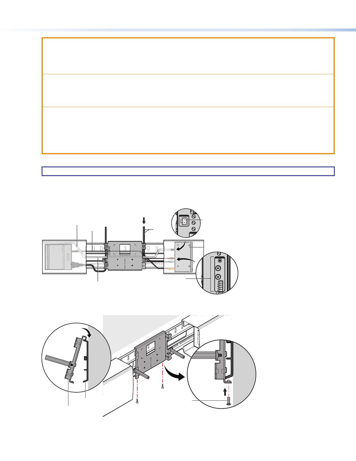
4. Route the supplied speaker cable from the left speaker module to the left speaker output of the amplifier (
2
), as shown
below.
INPUTS
OUTPUT
V
LEVEL BASS TREBLE
C
10V 5
CLASS 2 WIRING
L SPEAKER
INPUTS
WER
MAX
L
L
R
LEVEL
R
Right Speaker Amplifier
Side View
Front View
Amplifier
Audio Input
Connectors
Audio
Cable
Speaker Cable
Left Speaker Cable
Output
Display
Speaker Cable
Power Cable
22
1
1
5. Hook the top clasp edge of the center bracket over the top rail (
1
) of the wallplate and slide it to center of the display.
Screws (2)
22
11
Wallplate
Center Bracket
Side View
Side View
Wall
Wall
Tighten the two set screws (
2
) on the bottom of the center bracket to the bottom rail of the wallplate.
7
Attaching Power and Audio Sources to the SB 33 A
The SB 33 A has a power supply for the amplier housed in the left speaker enclosure. The power supply has an AC power input
connector (
A
) and a DC power output connector (
B
) that routes power to the amplier. See the illustration below.
Left Speaker/Power Supply
(Side View)
AABB
This section describes how the power and audio sources are attached to the SB 33 A, as shown in the following steps.
NOTE: Speaker and DC power cables must be routed before attaching the center bracket to the wallplate. See the previous
section.
e
e
Amplifier Module (inside Right Speaker module)
Power Cord
Front View
DC Power Cable
Power Supply
Left Speaker Module Wires
Audio Input Cable
1
Figure 1. Speaker and DC power cable routing
1. Wiring access points for the power and speaker cables to the SB 33 A are shown below.
Top Cable Access Points Bottom Cable Access Point Back Cable Access Points
Wallplate
Access Points
8
SB 33 A Series • Setup Guide (Continued)
Cables can be be secured with zip ties to cable tie off points located on the center bracket, as shown below.
e
e
Front View
Cable Tie-off Point
Zip Tie
2. Route the audio cable from the display to the audio input connectors of the power amplier (
1
) in the right speaker
assembly. See the cable access points illustration in step 1.
INPUTS
WER
MAX
L
L
R
LEVEL
R
Right Speaker Amplifier
Side View
Front View
Amplifier
Audio Input
Connectors
Audio
Cable
Speaker Cable
Display
Speaker Cable
Power Cable
11
3. Connect the power cord to the power supply in the left speaker assembly (
1
), as shown below.
e
e
Level, Bass,
Treble
Potentiometers
22
INPUTS
OUTPUT
V
LEVEL BASS TREBLE
C
10V 5
CLASS 2 WIRING
L SPEAKER
Amplifier Module (inside Right Speaker module)
Power Cord
Front View
DC Power Cable
Power Supply
Left Speaker Module Wires
Audio Input Cable
1
4. Set the level, bass, and treble potentiometers shown above (
2
) appropriately.
NOTE: If a web camera or PTZ camera is to be mounted to the center bracket, see Mounting a Web Camera or
Mounting a PTZ camera with optional PTZ camera shelf section before proceeding to the next step.
9
Attaching the Center Section Cover
1. Slide the center section cover over the center section and attach the two cover screws to the center bracket standoffs being
careful not to overtighten the screws.
POWER
12V
0.7A MAX
INP
Screws (2)
Grille
Center Section Cover
Center Bracket
2. Attach the grille to the center section cover. Six magnets hold the grille in place. See the illustration above.
NOTES:
Two grille hooks are included to facilitate grill removal while avoiding damage to the grille. It is best to insert the
hook along the outer edge of the grille.
If the optional blank grille is being installed, see Attaching the optional blank grille on page 12.
Mounting a Web Camera
If mounting a PTZ camera, please go to the Mounting a PTZ Camera with optional PTZ camera shelf section.
The SB 33 A speaker can accommodate a camera mounted to the center bracket. A small webcam can be mounted behind the
center cover, and a larger PTZ camera can be mounted in front of the center cover.
A webcam can be installed using the included webcam shelf.
1. Install the webcam shelf by attaching it to the center bracket using two screws going through the two vertical slots on the
shelf and into two mounting holes in the bracket. There are two pairs of available holes in the bracket. The shelf height can
be adjusted by positioning the screws in the shelf slots (
1
).
2. For cameras that require more overhead clearance, the shelf can be inverted to accommodate taller webcams. See Option 2
of step 2 on the following page.
POWER
12V
0.7A MAX
INP
Screws (2)
Web Camera
Mount
Center
Bracket
11
10
SB 33 A Series • Setup Guide (Continued)
3. A screw is inserted in the bottom slot of the shelf (
2
) to secure the webcam.
POWER
12V
0.7A MAX
INP
Screw
Webcam
22
Option 2
4. See Attaching the Center Section Cover on page 9 to continue the installation.
Mounting a PTZ camera with optional PTZ camera shelf
A larger PTZ camera that takes up more space can be installed in front of the front cover using the optional PTZ camera
shelf. Follow the steps below.
ATTENTION:
The PTZ camera cannot exceed 4 lbs. (1.81 kg).
La caméra PTZ ne peut peser plus de 1,81 kg (4 lb).
POWER
12V
0.7A MAX
INP
PTZ Camera
1. Install the PTZ camera shelf by attaching it to the center bracket using two screws and lock washers going through verti-
cal slots on the shelf and into two mounting holes in the bracket. There are two pairs of available holes in the bracket.
The shelf height can be adjusted by positioning the screws in the shelf slots.
11
POWER
12V
0.7A MAX
INP
POWER
12V
0.7A MAX
INP
Screws (2)
PTZ Camera Shelf
Center
Bracket
Lock Washers (2)
2. To install a PTZ camera:
POWER
12V
0.7A MAX
IN
P
Cable
Tie-off
Point
Zip Tie
PTZ Cables
44
3
3
1
1
2
2
a. Route the PTZ cable to the PTZ camera through the center section cover (
1
) and along a center bracket cable tie-
off point (
2
).
b. Route the cable to the camera shelf (
3
).
c. Route the cable through the access hole at the rear of the camera shelf (
4
).
3. If the optional blank grille is being installed, see Attaching the optional blank grille on the next page.
4. Slide the center section cover over the center bracket and attach the two cover screws to the center bracket standoffs
being careful not to overtighten the screws.
12
SB 33 A Series • Setup Guide (Continued)
POWER
12V
0.7A MAX
INP
Screws (2)
Grille
Center Section Cover
Center Bracket
Standoff
Grille Hoo
k
5. Attach the grille to the center section cover. See the illustration above.
NOTE: Two grille hooks are included to facilitate grille removal while avoiding damage to the grille. It is best to insert
the hook along the top or bottom outer edge of the grille, as shown above.
6. Route the cable to the PTZ camera (
1
) and attach it to the camera. See the gure on ther next page.
7. Place the camera on the shelf and attach it to the shelf with the mounting screw (
2
). See the gure below.
IN
P
IN
POWER
12V
0.7A MAX
I
NP
PTZ Camera
Screw
PTZ Cables
11
2
2
Final View
Attaching the Optional Blank Grille
The optional blank grille can be attached to the center section cover by following the steps below.
1. If the grille is attached, use the grille hooks to remove the grille.
NOTE: Two grille hooks are included to facilitate grille removal while avoiding damage to the grille. It is best to insert the
hook along the outer edge of the grille.
2. Remove the four screws that attach the center section cover doors to the center section cover. Two door rails behind the
cover and the sliding doors will be separated from the center section cover after the screws are removed.
13
Screws (4)
Grille
Center Section Cove
r
Center Section
Webcam Doors and Door Rails
3. Remove the center section webcam doors and door rails (not shown).
4. Attach the blank grille to the center section cover.
Operation
SB 33 A Amplifier Front Panel (inside right speaker)
INPUTS
POWER
MAX
12V
0.7A
OUTPUT
REMOTE
V
L
L
R
LEVEL BASS TREBLE
R
CG
10V 50mA
CLASS 2 WIRING
L SPEAKER
Right Speaker Module/Amplifier (Side View)
BB
C
C
D
D
E
E
A
A
F
F
G
G
H
H
A
Power LED
B Amplifier power supply connector
C Captive screw balanced or unbalanced
audio input connector
D RCA unbalanced stereo input
connectors
E 3.5 mm unbalanced stereo input jack
F Level, bass, and treble potentiometers
G Remote volume control connector
H Left Speaker output receptacle (to left
speaker)
A
Power LED — The LED lights green when the amplifier is receiving power and active. It lights amber when the unit is in
standby (after 25 minutes of inactivity).
B
Amplifier power supply connector — Connect one end of the DC power cord to one of the two pole, 3.5 mm captive screw
outlets on the power supply. Connect the other end into the power receptacle on the rear panel of the amplifier, as shown
below. See the Attention (on page 6) and Note (on page6) for important information about connecting wires to captive screw
connectors.
14
SB 33 A Series • Setup Guide (Continued)
INPUTS
POWER
MAX
12V
0.7A
OUTPUT
REMOTE
V
L
L
R
LEVEL BASSTREBLE
R
CG
10V 50mA
CLASS 2 WIRING
L SPEAKER
POWER
12V
0.7A MAX
Left Speaker Module
Power Supply
Right Speaker Module
Amplifier
DC Power
Input
DC Power Cord
Captive Screw
Connectors
Tie
Wraps
DC Power
Outputs
C
Captive screw balanced or unbalanced audio input connector — This 5-pole 3.5 mm captive screw receptacle accepts
line level, balanced or unbalanced, mono or stereo audio signals. See the Attention (on page 6) and Note (on page6) for
important information about connecting wires to captive screw connectors.
Balanced Stereo Input
Tip
Ring
Tip
Ring
Sleeves
LR
Unbalanced Stereo Input
Tip
Slee
ve
Slee
ve
Tip
LR
Balanced Mono Input
Tip
Ring
Sleeve
LR
Unbalanced Mono Input
Tip
Sleeve
LR
D
RCA unbalanced stereo input connectors — These receptacles accept unbalanced, line level audio signals. If unused, the
receptacle automatically terminates to lower the noise floor.
Tip (+)
Sleeve ( )
RCA Connector
If unused, the receptacles automatically terminate to lower the noise floor.
E
3.5 mm unbalanced stereo input jack — This input also accepts unbalanced, line level audio signals through a 3.5 mm
tip-ring-sleeve (TRS) stereo connector. If unused, the receptacle automatically terminates to lower the noise floor.
Sleeve ( )
Ring (R)
Tip (L)
3.5 mm TRS Connector
F
Level, Bass, and Treble potentiometers — Three front panel potentiometers are used to optimize input level, bass, and
treble settings.
G
Remote volume control connector — This 3-pin, captive screw port allows an audio controller to control volume levels and
mute remotely. See the SM 33 A Series User Guide.
VCG
10V50mA
REMOTE
H
Left Speaker output receptacle (to left speaker) — This 2-pole, 5 mm captive screw receptacle is used to connect the
amplifier to the left speaker.
OUTPUT
CLASS 2 WIRING
L SPEAKER
The amplifier produces up to 15watts per channel.
15
68-3103-50 Rev. A
02 19
© 2019 Extron Electronics — All rights reserved. www.extron.com
All trademarks mentioned are the property of their respective owners.
For information on safety guidelines, regulatory compliances, EMI/EMF compatibility, accessibility, and related topics, see the
Extron Safety and Regulatory Compliance Guide on the Extron website.
See the Attention (page 6) and Note (page 6) for important information about connecting wires to captive screw
connectors.
ATTENTION:
Do not short or ground the speaker outputs as this will damage the amplifier.
Ne pas mettre à la terre ni céer de court-circuit dans les sorties de l’enceinte, afin d’éviter tout risque de détérioration
de l’amplificateur.
  • Page 1 1
  • Page 2 2
  • Page 3 3
  • Page 4 4
  • Page 5 5
  • Page 6 6
  • Page 7 7
  • Page 8 8
  • Page 9 9
  • Page 10 10
  • Page 11 11
  • Page 12 12
  • Page 13 13
  • Page 14 14
  • Page 15 15

Extron SB 33 A 46-55 User manual

Category
Musical Equipment
Type
User manual
This manual is also suitable for

Ask a question and I''ll find the answer in the document

Finding information in a document is now easier with AI

in other languages