Toro Wear Block Kit, TX 1000 Wide Track Compact Tool Carrier Installation guide
- Category
- Electrical wallplates
- Type
- Installation guide

FormNo.3414-689RevA
WearBlockKit
TX1000WideTrackCompactToolCarrier
ModelNo.136-5821
InstallationInstructions
WARNING
CALIFORNIA
Proposition65Warning
ThisproductcontainsachemicalorchemicalsknowntotheStateofCalifornia
tocausecancer,birthdefects,orreproductiveharm.
Safety
SafetyandInstructional
Decals
Safetydecalsandinstructionsare
easilyvisibletotheoperatorandare
locatednearanyareaofpotential
danger.Replaceanydecalthatis
damagedormissing.
decal136-5750
136-5750
1.ReadtheOperator's
Manual.
2.Tensionblockguide
Installation
1
PreparingtheMachine
NoPartsRequired
Procedure
1.Parkthemachineonalevelsurface.
2.Removeanyattachmentsfromthemachine.
3.Engagetheparkingbrake.
4.Lowertheloaderarmssothattheyare
approximately20to25cm(8to10inches)
abovetheframe.
5.Shutofftheengineandremovethekey.
6.Raisethemachineoffthegrounduntilyou
canaccesstheinsideofthetrackbeneath
themachine.Supportthemachineusingjack
stands.
Note:Usejackstandsratedforyourmachine.
RefertotheOperator’sManualforyourmachine
todeterminetheweight.
WARNING
Mechanicalorhydraulicjacksmayfailto
supportthemachineandcauseserious
injury.
Usejackstandswhensupportingthe
machine.
©2017—TheToro®Company
8111LyndaleAvenueSouth
Bloomington,MN55420
Registeratwww.Toro.com.
OriginalInstructions(EN)
PrintedintheUSA
AllRightsReserved
*3414-689*A

2
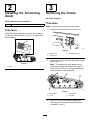
InstallingtheTensioning
Decal
Partsneededforthisprocedure:
2Decal
Procedure
Installthetensioningdecalonaclean,drysurfaceon
thetensiontubeasshowninFigure1onbothsides
ofthemachine.
g203951
Figure1
1.Decal
3
RemovingtheTracks
NoPartsRequired
Procedure
Note:Completetheprocedureforbothtracks.
1.Removethelockingboltandnut(Figure2).
g029758
Figure2
1.Tensiontube3.Tensioningscrew
2.Lockingbolt
2.Loosentherearboltnearthedrivewheelonthe
track(Figure3).
Note:Thisenablesthedrivewheeltopivot
forwardandreleasethetensionofthetrack.If
itdoesnotpivot,turnontheengineandbriey
movethetractioncontrolforward.
g215026
Figure3
1.Drivewheel3.Frontwheel
2.Track4.Rearbolt
3.Usinga1/2-inchdriveratchet,releasethe
drivetensionbyturningthetensioningscrew
clockwise(Figure2).
2

4.Removetheouterfrontwheel(Figure4).
g217640
Figure4
1.Nut
3.Outerfrontwheel
2.Washer(2)
4.Track
5.Removethetrackatthetopoftheinnerfront
wheel,peelingitoffthewheelwhilerotatingthe
trackforward.(Figure4).
6.Whenthetrackisofftheinnerfrontwheel,
removeitfromthedrivewheelandroadwheels
(Figure3).
7.Removethefrontroadwheel(Figure5).
g217543
Figure5
1.Bolt(5/8x8-1/2inches)3.Nut(5/8inch)
2.Frontroadwheel
4
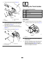
InstallingtheTrackGuides
Partsneededforthisprocedure:
2Template
4
TrackGuide
12Button-headbolt
2Hex-socket-headbolt
2Nut
2Thread-lockingcompound
Procedure
Note:Completetheprocedureforbothtrackframes.
1.Completelycutofftheouterguiderod(Figure6).
g215023
Figure6
1.Guiderod
2.Removeanyweldsontheinsideoroutsideof
thetrackframe.
3.Stackthe2templatesontopofeachother,and
alignthemwiththefrontholeandthebottom
edgeofthetrackframe(Figure7).Usea
hex-socket-headboltandnutinthefrontholeto
securethetemplatestotheframe.
3

g215024
Figure7
1.Nut3.Hex-socket-headboltin
fronthole
2.Templates4.Marktheseholes.
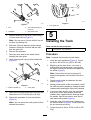
4.Markthelocationsoftheother2holesusinga
1/4-inchcenterdrillbit(Figure7).
Note:Youmayusea1/4-inchdrillbitifyoudo
nothaveacenteringdrill.
5.Drillholes(3/8-inchdiameter)atthemarked
locations,slottingtherearholewiththehole
fromtheguiderod.
6.Removethetemplates.
7.Paintanybaremetalontheframebefore
installingthetrackguide.
8.Installatrackguideusing3button-headbolts
(Figure8).
g215025
Figure8
1.Button-headbolt(3)
2.Trackguide
9.Applythread-lockingcompoundtotheboltsand
torquethemto27to34N∙m(20to25ft-lb).
10.Repeatthisprocedureforinnertrackframe
(Figure9).
Note:Youcanaccesstheinnerguiderodfrom
beneaththemachine.
g217544
Figure9
1.Innerguiderod
5
InstallingtheTrack
Partsneededforthisprocedure:
2
Track(optional,soldseparately)
Procedure
Note:Completetheprocedureforbothtracks.
1.Installthefrontroadwheel(Figure5).T orque
thenutto183to223N∙m(135to165ft-lb).
2.Beginningatthedrivewheel,coilanewor
existingtrackaroundthewheel,ensuringthat
thelugsonthetracktbetweenthespacerson
thewheel(Figure3).
Note:Ensurethatthelugsinthetrackt
betweenthespacersinthemiddleofthedrive
wheel.
3.Pushthetrackunderandbetweentheroad
wheels(Figure3).
4.Startingatthebottomofthefrontwheels,install
thetrackaroundthewheelsbyrotatingthetrack
rearwardwhilepushingthelugsintothewheels.
5.Intheouterfrontwheels,cleantheoldgrease
anddirtoutoftheareabetweenwherethe
washerswereinstalledandthebearingsinside
thewheels,thenllthisareaoneachsideof
eachwheelwithgrease(Figure4).
6.Installtheouterfrontwheeland2washerson
theaxleasshowninFigure4.Securethemwith
thenutremovedpreviously.
7.Torquethenutsto340to475N∙m(250to350
ft-lb).
4

6
AdjustingtheTrackTension
NoPartsRequired
ForNewTracks
1.Forbothtracks,turnthetensioningscrew
counterclockwiseuntilthetensionblockaligns
withthewhitelineclosesttothecurveoftheslot
onthedecal(Figure10).
g203962
Figure10
1.Decal
2.Tensionblock
2.Aligntheclosestnotchinthetensionscrewto
thelocking-boltholeandsecurethescrewwith
thelockingboltandnut.
3.Torquetherearboltto108to122N∙m(80to
90ft-lb).
4.Lowerthemachinetotheground.
5.Drivethemachine,thenparkthemachineona
levelsurface,engagetheparkingbrake,shutoff
theengine,andremovethekey.
6.Verifythatthetensionblockiswithinthegreen
guideofthedecaloris1.3cm(1/2inch)away
fromtherearofthetensiontubeforbothtracks
(Figure10).
Note:Thetracktensionloosensaftersome
use.
7.Removethelockingboltandnut(Figure2).
8.Usinga1/2-inchdriveratchet,turnthetensioning
screwcounterclockwiseuntilthetensionblock
alignswiththegreenguideonthedecaloris1.3
cm(1/2inch)awayfromtherearofthetension
tubeslotforbothtracks(Figure10).
9.Aligntheclosestnotchinthetensionscrewto
thelocking-boltholeandsecurethescrewwith
thelockingboltandnut(Figure2).
ForExistingTracks
1.Removethelockingboltandnut(Figure2).
2.Usinga1/2inchdriveratchet,turnthetensioning
screwcounterclockwiseuntilthetensionnut
alignswiththegreensectionofthedecal(Figure
10).
3.Aligntheclosestnotchinthetensionscrewto
thelocking-boltholeandsecurethescrewwith
thelockingboltandnut(Figure2).
4.Drivethemachine,thenparkthemachineona
levelsurface,engagetheparkingbrake,shutoff
theengine,andremovethekey.
5.Verifythatthetensionblockalignswiththe
greenguideofthedecaloris1.3cm(1/2inch)
awayfromtherearofthetensiontubeforboth
tracks(Figure10).Adjustifnecessary.
5

Notes:

Notes:

-
 1
1
-
 2
2
-
 3
3
-
 4
4
-
 5
5
-
 6
6
-
 7
7
-
 8
8


Toro Wear Block Kit, TX 1000 Wide Track Compact Tool Carrier Installation guide
- Category
- Electrical wallplates
- Type
- Installation guide
Ask a question and I''ll find the answer in the document
Finding information in a document is now easier with AI
Related papers
-
Toro Track Guide Kit, TX 1000 Compact Tool Carrier Installation guide
-
Toro TX 1000 Wide Track Compact Tool Carrier User manual
-
-
-
-
-
-
Toro TX 525 Wide Track Compact Tool Carrier User manual
-
Toro TX 427 Compact Tool Carrier User manual
-