Page is loading ...

Compaq Confidential - Need to Know Required
Writer: Martha Rockecharlie Part Number: xxxxxx-xx1 File Name: a-Intro147.doc
Last Saved On: 3/28/2000 10:48 AM Last Saved By: Martha Rockecharlie
Hardware Reference Guide
Compaq Deskpro Workstation AP230

Compaq Confidential - Need to Know Required
Writer: Martha Rockecharlie Part Number: 178147-001 File Name: b-Notice147.doc
Last Saved On: 3/28/2000 10:49 AM Last Saved By: Martha Rockecharlie
Notice
Compaq Computer Corporation shall not be liable for technical or editorial
errors or omissions contained herein. The information in this guide is subject
to change without notice.
© 2001 Compaq Computer Corporation. Except for use in connection with the accompanying
Compaq product, no part of this guide may be photocopied or reproduced in any form without
prior written consent from Compaq Computer Corporation.
COMPAQ, the Compaq logo, and Deskpro Registered in U.S. Patent and Trademark Office.
Microsoft, Windows, Windows NT, and other names of Microsoft products referenced herein
are trademarks or registered trademarks of Microsoft Corporation.
Intel and Pentium are registered trademarks of Intel Corporation. Celeron and MMX are
trademarks of Intel Corporation.
All other product names mentioned herein may be trademarks or registered trademarks of their
respective companies. Printed in U.S.A.
The following words and symbols mark special messages throughout this guide:
WARNING: Text set off in this manner indicates that failure
to follow directions could result in bodily harm or loss of life.
CAUTION: Text set off in this manner indicates that failure
to follow directions could result in damage to equipment or
loss of information.
Hardware Reference Guide
Compaq Deskpro Workstation AP230
First Edition (March 2001)
Part Number 233953-001
Compaq Computer Corporation

Hardware Reference Guide iii
Compaq Confidential - Need to Know Required
Writer: Martha Rockecharlie Part Number: 178147-001 File Name: c-ToC147.doc
Last Saved On: 3/14/2000 5:18 PM Last Saved By: Lydia Sanchez
CONTENTS
chapter 1
Installation Guidelines
Installation Sequence...............................................................................................................1-1
When to Reconfigure the Computer.........................................................................................1-2
Compaq Configuration Record Utility...............................................................................1-3
chapter 2
Hardware Upgrades
Serviceability Features.............................................................................................................2-1
Removing the Computer Access Panel .............................................................................. 2-1
Removing the Front Bezel..................................................................................................2-3
Removing Bezel Blanks.....................................................................................................2-4
Changing from a Desktop to a Minitower Configuration................................................... 2-5
Changing from a Minitower to a Desktop Configuration................................................... 2-8
Internal Components (Intel 815e Chipset) .............................................................................2-11
Installing Additional Memory................................................................................................2-12
DIMMs............................................................................................................................. 2-12
Memory Module Installation............................................................................................2-12
Installing or Removing an Expansion Card............................................................................2-14
Removing an Expansion Slot Cover.................................................................................2-14
Removing or Installing an Expansion Card...................................................................... 2-15
Drive Positions....................................................................................................................... 2-17
Installing Additional Drives................................................................................................... 2-18
Installing a CD-ROM, DVD-ROM, Tape, or PD-CD Drive............................................ 2-19
Installing a 3.5-Inch Drive into a 5.25-Inch Drive Bay.................................................... 2-21
Removing a Drive from the Drive Bay..................................................................................2-24
appendix A
Specifications
.................................................................................................................................... A-1
appendix B
Computer Setup
Computer Setup Utilities (F10)................................................................................................B-1
appendix C
Hard Drive Installation Guidelines
Using the Cable-Select Feature with Ultra ATA Devices........................................................C-1
Installing SCSI Devices...........................................................................................................C-2
Guidelines for Installing Optional SCSI Devices...............................................................C-2
Cabling for Optional SCSI Devices ...................................................................................C-4
Using SCSISelect with SCSI Devices................................................................................C-5

iv Contents
Compaq Confidential - Need to Know Required
Writer: Martha Rockecharlie Part Number: 178147-001 File Name: c-ToC147.doc
Last Saved On: 3/14/2000 5:18 PM Last Saved By: Lydia Sanchez
appendix D
Battery Replacement
......................................................................................................................... D-1
appendix E
Security Lock Provisions
Installing a Cable Lock............................................................................................................E-1
appendix F
Electrostatic Discharge
Preventing Electrostatic Damage.............................................................................................F-1
Grounding Methods.................................................................................................................F-2
appendix G
Routine Computer Care and Shipping Preparation
Routine Computer Care .......................................................................................................... G-1
CD-ROM Drive Precautions................................................................................................... G-2
Operation........................................................................................................................... G-2
Cleaning............................................................................................................................ G-2
Safety................................................................................................................................ G-2
Shipping Preparation............................................................................................................... G-3
Index .....................................................................................................................................................I-1

Hardware Reference Guide 1-1
Compaq Confidential - Need to Know Required
Writer: Martha Rockecharlie Part Number: 123456-001 File Name: d-Installation.doc
Last Saved On: 3/17/2000 12:22 PM Last Saved By: Lydia Sanchez
chapter
1
INSTALLATION GUIDELINES
This guide explains how to remove the computer cover or access panel
and install the following optional equipment upgrades:
Additional system memory
Expansion card
Optional drive
Security lock
Replacement battery
This chapter includes information about the general installation
sequence for Compaq Deskpro Workstations, and about when to
reconfigure the computer to ensure that it recognizes the newly installed
equipment.
Installation Sequence
It is very important that you follow this sequence of steps to ensure the
proper installation of any optional equipment.
1. If your computer includes the Smart Cover Lock feature and you
have set the lock, use Computer Setup to unlock the lock and
disable the Smart Cover Sensor.
For more information about Computer Setup, refer to Appendix B,
“Computer Setup Utilities.”

1-2 Installation Guidelines
Compaq Confidential - Need to Know Required
Writer: Martha Rockecharlie Part Number: 123456-001 File Name: d-Installation.doc
Last Saved On: 3/17/2000 12:22 PM Last Saved By: Lydia Sanchez
2. If the computer is already on, turn it off and disconnect the power
cord from the wall outlet.
!
WARNING: To reduce the risk of personal injury from electrical
shock and/or hot surfaces, be sure to disconnect the power cord from
the wall outlet, and allow the internal system components to cool
before touching.
!
WARNING: To reduce the risk of electrical shock, fire, or damage to
the equipment, do not plug telecommunications/telephone connectors
into the network interface controller (NIC) receptacles.
CAUTION: Static electricity can damage the electronic components
of the computer or optional equipment. Before beginning these
procedures, ensure that you are discharged of static electricity by
briefly touching a grounded metal object. Refer to Appendix F,
“Electrostatic Discharge,” for more information.
3. Open the computer by removing its outside cover. Refer to the
procedures for removing the computer cover or access panel.
4. Install any optional equipment. Refer to the applicable sections of
this guide or to the documentation provided with the optional
equipment for instructions.
5. Replace the computer cover.
6. Turn on the monitor, computer, and any devices you want to test.
7. Reconfigure the computer, if necessary. Refer Appendix B,
“Computer Setup Utilities,” for instructions about using Computer
Setup.
If you normally lock the Smart Cover Lock, use Computer Setup to
relock the lock and enable the cover removal sensor.
When to Reconfigure the Computer
System configuration is the process of specifying the devices and
programs that make up a computer system. When you add or remove
optional equipment, the computer must be reconfigured to recognize
these changes.

Hardware Reference Guide 1-3
Compaq Confidential - Need to Know Required
Writer: Martha Rockecharlie Part Number: 123456-001 File Name: d-Installation.doc
Last Saved On: 3/17/2000 12:22 PM Last Saved By: Lydia Sanchez
Windows 95 and later operating systems automatically recognize all
Plug and Play devices installed. However, if the device is not a Plug and
Play device or is not automatically detected after installation, follow
these instructions:
In Windows 95 and later operating systems, select the Add New
Hardware icon in the Control Panel and follow the instructions on
the screen.
To reconfigure the computer in Windows NT version 4.0, use the
software utility provided with the newly installed hardware.
Compaq Configuration Record Utility
The Compaq Configuration Record Utility is an online information-
gathering tool similar to other Compaq management tools that run on
computers. It gathers critical hardware and software information from
various sources to give a complete view of the computer configuration.
The Configuration Record Utility delivers a comprehensive
configuration record, provides a means for automatically identifying
and comparing configuration changes, and has the ability to maintain a
computer configuration history. The information can be saved as a
history of multiple sessions.
The Compaq Configuration Record Utility is accessed via an icon in the
Control Panel. When running the utility, information is automatically
gathered on such items as the operating system version number,
operating system parameters, and the operating system startup files. The
utility then combines this information with information on the hardware
configuration to deliver a comprehensive view of the computer.
This utility allows resolution of problems without taking the computer
off-line and assists in maximizing computer availability. The
information obtained by the utility is useful in troubleshooting computer
problems, and streamlines the service process by enabling quick and
easy identification of computer configurations, which is the first step in
resolving service cases.

Hardware Reference Guide 2-1
Compaq Confidential - Need to Know Required
Writer: Martha Rockecharlie Part Number: 178147-xx1 File Name: e-Upgrades147.doc
Last Saved On: 3/14/2000 5:10 PM Last Saved By: Lydia Sanchez
chapter
2
HARDWARE UPGRADES
Serviceability Features
Your computer includes features that make it easier to upgrade and
service.
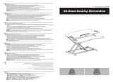
Removing the Computer Access Panel
Before removing the access panel, lay the computer down on its large
base for greater stability.
1. Shut down the operating system properly, then turn off the
computer and any external devices.
2. Disconnect the power cord from the power outlet, and disconnect
any external devices.
CAUTION: Before removing the computer access panel, ensure that
the computer is turned off and that the power cord is disconnected
from the electrical outlet.
3. Loosen the two screws that secure the access panel to the computer
chassis.

2-2 Hardware Upgrades
Compaq Confidential - Need to Know Required
Writer: Martha Rockecharlie Part Number: 178147-xx1 File Name: e-Upgrades147.doc
Last Saved On: 3/14/2000 5:10 PM Last Saved By: Lydia Sanchez
4. Slide the access panel back about 1 inch (2.5 cm), then lift it up and
off the unit.
Removing the Computer Access Panel
To replace the access panel, reverse steps 1–4.

Hardware Reference Guide 2-3
Compaq Confidential - Need to Know Required
Writer: Martha Rockecharlie Part Number: 178147-xx1 File Name: e-Upgrades147.doc
Last Saved On: 3/14/2000 5:10 PM Last Saved By: Lydia Sanchez
Removing the Front Bezel
1. Shut down the operating system properly, then turn off the
computer and any external devices. Disconnect the power cord
from the power outlet and disconnect any external devices.
2. Remove the computer access panel.
3. Push up on the two release tabs
, then rotate the front bezel away
from the chassis to release it
.
Removing the Front Bezel
When replacing the front bezel, ensure that the bottom hinge
points are properly placed in the chassis before rotating the
front bezel back into its original position.

2-4 Hardware Upgrades
Compaq Confidential - Need to Know Required
Writer: Martha Rockecharlie Part Number: 178147-xx1 File Name: e-Upgrades147.doc
Last Saved On: 3/14/2000 5:10 PM Last Saved By: Lydia Sanchez
Removing Bezel Blanks
1. Shut down the operating system properly, then turn off the
computer and any external devices. Disconnect the power cord
from the power outlet and disconnect any external devices.
2. Remove the computer access panel.
3. Remove the front bezel.
4. Gently pull the subpanel, with the bezel blanks secured in it, away
from the front bezel, then remove the desired bezel blank.
CAUTION: Hold the subpanel straight when you pull it away from the
front bezel. Pulling the subpanel away at an angle could damage the
pins that align it within the front bezel.
Removing Bezel Blanks from the Subpanel (Desktop Shown)
When replacing the subpanel, ensure that the aligning pins and
any remaining bezel blanks are in their proper orientation.

Hardware Reference Guide 2-5
Compaq Confidential - Need to Know Required
Writer: Martha Rockecharlie Part Number: 178147-xx1 File Name: e-Upgrades147.doc
Last Saved On: 3/14/2000 5:10 PM Last Saved By: Lydia Sanchez
Changing from a Desktop to a Minitower Configuration
1. Shut down the operating system properly, then turn off the
computer and any external devices. Disconnect the power cord
from the power outlet and disconnect any external devices.
2. Remove the computer access panel.
3. Remove the front bezel.
4. Disconnect all power and data cables from the drives in the 5.25-
inch drive bays.
5. To release the drives from the 5.25-inch drive bay, press the short
(yellow) drivelock
as shown.
Activating the Drivelocks (Shown from the Rear of the Chassis)
6. While pressing the drivelock, pull the drives out of the drive bay.
7. Before you install each drive into the chassis, turn it so that it is in
the same orientation as the internal 3.5-inch drive. The bottom of
the drive should be parallel to the drivelock
.
The diskette drive should always be placed in the bay nearest
the internal 3.5-inch drives in the minitower configuration for
proper clearance within the chassis.

2-6 Hardware Upgrades
Compaq Confidential - Need to Know Required
Writer: Martha Rockecharlie Part Number: 178147-xx1 File Name: e-Upgrades147.doc
Last Saved On: 3/14/2000 5:10 PM Last Saved By: Lydia Sanchez
Installing a Drive in the Minitower Configuration
8. Gently slide the drive into the bay. When the drive is properly
inserted, the drivelock will secure it.
CAUTION: The use of unnecessary force may result in damage to the
drives.
9. Reconnect all power and data cables to the drives in the 5.25-inch
drive bays.
10. Remove the subpanel
as described in the section “Removing
Bezel Blanks” and reposition it with the bezel blanks in the proper
orientation for the minitower configuration
.
CAUTION: Hold the subpanel straight when you pull it away from the
front bezel. Pulling the subpanel away at an angle could damage the
pins that align it within the front bezel.

Hardware Reference Guide 2-7
Compaq Confidential - Need to Know Required
Writer: Martha Rockecharlie Part Number: 178147-xx1 File Name: e-Upgrades147.doc
Last Saved On: 3/14/2000 5:10 PM Last Saved By: Lydia Sanchez
Changing from a Desktop to a Minitower Configuration
11. Replace the subpanel, front bezel, and the computer access panel.
12. Reconnect the external equipment.

2-8 Hardware Upgrades
Compaq Confidential - Need to Know Required
Writer: Martha Rockecharlie Part Number: 178147-xx1 File Name: e-Upgrades147.doc
Last Saved On: 3/14/2000 5:10 PM Last Saved By: Lydia Sanchez
Changing from a Minitower to a Desktop Configuration
1. Shut down the operating system properly, then turn off the
computer and any external devices. Disconnect the power cord
from the power outlet and disconnect any external devices.
2. Remove the computer access panel.
3. Remove the front bezel.
4. Disconnect all power and data cables from the drives in the 5.25-
inch drive bays.
5. To release the drives from the 5.25-inch drive bay, press the long
(green) drivelock
as shown.
Activating the Drivelocks (Shown from the Rear of the Chassis)
6. While pressing the drivelock, pull the drives out of the drive bay.

Hardware Reference Guide 2-9
Compaq Confidential - Need to Know Required
Writer: Martha Rockecharlie Part Number: 178147-xx1 File Name: e-Upgrades147.doc
Last Saved On: 3/14/2000 5:10 PM Last Saved By: Lydia Sanchez
7. Before you install each drive into the chassis, turn it so that it is
perpendicular to the internal 3.5-inch drive. The bottom of the drive
should be parallel to drivelock.
The diskette drive should always be placed in the bay nearest
the top of the chassis in the desktop configuration for proper
drive clearance and access.
Installing a Drive in the Desktop Configuration
8. Gently slide the drive into the bay. When the drive is properly
inserted, the drivelock will secure it.
CAUTION: The use of unnecessary force may result in damage to the
drives.
9. Reconnect all power and data cables to the drives in the 5.25-inch
drive bays.

2-10 Hardware Upgrades
Compaq Confidential - Need to Know Required
Writer: Martha Rockecharlie Part Number: 178147-xx1 File Name: e-Upgrades147.doc
Last Saved On: 3/14/2000 5:10 PM Last Saved By: Lydia Sanchez
10. Remove the subpanel as described in the section “Removing Bezel
Blanks” and reposition it with the bezel blanks in the proper
orientation for the desktop configuration
.
CAUTION: Hold the subpanel straight when you pull it away from the
front bezel. Pulling the subpanel away at an angle could damage the
pins that align it within the front bezel.
Changing from a Minitower to a Desktop Configuration
11. Replace the subpanel, front bezel, and the computer access panel.
12. Reconnect the external equipment.

Hardware Reference Guide 2-11
Compaq Confidential - Need to Know Required
Writer: Martha Rockecharlie Part Number: 178147-xx1 File Name: e-Upgrades147.doc
Last Saved On: 3/14/2000 5:10 PM Last Saved By: Lydia Sanchez
Internal Components (Intel 815e Chipset)
Intel 815e Chipset–Based Internal Components
PCI expansion slots
Processor
Power supply
Memory module sockets
Drivelocks
External drive bays (diskette drive is always in bay 3)
Internal hard drive bays (bays 4 and 5)
Extra drive mounting screws
The number and position of expansion slots may vary by model, as
shown.

2-12 Hardware Upgrades
Compaq Confidential - Need to Know Required
Writer: Martha Rockecharlie Part Number: 178147-xx1 File Name: e-Upgrades147.doc
Last Saved On: 3/14/2000 5:10 PM Last Saved By: Lydia Sanchez
Installing Additional Memory
The computer comes with synchronous dynamic random access
memory (SDRAM) dual inline memory modules (DIMMs).
DIMMs
The memory sockets on the Intel 815e chipset–based system board can
be populated with industry-standard DIMMs. These memory module
slots are populated with at least one preinstalled memory module. To
achieve the maximum memory support, you may be required to replace
the preinstalled DIMM with a higher capacity DIMM.
For proper system operation, the DIMMs must be industry-standard
168-pin, unbuffered PC100– or PC133– compliant SDRAM DIMMs,
depending on the model. The SDRAM DIMMs must support CAS
Latency 2 or 3 (CL = 2 or CL = 3). They must also contain the
mandatory Joint Electronic Device Engineering Council (JEDEC)
Serial Presence Detect (SPD) information. DIMMs constructed with x4
SDRAM are not supported; the system will not start using unsupported
DIMMs.
The Intel 815e chipset supports both PC100 and PC133 SDRAM
DIMMs. PC133 DIMMs should be used for optimal operation. If both
PC100 and PC133 SDRAM DIMMs are installed in a computer, the
system memory will run at the lower 100Mhz speed. Some
configurations of PC133 SDRAMs may run at 100Mhz, instead of
133Mhz.
Memory Module Installation
CAUTION: Your memory module sockets have gold metal contacts.
When upgrading your memory, it is important to use memory
modules with gold metal contacts to prevent corrosion and/or
oxidation resulting from having incompatible metals in contact with
each other.
CAUTION: Static electricity can damage the electronic components
of the computer or optional cards. Before beginning these
procedures, ensure that you are discharged of static electricity by
briefly touching a grounded metal object. Refer to Appendix F,
“Electrostatic Discharge,” for more information.
CAUTION: When handling a memory module, be careful not to touch
any of the contacts. Doing so may damage the module.

Hardware Reference Guide 2-13
Compaq Confidential - Need to Know Required
Writer: Martha Rockecharlie Part Number: 178147-xx1 File Name: e-Upgrades147.doc
Last Saved On: 3/14/2000 5:10 PM Last Saved By: Lydia Sanchez
1. If you have locked the Smart Cover Lock, use Computer Setup to
unlock the lock and disable the Smart Cover Sensor.
2. Shut down the operating system properly, then turn off the
computer and any external devices, then disconnect the power cord
from the power outlet.
3. Remove the access panel and locate the memory module sockets.
!
WARNING: To reduce risk of personal injury from hot surfaces, allow
the internal system components to cool before touching.
4. Open both latches of the memory module socket , and insert the
memory module into the socket
.
Begin by installing a module into the socket nearest the preinstalled
module, and install the modules following the numerical order of
the sockets.
A memory module can be installed in only one way. Match the
notch on the module with the tab on the memory socket. Push the
module down into the socket, ensuring that the module is fully
inserted and properly seated
.
Installing a DIMM
/