Page is loading ...

—
ABB MEASUREMENT & ANALYTICS | OPERATING INSTRUCTION
CoriolisMaster FCB400, FCH400
Coriolis mass flowmeter
—
ABB Limited
Measurement & Analytics
Howard Road, St. Neots
Cambridgeshire, PE19 8EU
UK
Tel: +44 (0)870 600 6122
Fax: +44 (0)1480 213 339
Email: [email protected]m
ABB Automation Products GmbH
Measurement & Analytics
Schillerstr. 72
32425 Minden
Germany
Tel: +49 571 830-0
Fax: +49 571 830-1806
abb.com/flow
ABB Inc.
Measurement & Analytics
125 E. County Line Road
Warminster, PA 18974
USA
Tel: +1 215 674 6000
Fax: +1 215 674 7183
Device firmware version: 00.05.00
Measurement made easy
OI/FCB400/FCH400-EN Rev. E 01.2019
—
CoriolisMaster FCB430 / 450
CoriolisMaster FCH430 / 450
Introduction
With no up or downstream piping requirements
the compact Coriolis flowmeters can be installed
in the tightest spaces, enabling applications not
possible before.
CoriolisMaster FCB400
The compact Coriolis mass flowmeters from the
CoriolisMaster FCB400 series offer low pressure
drop, high capacity, an intuitive ABB display
featuring a standardized design and cross-
product compatibility, five modular inputs and
outputs as well as HART communication.
CoriolisMaster FCH400
The compact Coriolis mass flowmeters for
hygienic applications from the CoriolisMaster
FCH400 series additionally offer EHEDG certified
cleanability; all wetted materials are polished.
Additional Information
Additional documentation on CoriolisMaster
FCB400, FCH400 is available for download free of
charge at www.abb.com/flow.
Alternatively simply scan this code:
—
We reserve the right to make technical changes or modify the contents of this document
without prior notice. With regard to purchase orders, the agreed particulars shall prevail.
ABB does not accept any responsibility whatsoever for potential errors or possible lack of
information in this document.
We reserve all rights in this document and in the subject matter and illustrations contained
therein. Any reproduction, disclosure to third parties or utilization of its contents – in whole
or in parts – is forbidden without prior written consent of ABB.
© ABB 2019 3KXF411010R4201

2 CoriolisMaster FCB400, FCH400 CORIOLIS MASS FLOWMETER | OI/FCB400/FCH400-EN REV. E
Table of contents
Change from one to tw o columns
1 Safety .......................................................................... 4
General information and instructions .................................. 4
Warnings .................................................................................... 4
Intended use ............................................................................. 5
Improper use ............................................................................. 5
Notes on data safety ............................................................... 5
Warranty provisions ................................................................. 5
Manufacturer’s address .......................................................... 5
2 Use in potentially explosive atmospheres ............. 6
Device overview ........................................................................ 6
ATEX / IECEx ........................................................................ 6
cFMus .................................................................................... 7
Ex marking ................................................................................. 8
Description of model numbers ......................................... 8
ATEX / IECEx ...................................................................... 10
cFMus .................................................................................. 11
Temperature data .................................................................. 12
Temperature resistance for the connecting cable ...... 12
Environmental and process conditions for model
FCx4xx… ............................................................................. 12
Measuring medium temperature for sensors in
integral mount design with dual-compartment
housing ................................................................................ 13
Measuring medium temperature for sensors in
integral mount design with single-compartment
housing ................................................................................ 14
Measuring medium temperature for sensors in remote
mount design ..................................................................... 15
Electrical data ......................................................................... 16
Overview ............................................................................. 16
Zone 2, 21 and Division 2 – Model: FCx4xx-A2, FCx4xx-
F2 .......................................................................................... 17
Zone 1 ,21 und Division 1 – Model: FCx4xx-A1, FCx4xx-
F1 .......................................................................................... 18
Special connection conditions ........................................ 19
Installation instructions ........................................................ 20
ATEX / IECEx ...................................................................... 20
cFMus .................................................................................. 20
Use in areas exposed to combustible dust .................. 20
Opening and closing the housing .................................. 20
Cable entries in accordance with ATEX / IECEx ........... 21
Cable entries in accordance with cFMus ....................... 21
Electrical connections ...................................................... 22
Process sealing .................................................................. 22
Operating instructions .......................................................... 23
Protection against electrostatic discharges ................ 23
Repair................................................................................... 23
Changing the type of protection .................................... 24
3 Design and function ................................................ 25
General ..................................................................................... 25
Measuring principle ............................................................... 25
Device designs ........................................................................ 26
4 Product identification ............................................ 28
Name plate .............................................................................. 28
5 Transport and storage ........................................... 29
Inspection ............................................................................... 29
Transporting the device ....................................................... 29
Storing the device .................................................................. 30
Ambient conditions .......................................................... 30
Returning devices .................................................................. 30
6 Installation ................................................................ 31
General installation conditions ............................................ 31
Installation location and assembly ................................. 31
Liquid measuring media .................................................. 32
Gaseous measuring media .............................................. 33
Turn-off devices for the zero point adjustment .............. 33
Sensor insulation ................................................................... 34
Heat tracing of the sensor .............................................. 34
Devices for legal metrology in accordance with
MID / OIML R117 ..................................................................... 34
Process conditions ................................................................ 35
Temperature limits °C (°F) .............................................. 35
Pressure ratings ................................................................ 35
Housing as a protective device (optional) ................... 35
Material load for process connections .............................. 35
Material load curves for flange devices ........................ 36
Installing the sensor .............................................................. 37
Installing the transmitter in the remote mount design . 37
Opening and closing the housing ....................................... 38
Dual- compartment housing ........................................... 39
Single-compartment housing ......................................... 39
Adjusting the transmitter position .................................... 40
Transmitter housing ........................................................ 40
Rotate LCD indicator – dual-compartment housing .. 40
Installing the plug-in cards .................................................. 42
7 Electrical connections ............................................ 46
Safety instructions ................................................................ 46
Power supply .......................................................................... 46
Installing the connection cables ......................................... 47
Recommended cables ...................................................... 47
Pin assignment ....................................................................... 48
Electrical data for inputs and outputs .......................... 49
Connection examples ....................................................... 53
Connection to integral mount design ........................... 56
Connection to remote mount design............................ 58
Digital communication ......................................................... 61
HART® Communication .................................................... 61
Modbus® communication ............................................... 61
Cable specification ........................................................... 62
PROFIBUS DP® communication ...................................... 62
8 Commissioning ....................................................... 64
Hardware settings ................................................................. 64
Dual- compartment housing ........................................... 64
Single-compartment housing ......................................... 65
Configuration of digital outputs V1 / V2 or V3 / V4 ... 65
Checks prior to commissioning .......................................... 66

CoriolisMaster FCB400, FCH400 CORIOLIS MASS FLOWMETER | OI/FCB400/FCH400-EN REV. E 3
Switching on the power supply .......................................... 66
Parameterization of the device .......................................... 66
Installation of ABB AssetVision Basic and ABB Field
Information Manager (FIM) ............................................ 66
Parameterization via the infrared service port adapter
............................................................................................. 69
Parameterization via HART® ........................................... 69
Basic Setup .............................................................................. 70
Menu: Easy Set-up ............................................................. 70
9 Operation ................................................................. 72
Safety instructions ................................................................. 72
Menu navigation ..................................................................... 72
Menu levels .............................................................................. 73
Process display ....................................................................... 74
Switching to the information level ...................................... 74
Error messages on the LCD display ............................... 75
Switching to the information level ...................................... 75
Resetting the customer password................................. 76
Selecting and changing parameters ................................... 77
Available units ......................................................................... 78
Available process variables ................................................. 80
Parameter overview ............................................................... 83
Parameter descriptions ........................................................ 95
Menu: Easy Set-up ............................................................. 95
Menu: Device Info .............................................................. 97
Menu: Device Setup .......................................................... 99
Menu: Display ................................................................... 106
Menu: Input / Output...................................................... 107
Menu: Process Alarm ...................................................... 112
Menu: Communication ................................................... 113
Menu: Diagnostics ........................................................... 115
Menu: Totalizer ................................................................ 119
Software history ................................................................... 121
Zero point balance under operating conditions ............ 121
Measurement of standard volumes .................................. 122
VeriMass erosion monitor .................................................. 124
Setup ................................................................................. 124
Concentration measurement DensiMass ........................ 125
Calculating standard volumes and standard densities
of liquids ........................................................................... 125
Accuracy of the concentration measurement ............ 126
Entering the concentration matrix .............................. 126
FillMass batch function ....................................................... 129
Setup ................................................................................. 130
10 Diagnosis / error messages ................................. 131
Calling up the error description ........................................ 131
General ................................................................................... 131
Overview ................................................................................ 132
Error messages ..................................................................... 134
11 Maintenance ........................................................... 138
Safety instructions ............................................................... 138
Sensor .................................................................................... 138
Cleaning ................................................................................. 138
12 Repair ...................................................................... 138
Safety instructions ............................................................... 138
Spare parts ........................................................................... 139
Replacing the fuse ............................................................... 139
Replacing the LCD indicator .............................................. 140
Replacing the frontend board ............................................ 141
Integral mount design .................................................... 141
Remote mount design ................................................... 143
Replacing the sensor ........................................................... 144
Returning devices ................................................................ 144
13 Dismounting and disposal ................................... 145
Dismounting ......................................................................... 145
Disposal ................................................................................. 145
14 Specification ......................................................... 146
15 Additional documents .......................................... 146
16 Appendix ................................................................. 147
Return form ........................................................................... 147

4 CoriolisMaster FCB400, FCH400 CORIOLIS MASS FLOWMETER | OI/FCB400/FCH400-EN REV. E
1 Safety
General information and instructions
These instructions are an important part of the product and
must be retained for future reference.
Installation, commissioning, and maintenance of the product
may only be performed by trained specialist personnel who have
been authorized by the plant operator accordingly. The specialist
personnel must have read and understood the manual and must
comply with its instructions.
For additional information or if specific problems occur that are
not discussed in these instructions, contact the manufacturer.
The content of these instructions is neither part of nor an
amendment to any previous or existing agreement, promise or
legal relationship.
Modifications and repairs to the product may only be performed
if expressly permitted by these instructions.
Information and symbols on the product must be observed.
These may not be removed and must be fully legible at all times.
The operating company must strictly observe the applicable
national regulations relating to the installation, function testing,
repair and maintenance of electrical products.
Warnings
The warnings in these instructions are structured as follows:
DANGER
The signal word ‘DANGER’ indicates an imminent danger.
Failure to observe this information will result in death or
severe injury.
WARNING
The signal word ‘WARNING’ indicates an imminent danger.
Failure to observe this information may result in death or
severe injury.
CAUTION
The signal word ‘CAUTION’ indicates an imminent danger.
Failure to observe this information may result in minor or
moderate injury.
NOTICE
The signal word
‘
NOTIC
E
’
indicates possible material damage.
Note
‘Note’ indicates useful or important information about the
product.

CoriolisMaster FCB400, FCH400 CORIOLIS MASS FLOWMETER | OI/FCB400/FCH400-EN REV. E 5
Intended use
This device is intended for the following uses:
• To convey liquids and gases (including unstable measuring
media).
• To meter mass flow directly.
• To meter volumetric flow (indirectly via mass flow and
density).
• To measure the density of the measuring medium.
• To measure the temperature of the measuring medium.
The device has been designed for use exclusively within the
technical limit values indicated on the identification plate and in
the data sheets.
When using measuring media, the following points must be
observed:
• Measuring media may only be used if, based on the state
of the art or the operating experience of the user, it can
be assured that the chemical and physical properties
necessary for operational security of the materials of the
wetted parts of the temperature sensor will not be
adversely affected during the operating time.
• Media containing chloride in particular can cause
corrosion damage to stainless steels which, although not
visible externally, can damage wetted parts beyond repair
and lead to the measuring medium escaping. It is the
operator's responsibility to check the suitability of these
materials for the respective application.
• Measuring media with unknown properties or abrasive
measuring media may only be used if the operator is able
to perform regular and suitable tests to ensure the safe
condition of the device
Improper use
The following are considered to be instances of especially
improper use of the device:
• Operation as a flexible compensating adapter in piping,
for example for compensating pipe offsets, pipe
vibrations, pipe expansions, etc.
• For use as a climbing aid, for example for mounting
purposes.
• For use as a bracket for external loads, for example as a
support for piping, etc.
• Material application, for example by painting over the
housing, name plate or welding/soldering on parts.
• Material removal, for example by spot drilling the
housing.
Notes on data safety
This product is designed to be connected to and to
communicate information and data via a network interface.
It is operator’s sole responsibility to provide and continuously
ensure a secure connection between the product and your
network or any other network (as the case may be).
Operator shall establish and maintain any appropriate measures
(such as but not limited to the installation of firewalls,
application of authentication measures, encryption of data,
installation of anti-virus programs, etc.) to protect the product,
the network, its system and the interface against any kind of
security breaches, unauthorized access, interference, intrusion,
leakage and / or theft of data or information.
ABB Automation Products GmbH and its affiliates are not liable
for damages and / or losses related to such security breaches,
any unauthorized access, interference, intrusion, leakage and /
or theft of data or information.
Warranty provisions
Using the device in a manner that does not fall within the scope
of its intended use, disregarding this manual, using
underqualified personnel, or making unauthorized alterations
releases the manufacturer from liability for any resulting
damage. This renders the manufacturer's warranty null and void.
Manufacturer’s address
ABB Automation Products GmbH
Measurement & Analytics
Dransfelder Str. 2
37079 Goettingen
Germany
Tel: +49 551 905-0
Fax: +49 551 905-777
Email: vertrieb.messtechnik-produkt[email protected]
Customer service center
Tel: +49 180 5 222 580
Email: [email protected]
Change from two to one column

6 CoriolisMaster FCB400, FCH400 CORIOLIS MASS FLOWMETER | OI/FCB400/FCH400-EN REV. E
2 Use in potentially explosive atmospheres
Note
Further information on the Ex-Approval of devices can be found in the type examination certificates or the relevant certificates at
www.abb.com/flow .
Device overview
ATEX / IECEx
Standard / No explosion protection Zone 2, 21, 22 Zone 1, 21 (Zone 0)
Model number FCx4xx Y0 FCx4xx A2 FCx4xx A1
Integral mount design
• Standard
• Zone 2, 21, 22
• Zone 1, 21
• Zone 0
Model number FCT4xx Y0 FCx4xx Y0 FCT4xx A2 FCx4xx A2 FCT4xx A1 FCx4xx A1
Remote mount design
Transmitter and
flowmeter sensor
• Standard
• Zone 2, 21, 22
• Zone 1, 21
• Zone 0
Model number FCT4xx Y0 FCT4xx A2 FCx4xx A1
Remote mount design
Transmitter
• Standard
• Zone 2, 21, 22
Sensor
• Zone 1, 21
• Zone 0
Model number — FCT4xx A2 FCx4xx A1
Remote mount design
Transmitter
• Zone 2, 21, 22
Sensor
• Zone 1, 21
—
1 Single-compartment housing
2 Dual-compartment housing
3 Zone 0 within the meter tube

CoriolisMaster FCB400, FCH400 CORIOLIS MASS FLOWMETER | OI/FCB400/FCH400-EN REV. E 7
cFMus
Standard / No explosion protection Class I Div. 2 / Zone 2 Class I Div. 1 / Zone 1 (Zone 0)
Model number FCx4xx Y0 FCx4xx F2 FCx4xx F1
Integral mount design
• Standard
• Div. 2 / Zone 2
• Div. 1 / Zone 1
(Zone 0)
Model number FCT4xx Y0 FCx4xx Y0 FCT4xx F2 FCx4xx F2 FCT4xx F1 FCx4xx F1
Remote mount design
Transmitter and
flowmeter sensor
• Div. 2 / Zone 2
• Div. 1 / Zone 1
(Zone 0)
Model number FCT4xx Y0 FCT4xx F2 FCx4xx F1
Remote mount design
Transmitter
• Standard
Sensor
• Div. 2 / Zone 2
• Div. 1 / Zone 1
(Zone 0)
Model number — FCT4xx F2 FCx4xx F1
Remote mount design
Transmitter
• Div. 2 / Zone 2
Sensor
• Div. 1 / Zone 1
(Zone 0)
—
1 Single-compartment housing
2 Dual-compartment housing
3 Zone 0 within the meter tube

8 CoriolisMaster FCB400, FCH400 CORIOLIS MASS FLOWMETER | OI/FCB400/FCH400-EN REV. E
… 2 Use in potentially explosive atmospheres
Ex marking
Description of model numbers
Each device design has a specific model number. The parts of the model number relating to explosion protection are listed in the
following table. The complete key to model numbers is described in the device data sheet.
Basic model
FCa4c d m f g h i j k l m
Explosion protection
Without
Y0
ATEX / IECEx (Zone 2 / 22)
A2
ATEX / IECEx (Zone 1 / 21)
A1
cFMus version, Class 1, Div. 2 (Zone 2 / 21)
F2
cFMus version, Class 1, Div. 1 (Zone 1 / 21)
F1
NEPSI (Zone 2 / 22)
S2
NEPSI (Zone 1 / 21)
S1
Design / terminal box material / cable glands
Integral mount - see transmitter housing
Y0
Remote mount / aluminum / 1 × M20 × 1.5
U1
Remote mount / aluminum / 1 × NPT ½ in
U2
Remote mount / stainless steel / 1 × M20 × 1.5
A1
Remote mount / stainless steel / 1 × NPT ½ in
A2
Nominal diameter / nominal connection diameter
xxxxx
Process connection
xx
Material for wetted parts
Stainless steel
A1
Polished stainless steel H1
Nickel alloy
C1
Flow rate calibration
x
Density calibration
x

CoriolisMaster FCB400, FCH400 CORIOLIS MASS FLOWMETER | OI/FCB400/FCH400-EN REV. E 9
Basic model
FCa4c d m f g h i j k l m
Design / transmitter housing / transmitter housing material / cable gland
Integral mount / dual-compartment housing / aluminum / 3 × M20 × 1.5
D1
Integral mount / dual-compartment housing / aluminum / 3 × NPT ½ in D2
Integral mount / dual-compartment housing / aluminum / 3 × M20 × 1.5 (Ex d / XP)
D5
Integral mount / dual-compartment housing / aluminum / 3 × NPT ½ in (Ex d / XP) D6
Integral mount / dual-compartment housing / stainless steel / 3 × M20 × 1.5
D3
Integral mount / dual-compartment housing / stainless steel / 3 × NPT ½ in D4
Integral mount / dual-compartment housing / stainless steel / 3 × M20 × 1.5 (Ex d /
XP)
D7
Integral mount / dual-compartment housing / stainless steel / 3 × NPT ½ in (Ex d /
XP)
D8
Integral mount / single-compartment housing / aluminum / 3 × M20 × 1.5 S1
Integral mount / single-compartment housing / aluminum / 3 × NPT ½ in
S2
Remote mount / dual-compartment housing / aluminum / 3 × M20 × 1.5
R1
Remote mount / dual-compartment housing / aluminum / 3 × NPT ½ in
R2
Remote mount / dual-compartment housing / aluminum / 3 × M20 × 1.5 (Ex d / XP)
R5
Remote mount / dual-compartment housing / aluminum / 3 × NPT ½ in (Ex d / XP)
R6
Remote mount / dual-compartment housing / stainless steel / 3 × M20 × 1.5
R3
Remote mount / dual-compartment housing / stainless steel / 3 × NPT ½ in
R4
Remote mount / dual-compartment housing / stainless steel / 3 × M20 × 1.5 (Ex d /
XP)
R7
Remote mount / dual-compartment housing / stainless steel / 3 × NPT ½ in (Ex d /
XP)
R8
Remote mount / single-compartment housing, wall mounting / aluminum /
4 × M20 × 1.5
W1
Remote mount / single-compartment housing, wall mounting / aluminum / 4 × NPT
½ in
W2
Remote mount / not specified
Y0
Outputs
Current output 1 (active or passive), digital output 1 & 2 (passive),
HART®, PROFIBUS DP®
D1
Current output 1 (active), digital output 1 & 2 (passive), HART®, Modbus® M1*
Current output 1 (active / passive), digital output 1 & 2 (passive), HART
G0
Current output 1 (active / passive), digital output 1 & 2 (passive),
24 V DC transmitter loop power supply, HART®
G1
Current output 1 (active / passive), digital output 1 & 2 (passive),
current output 2 (passive), HART®
G2
Current output 1 (active / passive), digital output 1 & 2 (passive),
current output 2 (passive), current output 3 (passive), HART®
G3
Current output 1 (active / passive), digital output 1 & 2 (passive),
current output 2 (passive), 24 V DC transmitter loop power supply, HART®
G4
Without Y0
Power supply
100 to 230 V AC
A
11 to 30 V DC
C
Without
Y
* The M1 design is identical in construction to the M5 design, as it can also be called in other locations

10 CoriolisMaster FCB400, FCH400 CORIOLIS MASS FLOWMETER | OI/FCB400/FCH400-EN REV. E
… 2 Use in potentially explosive atmospheres
… Ex marking
ATEX / IECEx
Note
• A specific marking applies, depending on the design.
• ABB reserves the right to modify the Ex-marking. Refer to the name plate for the exact marking.
Model number for use in Zone 2, 21 Ex marking Certificate
FCa4c – A2Y0fghijD
Integral mount design with dual-compartment
housing
II3G Ex ec IIC T6...T1 Gc
II2D Ex tc IIIC T80°C...Tmedium Dc
ATEX:
FM15ATEX0014X, FM15ATEX0016X
IECEx:
IECEx FME 15.0005X
FCa4c – A2efghijY
Sensor in remote mount design with dual-
compartment housing
FCT4c – A2R
Transmitter in remote mount design with dual-
compartment housing
II3G Ex ec IIC T6 Gc
II2D Ex tc IIIC T80°C Dc
Model number for use in Zone 1, 21 Ex marking Certificate
FCa4c – A1Y0fghijDx (x = 1 to 4)
Integral mount design with dual-compartment
housing
II 1/2 (1) G Ex db eb ia mb [ia Ga] IIC T6…T1 Gb
II 2 (1) D Ex ia tb [ia Da] IIIC T80°C Db
ATEX:
FM15ATEX0015X
IECEx:
IECEx FME 15.0005X
FCa4c – A1Y0fghijDx (x = 5 to 8)
Integral mount design with dual-compartment
housing (flameproof enclosure ‘Ex d’)
II 1/2 (1) G Ex db ia mb [ia Ga] IIB+H2 T6...T1 Gb
II 2 (1) D Ex ia tb [ia Da] IIIC T80°C Db
FCa4c – A1efghijY
Sensor in remote mount design with dual-
compartment housing
II 1/2 G Ex eb ia mb IIB+H2 T6…T1 Ga/Gb
II 2 D Ex ia tb IIIC T80°C Db
FCT4c – A1R (x = 1 to 4)
Transmitter in remote mount design with dual-
compartment housing
II 2 (1) G Ex db e ia mb [ia Ga] IIC T6…T1 Gb
II 2 (1) D Ex ia mb tb [ia Da] IIIC T80°C Db
FCT4c – A1R (x = 5 to 8)
Transmitter in remote mount design with dual-
compartment housing
(flameproof enclosure ‘Ex d’)
II 2 (1) G Ex db ia mb [ia Ga] IIB+H2 T6…T1 Gb
II 2 (1) D Ex ia tb [ia Da] IIIC T80°C Db

CoriolisMaster FCB400, FCH400 CORIOLIS MASS FLOWMETER | OI/FCB400/FCH400-EN REV. E 11
cFMus
Note
• A specific marking applies, depending on the design.
• ABB reserves the right to modify the Ex-marking. Refer to the name plate for the exact marking.
Model number for use in Division 2 Ex marking Certificate
FCa4c – F2Y0fghijD
Integral mount design with dual-compartment housing
NI: CL I,II,III Div 2, GPS ABCDEFG, T6…T1
DIP: CL II,III, Div 1, GPS EFG, T6
CL I, ZN 2, AEx ec IIC T6…T1 (USA)
ZN 21, AEx ia tb IIIC T80°C (USA)
CL I, ZN 2, Ex ec IIC T6...T1 (CAN)
ZN21,Ex ia tb IIIC T80°C (CAN)
See handbook for temperature class information
cFMus:
3050239
FCa4c – F2efghijY
Sensor in remote mount design with dual-compartment housing
Design in accordance with ANSI / ISA 12.27.01 as ‘Single Seal Device’
or as ‘Dual Seal Device’ (option TE2)
FCT4c – F2R
Transmitter in remote mount design with dual-compartment housing
Model number for use in Division 1 Ex marking Certificate
FCa4c – F1Y0fghijDx (x = 1 to 4)
Integral mount design with dual-compartment housing
XP-IS: CL I, Div 1, GPS ABCD,T6…T1 (USA)
XP-IS: CL I, Div 1, GPS BCD,T6…T1 (CAN)
DIP: CL II,III, Div 1, GPS EFG,T6
CL I, ZN 1, AEx db ia IIB+H2 T6…T1 (USA)
ZN21, AEx ia tb IIIC T80°C (USA)
CL I, ZN 1, Ex db ia IIB+H2 T6…T1 (CAN)
ZN21, Ex ia tb IIIC T80°C (CAN)
See handbook for temperature class information and installation
drawing 3KXF000028G0009
cFMus:
3050239
FCa4c – F1Y0fghijDx (x = 5 to 8)
Integral mount design with dual-compartment housing
(Explosionproof ‘XP’).
Design in accordance with ANSI / ISA 12.27.01 as ‘Single Seal Device’
or as ‘Dual Seal Device’ (option TE2)
FCa4c – F1efghijY
Sensor in remote mount design with dual-compartment housing
XP-IS: CL I, Div 1, GPS BCD T6…T1 (USA)
DIP: CL II,III, Div 1, GPS EFG,T6
CL I, ZN 1, AEx db ia IIB+H2 T6…T1 (USA)
ZN 21, AEx ia tb IIIC T80°C (USA)
CL I, ZN 1, Ex db ia IIB+H2 T6…T1 (CAN)
ZN21, Ex ia tb IIIC T80°C (CAN)
See handbook for temperature class information and installation
drawing 3KXF000028G0009
Design in accordance with ANSI / ISA 12.27.01 as ‘Single Seal Device’
or as ‘Dual Seal Device’ (option TE2)
FCT4c – F1Rx (x = 1 to 4)
Transmitter in remote mount design with dual-compartment housing
XP-IS: CL I, Div 1, GPS BCD,T6…T1 (USA) XP-IS: CL I, Div 1, GPS
BCD,T6…T1 (CAN)
DIP: CL II,III, Div 1, GPS EFG, T6
CL I, ZN 1, AEx db ia IIB+H2 T6…T1 (USA)
ZN 21, AEx ia tb IIIC T80°C (USA)
CL I, ZN 1, Ex db ia IIB+H2 T6…T1 (CAN)
ZN21,Ex ia tb IIIC T80°C (CAN)
See handbook for temperature class information and installation
drawing 3KXF000028G0009
FCT4c – F1Rx (x = 5 to 8)
Sensor in remote mount design with dual-compartment housing
(Explosionproof ‘XP’).
Change from one to tw o columns

12 CoriolisMaster FCB400, FCH400 CORIOLIS MASS FLOWMETER | OI/FCB400/FCH400-EN REV. E
… 2 Use in potentially explosive atmospheres
Temperature data
Temperature resistance for the connecting cable
The temperature at the cable entries of the device depends on
the design, the measuring medium temperature T
medium
and the
ambient temperature T
amb.
.
For the electric connection of the device, use only cables with
sufficient temperature resistance in accordance with the
following table.
Devices in integral mount design with dual-compartment
housing
T
amb.
Temperature resistance
≤ 50 °C (≤ 122 °F) ≥ 70 °C (≥ 158 °F)
≤ 60 °C (≤ 140 °F) ≥ 80 °C (≥ 176 °F)
≤ 70 °C (≤ 158 °F) ≥ 90 °C (≥ 194 °F)
Devices in integral mount design with single-compartment
housing
T
amb.
Temperature resistance
≤ 50 °C (≤ 122 °F) ≥ 75 °C (≥ 167 °F)
≤ 60 °C (≤ 140 °F) ≥ 85 °C (≥ 185 °F)
≤ 70 °C (≤ 158 °F) ≥ 95 °C (≥ 203 °F)
Sensor in remote mount design
T
amb.
Temperature resistance
≤ 50 °C (≤ 122 °F) ≥ 105 °C (≥ 221 °F)
≤ 60 °C (≤ 140 °F) ≥ 110 °C (≥ 230 °F)
≤ 70 °C (≤ 158 °F) ≥ 120 °C (≥ 248 °F)
For sensors in remote mount design, the wires in the connection
box must be additionally insulated with the enclosed silicone
hoses starting from ambient temperatures of T
amb.
≥ 60 °C
(≥ 140 °F).
Environmental and process conditions for model
FCx4xx…
Ambient temperature T
amb.
-20 to 70 °C
(-4 to 158 °F)
-40 to 70 °C*
(-40 to 158 °F)*
Measuring medium temperature
T
medium
-40 to 205 °C
(-40 to 400 °F)
IP rating / NEMA rating IP 65, IP 67 /
NEMA 4X,Type 4X
* Optional, with order code ‘Ambient temperature range – TA9’
Change from two to one column

CoriolisMaster FCB400, FCH400 CORIOLIS MASS FLOWMETER | OI/FCB400/FCH400-EN REV. E 13
Measuring medium temperature for sensors in integral mount design with dual-compartment housing
Model FCx4xx-A1… and FCx4xx-F1… in Zone 1, Division 1
The table shows the maximum permissible measuring medium temperature as a function of ambient temperature and temperature
class.
Temperature class
Ambient temperature T
amb.
T1 T2 T3 T4 T5 T6
≤ 30 °C (≤ 86 °F) 205 °C (400 °F)*
130 °C (266 °F)
205 °C (400 °F)*
130 °C (266 °F)
195 °C (383 °F)*
130 °C (266 °F)
130 °C (266 °F) 95 °C (203 °F) 80 °C (176 °F)
≤ 40 °C (≤ 104 °F) 205 °C (400 °F)*
130 °C (266 °F)
205 °C (400 °F)*
130 °C (266 °F)
195 °C (383 °F)*
130 °C (266 °F)
130 °C (266 °F) 95 °C (203 °F) 80 °C (176 °F)
≤ 50 °C (≤ 122 °F) 205 °C (400 °F)*
130 °C (266 °F)
205 °C (400 °F)*
130 °C (266 °F)
195 °C (383 °F)*
130 °C (266 °F)
130 °C (266 °F) 95 °C (203 °F) 80 °C (176 °F)
≤ 60 °C (≤ 140 °F) 205 °C (400 °F)*
130 °C (266 °F)
205 °C (400 °F)*
130 °C (266 °F)
195 °C (383 °F)*
130 °C (266 °F)
130 °C (266 °F) 95 °C (203 °F) 80 °C (176 °F)
≤ 70 °C (≤ 158 °F) 205 °C (400 °F)*
130 °C (266 °F)
205 °C (400 °F)*
130 °C (266 °F)
195 °C (383 °F)*
130 °C (266 °F)
130 °C (266 °F) 95 °C (203 °F) 80 °C (176 °F)
* Only with the ‘Extended tower length – TE1, TE2 or TE3’ order option
Model FCx4xx-A2… and FCx4xx-F2… in Zone 2, Division 2
The table shows the maximum permissible measuring medium temperature as a function of ambient temperature and temperature
class.
Temperature class
Ambient temperature T
amb.
T1 T2 T3 T4 T5 T6
≤ 30 °C (≤ 86 °F) 205 °C (400 °F) 205 °C (400 °F) 195 °C (383 °F)*
130 °C (266 °F)
130 °C (266 °F) 95 °C (203 °F) 80 °C (176 °F)*
60 °C (140 °F)
≤ 40 °C (≤ 104 °F) 205 °C (400 °F) 205 °C (400 °F) 195 °C (383 °F)*
130 °C (266 °F)
130 °C (266 °F) 95 °C (203 °F) —
≤ 50 °C (≤ 122 °F) 205 °C (400 °F) 205 °C (400 °F) 195 °C (383 °F)*
130 °C (266 °F)
130 °C (266 °F) — —
≤ 60 °C (≤ 140 °F) 205 °C (400 °F) 205 °C (400 °F) 195 °C (383 °F)*
130 °C (266 °F)
130 °C (266 °F) — —
≤ 70 °C (≤ 158 °F) 205 °C (400 °F)*
130 °C (266 °F)
205 °C (400 °F)*
130 °C (266 °F)
195 °C (383 °F)*
130 °C (266 °F)
130 °C (266 °F) — —
* Only with the ‘Extended tower length – TE1, TE2 or TE3’ order option

14 CoriolisMaster FCB400, FCH400 CORIOLIS MASS FLOWMETER | OI/FCB400/FCH400-EN REV. E
… 2 Use in potentially explosive atmospheres
… Temperature data
Measuring medium temperature for sensors in integral mount design with single-compartment housing
Model FCx4xx-A2… and FCx4xx-F2… in Zone 2, Division 2
The table shows the maximum permissible measuring medium temperature as a function of ambient temperature and temperature
class.
Temperature class
Ambient temperature T
amb.
T1 T2 T3 T4 T5 T6
≤ 30 °C (≤ 86 °F) 205 °C (400 °F) 205 °C (400 °F) 195 °C (383 °F) 130 °C (266 °F) 95 °C (203 °F) 80 °C (176 °F)
≤ 40 °C (≤ 104 °F) 205 °C (400 °F) 205 °C (400 °F) 195 °C (383 °F) 130 °C (266 °F) 95 °C (203 °F) —
≤ 50 °C (≤ 122 °F) 205 °C (400 °F) 205 °C (400 °F) 195 °C (383 °F) 130 °C (266 °F) 95 °C (203 °F) —
≤ 60 °C (≤ 140 °F) 205 °C (400 °F) 205 °C (400 °F) 195 °C (383 °F) 130 °C (266 °F) — —
≤ 70 °C (≤ 158 °F) 205 °C (400 °F) 205 °C (400 °F) 195 °C (383 °F) 130 °C (266 °F) — —
* Only with the ‘Extended tower length – TE1, TE2 or TE3’ order option

CoriolisMaster FCB400, FCH400 CORIOLIS MASS FLOWMETER | OI/FCB400/FCH400-EN REV. E 15
Measuring medium temperature for sensors in remote mount design
Model FCx4xx-A1…, FCx4xx-F1… in Zone 1
The table shows the maximum permissible measuring medium temperature as a function of ambient temperature and temperature
class.
Temperature class
Ambient temperature T
amb.
T1 T2 T3 T4
T5 T6
≤ 30 °C (≤ 86 °F) 205 °C (400 °F) 205 °C (400 °F) 195 °C (383 °F) 130 °C (266 °F)
95 °C (203 °F) 80 °C (176 °F)
≤ 40 °C (≤ 104 °F) 205 °C (400 °F) 205 °C (400 °F) 195 °C (383 °F) 130 °C (266 °F)
95 °C (203 °F) 80 °C (176 °F)
≤ 50 °C (≤ 122 °F) 205 °C (400 °F) 205 °C (400 °F) 195 °C (383 °F) 130 °C (266 °F)
95 °C (203 °F) 80 °C (176 °F)
≤ 60 °C (≤ 140 °F) 205 °C (400 °F) 205 °C (400 °F) 195 °C (383 °F) 130 °C (266 °F)
95 °C (203 °F) 80 °C (176 °F)
≤ 70 °C (≤ 158 °F) 205 °C (400 °F) 205 °C (400 °F) 195 °C (383 °F) 130 °C (266 °F)
95 °C (203 °F) 80 °C (176 °F)
Model FCx4xx-A2… and FCx4xx-F2… in Zone 2, Division 2
The table shows the maximum permissible measuring medium temperature as a function of ambient temperature and temperature
class.
Temperature class
Ambient temperature T
amb.
T1 T2 T3 T4 T5 T6
≤ 30 °C (≤ 86 °F) 205 °C (400 °F)*
195 °C (383 °F)
205 °C (400 °F)*
195 °C (383 °F)
195 °C (383 °F)*
130 °C (266 °F)
130 °C (266 °F)*
95 °C (203 °F)
95 °C (203 °F)*
80 °C (176 °F)
80 °C (176 °F)
≤ 40 °C (≤ 104 °F) 205 °C (400 °F)*
180 °C (356 °F)
205 °C (400 °F)*
180 °C (356 °F)
195 °C (383 °F)*
130 °C (266 °F)
130 °C (266 °F)*
95 °C (203 °F)
95 °C (203 °F)*
80 °C (176 °F)
—
≤ 50 °C (≤ 122 °F) 205 °C (400 °F)*
140 °C (284 °F)
205 °C (400 °F)*
140 °C (284 °F)
130 °C (266 °F)*
130 °C (266 °F)
130 °C (266 °F)*
95 °C (203 °F)
80 °C (176 °F)*
60 °C (140 °F)
—
≤ 60 °C (≤ 140 °F) 205 °C (400 °F)*
120 °C (248 °F)
205 °C (400 °F)*
120 °C (248 °F)
130 °C (266 °F)*
120 °C (248 °F)
130 °C (266 °F)*
95 °C (203 °F)
——
≤ 70 °C (≤ 158 °F) 180 °C (356 °F)*
80 °C (176 °F)
180 °C (356 °F)*
80 °C (176 °F)
130 °C (266 °F)*
80 °C (176 °F)
130 °C (266 °F)*
80 °C (176 °F)
——
* Only with the ‘Extended tower length – TE1, TE2 or TE3’ order option

16 CoriolisMaster FCB400, FCH400 CORIOLIS MASS FLOWMETER | OI/FCB400/FCH400-EN REV. E
… 2 Use in potentially explosive atmospheres
Electrical data
Overview
Standard / No explosion protection Zone 2, 21 Zone 1, 21 (Zone 0)
Division 2 and Zone 2, 21 Division 2 and Zone 1, 21
ATEX:
–
IECEx:
–
ATEX:
II 3 G & II 2 D
IECEx:
Gc & Db
ATEX:
II 1/2 (1) G & II 2 (1) D
II 1/2 G & II 2 D
II 2 (1) G & II 2 (1) D
IECEx:
(Ga) Gb & (Da) Db
Ga/Gb & Db
(Ga) Gb & (Da) Db
USA:
–
Canada:
–
USA:
NI & DIP
AEx ec & AEx tb
Canada:
Non-Incendive & Dust Ignition Proof
Ex ec & Ex tb
USA:
XP-IS & DIP
AEx db ia & AEx ia tb
Canada:
XP-IS & DIP
Ex db ia & Ex ia tb
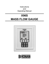
G11879b
A
B
G11879f
A
B
C
C
A Power supply B Inputs / outputs, communication C Signal cable (remote mount design only)
• Type of protection ATEX / IECEx: Increased safety
‘Ex e’
• Type of protection USA / Canada: ‘non IS’
• Maximum 250 Vrms
• Terminals: 1+, 2-, L, N,
• Type of protection ATEX / IECEx: Either increased
safety ‘Ex e’ or intrinsically safe ‘Ex ia’
• Type of protection USA / Canada: Either ‘non IS’ or
‘intrinsically safe IS’.
• When installing in ‘Ex ia’ or ‘IS’, suitable
intrinsically safe isolation amplifiers must be used
for the connection.
• Terminals: 31, 32, Uco, V1, V2, V3, V4, 41, 42, 51, 52
• Terminals: A, B, UFE, GRN
• Type of protection ATEX / IECEx: Increased safety
‘Ex e’
• Type of protection USA / Canada: ‘non IS’
Note
When installing in ‘Ex ia’ or ‘IS’ type of protection, the type of protection is determined by the type of electrical connection. The
information in Changing the type of protection on page 24 must be observed when changing the type of protection!

CoriolisMaster FCB400, FCH400 CORIOLIS MASS FLOWMETER | OI/FCB400/FCH400-EN REV. E 17
Zone 2, 21 and Division 2 – Model: FCx4xx-A2, FCx4xx-F2
Outputs on basic device Operating values (general) Type of protection – ‘nA’ / ‘NI’
U
N
I
N
U
N
I
N
Current / HART output 31 / U
CO
, active
Terminals 31 / U
CO
30 V 30 mA 30 V
30 mA
Current / HART output 31 / 32, passive
Terminals 31 / 32
30 V 30 mA 30 V
30 mA
Digital output 41 / 42, active*
Terminals 41 / 42 and V1 / V2*
30 V 30 mA 30 V
30 mA
Digital output 41 / 42, active**
Terminals 41 / 42 and U
CO
/ 32**
30 V 30 mA 30 V
30 mA
Digital output 41 / 42, passive
Terminals 41 / 42
30 V 25 mA 30 V
25 mA
Digital output 51 / 52, active*
Terminals 51 / 52 and V1 / V2*
30 V 30 mA 30 V
30 mA
Digital output 51 / 52, passive
Terminals 51 / 52
30 V 30 mA 30 V
30 mA
All outputs are electrically isolated from each other and from the power supply.
Digital outputs 41 / 42 and 51 / 52 are not electrically isolated from each other. Terminals 42 / 52 have the same potential.
* Only in conjunction with additional ‘24 V DC loop power supply (blue)’ plug-in card in slot OC1.
** Only in conjunction with current output U
CO
/ 32 in ‘Powermode’, see Current output Uco / 32 as loop power supply for digital output 41 / 42 or 51 / 52 on
page 50.
Inputs and outputs with optional plug-in cards Operating values (general) Type of protection – ‘nA’ / ‘NI’
U
N
I
N
U
N
I
N
Current output V3 / V4, active*
Terminals V3 / V4 and V1 / V2*
30 V 30 mA 30 V 30 mA
Current output V1 / V2, passive**
Current output V3 / V4, passive**
Terminals V1 / V2** or V3 / V4**
30 V 30 mA 30 V 30 mA
Digital output V3 / V4, active*
Terminals V3 / V4 and V1 / V2*
30 V 25 mA 30 V 25 mA
Digital output V1 / V2, passive**
Digital output V3 / V4, passive**
Terminals V1 / V2** or V3 / V4**
30 V 30 mA 30 V 30 mA
Digital input V3 / V4, active*
Terminals V3 / V4 and V1 / V2
30 V 3.45 mA 30 V 3.45 mA
Digital input V1 / V2, passive*
Digital input V3 / V4, passive*
Terminals V1 / V2** or V3 / V4**
30 V 3.45 mA 30 V 3.45 mA
Modbus® / PROFIBUS DP®
Terminals V1 / V2
30 V 30 mA 30 V 30 mA
* Only in conjunction with additional ‘24 V DC loop power supply (blue)’ plug-in card in slot OC1.
** The terminal assignment depends on the model number or the slot assignments. For connection examples, see Connection examples on page 53.

18 CoriolisMaster FCB400, FCH400 CORIOLIS MASS FLOWMETER | OI/FCB400/FCH400-EN REV. E
… 2 Use in potentially explosive atmospheres
… Electrical data
Zone 1 ,21 und Division 1 – Model: FCx4xx-A1, FCx4xx-F1
Type of protection ‘e’ / ‘XP’ ‘ia’ / ‘IS’
Outputs on basic device U
M
[V]
I
M
[A]
U
O
[V]
U
I
[V]
I
O
[mA]
I
I
[mA]
P
O
[mW]
P
I
[mW]
C
O
[nF]
C
I
[nF]
C
OPA
[nF]
C
IPA
[nF]
L
O
[mH]
L
I
[mH]
Current / HART output 31 / U
CO
, active
Terminals 31 / U
CO
30 0.2
30 30
115 115
815 815
10 10 5 5
0.08 0.08
Current / HART output 31 / 32, passive
Terminals 31 / 32
30 0.2
—
30
— 115
— 815
— 27 — 5
0.08 0.08
Digital output 41 / 42, active*
Terminals 41 / 42 and V1 / V2*
30 0.1
27.8 30
119 30
826 225
20 20 29 29
0.22 0.22
Digital output 41 / 42, active**
Terminals 41 / 42 and U
CO
/ 32**
30 0.1
30 30
115 115
826 225
16 16 10 10
0.08 0.08
Digital output 41 / 42, passive
Terminals 41 / 42
30 0.1
—
30
— 30
— 225
— 27 — 5
— 0.08
Digital output 51 / 52, active*
Terminals 51 / 52 and V1 / V2*
30 0.1
27.8 30
119 30
826 225
20 20 29 29
0.22 0.22
Digital output 51 / 52, passive
Terminals 51 / 52
30 0.1
—
30
— 30
— 225
— 27 — 5
— 0.08
All outputs are electrically isolated from each other and from the power supply.
Digital outputs 41 / 42 and 51 / 52 are not electrically isolated from each other. Terminals 42 / 52 have the same potential.
* Only in conjunction with additional ‘24 V DC loop power supply (blue)’ plug-in card in slot OC1.
** Only in conjunction with current output U
CO
/ 32 in ‘power mode’, see Current output Uco / 32 as loop power supply for digital output 41 / 42 or 51 / 52 on
page 50.
Type of protection ‘e’ / ‘XP’ ‘ia’ / ‘IS’
Inputs and outputs with optional plug-in cards U
M
[V]
I
M
[A]
U
O
[V]
U
I
[V]
I
O
[mA]
I
I
[mA]
P
O
[mW]
P
I
[mW]
C
O
[nF]
C
I
[nF]
C
OPA
[nF]
C
IPA
[nF]
L
O
[mH]
L
I
[mH]
Current output V3 / V4, active*
Terminals V3 / V4 and V1 / V2*
30 0.1 27.8 30 119 30 826 225 29 29 117 117 0.4 0.4
Current output V1 / V2, passive**
Current output V3 / V4, passive**
Terminals V1 / V2** or V3 / V4**
30 0.1 — 30
—
68 — 510 — 45 — 59
—
0.27
Digital output V3 / V4, active*
Terminals V3 / V4 and V1 / V2*
30 0.1 27.8 30 119 68 826 225 17 17 31 31 0.4 0.4
Digital output V1 / V2, passive**
Digital output V3 / V4, passive**
Terminals V1 / V2** or V3 / V4**
30 0.1 — 30
—
30 — 225 — 13 — 16
—
0.27
Digital input V3 / V4, active*
Terminals V3 / V4 and V1 / V2
30 0.1 27.8 30 119 3.45 826 25.8 17 17 31 31 0.4 0.4
Digital input V1 / V2, passive*
Digital input V3 / V4, passive*
Terminals V1 / V2** or V3 / V4**
30 0.1 — 30
—
3.45 — 25.8 — 13 — 16
—
0.27
Modbus® / PROFIBUS DP®
Terminals V1 / V2
30 0.1 4.2 4.2 150 150 150 150 1.5 1.5 6 6 0.14 0.14
* Only in conjunction with additional ‘24 V DC loop power supply (blue)’ plug-in card in slot OC1.
** The terminal assignment depends on the model number or the slot assignments. For connection examples, see Connection examples on page 53.
Change from one to tw o columns

CoriolisMaster FCB400, FCH400 CORIOLIS MASS FLOWMETER | OI/FCB400/FCH400-EN REV. E 19
… 2 Use in potentially explosive atmospheres
… Electrical data
Special connection conditions
Note
The AS plug-in card (24 V DC loop power supply) may only be
used to power the internal inputs and outputs on the device.
It must not be used to power external circuits!
Note
If the protective earth (PE) is connected in the flowmeter's
terminal box, you must ensure that no dangerous potential
difference can arise between the protective earth (PE) and the
potential equalization (PA) in areas with explosion risk.
Note
• For devices with a power supply of 11 to 30 V DC, on-site
external overvoltage protection must be provided.
• You must make sure that the overvoltage is limited to
140 % (= 42 V DC) of the maximum operating voltage.
The output circuits are designed so that they can be connected
to both intrinsically-safe and non-intrinsically-safe circuits.
• Combining intrinsically safe and non-intrinsically safe circuits
is not permitted.
• On intrinsically safe circuits, potential equalization should be
established along the entire length of the cable used for the
signal outputs.
• The rated voltage of the non-intrinsically safe circuits is
U
M
= 30 V.
• Intrinsic safety is preserved If the rated voltage U
M
= 30 V is
not up-scaled when connections are established to non-
intrinsically safe external circuits.
• The information in Changing the type of protection on
page 24 must be observed when changing the type of
protection.
Devices connected to the relevant equipment must not be
operated at over 250 V
rms
AC or 250 V DC to ground.
Installation in accordance with ATEX or IECEx must comply with
the applicable national and international standards and
directives.
Installation in the USA or Canada must comply with ANSI / ISA
RP 12.6, ‘Installation of intrinsically safe systems for hazardous
(classified) locations’, the ‘National Electrical Code (ANSI / NFPA
70), sections 504, 505’ and the ‘Canadian electrical code (C22.1-
02)’.
Apparatus connected to the flowmeter must have appropriate
explosion protection approval in accordance with the Entity
concept.
The apparatus must have intrinsically safe circuits.
The apparatus must be installed and connected in accordance
with the relevant manufacturer documentation.
The electrical specifications in Electrical data on page 16 must
be observed.

20 CoriolisMaster FCB400, FCH400 CORIOLIS MASS FLOWMETER | OI/FCB400/FCH400-EN REV. E
… 2 Use in potentially explosive atmospheres
Installation instructions
ATEX / IECEx
The installation, commissioning, maintenance and repair of
devices in potentially explosive atmospheres must only be
carried out by appropriately trained personnel. Works may be
carried out only by persons, whose training has included
instructions on different types of protection and installation
techniques, concerned rules and regulations as well as general
principles of zoning.
The person must possess the appropriate competences for the
type of work to be conducted.
The safety instructions for electrical apparatus in potentially
explosive areas must be in accordance with Directive
2014/34/EU (ATEX) and IEC 60079-14 (Installation of electrical
equipment in potentially explosive areas).
Comply with the applicable regulations for the protection of
employees to ensure safe operation.
cFMus
The installation, commissioning, maintenance and repair of
devices in areas with explosion hazard must only be carried out
by appropriately trained personnel.
The operator must strictly observe the applicable national
regulations with regard to installation, function tests, repairs,
and maintenance of electrical devices. (e. g. NEC, CEC).
Use in areas exposed to combustible dust
When using the device in areas exposed to combustible dusts
(dust ignition), the following points must be observed:
• The maximum surface temperature of the device may not
up-scale 85 °C (185 °F).
• The process temperature of the attached piping may up-
scale 85 °C (185 °F).
• Approved dust-proof cable glands must be used when
operating in Zone 21, 22 or in Class II, Class III.
Opening and closing the housing
DANGER
Danger of explosion if the device is operated with the
transmitter housing or terminal box open!
While using the device in potentially explosive atmospheres
before opening the transmitter housing or the terminal box,
note the following points:
• A valid fire permit must be present.
• Make sure that no flammable or hazardous atmospheres
are present.
WARNING
Risk of injury due to live parts!
When the housing is open, contact protection is not provided
and EMC protection is limited.
• Before opening the housing, switch off the power supply.
See also Opening and closing the housing on page 38.
Only original spare parts must be used to seal the housing.
Note
Spare parts can be ordered from ABB Service.
www.abb.com/contacts
/