Page is loading ...

©Hubbell Incorporated | hpsliteratur[email protected]om | hubbellpowersystems.com
Rev. A - 02/2021
TYPE
AVR/AVRV
Counterbalance
Adjustment &
Installation Guide

2
©Hubbell Incorporated | hpsliteratur[email protected]om | hubbellpowersystems.com
1. Introduction
Table of Contents
The AVR counterbalance assembly is designed for multiple configurations to accommodate varying
loads associated with interrupting attachments and switch mounting configurations. The assembly
has been adjusted at the factory for the application specified on the customers purchase order at the
time of shipment.
Field modifications are typically limited to adjusting pre-load; however, if the switch application
changes after shipment, the counterbalance configuration may require spring exchange or installation.
NOTE: These configurations may or may not be readily apparent. Depending upon the application,
the switch may include counterbalance assemblies on one or both sides of the switch phase. The
assembly will also include springs with diering load characteristics dictated by the application.
Consult the factory to determine the proper configuration for the switch application.
1. Introduction 2
2. Component Identification 3
3. Counterbalance Adjustment 4
3.1 Horizontal Configuration 4
3.2 Vertical Configuration 6
3.3 Spring Loading Guide 7
4. Counterbalance Installation 8
PAGE NO.

3
©Hubbell Incorporated | hpsliteratur[email protected]om | hubbellpowersystems.com
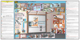
2. Component Identification
Figure 1. AVR Live Part Components
Figure 2. AVR Counterbalance Assembly Components

4
©Hubbell Incorporated | hpsliteratur[email protected]om | hubbellpowersystems.com
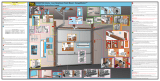
3. Counterbalance Adjustment
3.1 Horizontal Configuration
If the switch has the correct counterbalance
configuration for the switch application,
adjustments can be made to either add
additional pre-load or remove pre-load from
the counterbalance springs.
Each counterbalance spring that is installed
in the factory will have a yellow paint stripe
on both the Cover and the Adjustment Plate
denoting the initial installation setting.
The following tools will be required:
• 1-5/8” wrench
• Rubber mallet
For HORIZONTALLY mounted units the spring loads as the blade closes so always adjust in the
OPEN POSITION.
The following steps must be followed for adjustment:
1. Check the switch is in OPEN position.
2. Grip the end of the Adjustment Plate using a 1-5/8” wrench.
3. Depress the Spring and Adjustment Plate by striking the end of the Adjustment Plate with the rubber
mallet until the Adjustment Plate is no longer sitting in the tabs of the Cover. Rotate the Adjustment
Plate with the wrench to the next position.
NOTE: See Section 3.3, Table 1 for allowable preload notches for each spring.
Figure 3. AVR Counterbalance
initial installation mark

5
©Hubbell Incorporated | hpsliteratur[email protected]om | hubbellpowersystems.com
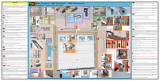
INCREASE load by rotating toward the hinge.
Viewing the phase from the hinge end, increase
the load on the right counterbalance spring by
rotating the Adjustment Plate counterclockwise
(Figure 5). Increase the load on the left
counterbalance spring by rotating the Adjustment
Plate clockwise (Figure 6).
DECREASE load by rotating toward the jaw.
Viewing the phase from the hinge end, decrease
the load on the right counterbalance spring by
rotating the Adjustment Plate clockwise (Figure
7). Decrease the load on the left counterbalance
spring by rotating the Adjustment Plate
counterclockwise (Figure 8).
Figure 5. Increase the Load on Right
Counterbalance Spring, Horizontal Orientation
Figure 6. Increase the Load on Left
Counterbalance Spring, Horizontal Orientation
Figure 7. Decrease the Load on Right
Counterbalance Spring, Horizontal Orientation
Figure 8. Decrease the Load on Left
Counterbalance Spring, Horizontal Orientation

6
©Hubbell Incorporated | hpsliteratur[email protected]om | hubbellpowersystems.com
3.2 Vertical Configuration
For VERTICALLY mounted units the spring loads as the blade opens so always adjust in the
CLOSED POSITION.
The following steps must be followed for adjustment:
1. Check the switch is in CLOSED position.
2. Grip the end of the Adjustment Plate using a 1-5/8” wrench.
3. Depress the Spring and Adjustment Plate by striking the end of the Adjustment Plate with the rubber
mallet until the Adjustment Plate is no longer sitting in the tabs of the Cover. Rotate the Adjustment
Plate with the wrench to the next position.
NOTE: See Section 3.3, Table 1 for allowable preload notches for each spring.
INCREASE load by rotating toward the jaw. Viewing the phase from the hinge end, increase the load on
the right counterbalance spring by rotating the Adjustment Plate clockwise (Figure 9). Increase the load
on the left counterbalance spring by rotating the Adjustment Plate counterclockwise (Figure 10).
Figure 10. Increase Load on Left
Counterbalance Spring, Vertical Orientation
Figure 9. Increase the Load on Right
Counterbalance Spring, Vertical Orientation

7
©Hubbell Incorporated | hpsliteratur[email protected]om | hubbellpowersystems.com
Figure 11. Decrease Load on Right
Counterbalance Spring, Vertical Orientation
Figure 12. Decrease Load on Left
Counterbalance Spring, Vertical Orientation
3.3 Spring Loading Guide
Adjustment notches occur every 18° and the counterbalance assemblies are limited to a maximum of 2 or 3
notches of preload. Table 1 provides the maximum preload notches for each spring.
Spring Part Number Spring Color
Additional Torque per
Notch (in-lbs)
Maximum Preload
(Notches)
R90001033 Black 48.6 3
R90001037 White 48.6 3
R90001034 Red 102.4 2
R90001038 Green 102.4 2
R90001035 Yellow 207.6 2
R90001039 Orange 207.6 2
DECREASE load by rotating toward the hinge. Viewing the phase from the hinge end, decrease the load on
the right counterbalance spring by rotating the Adjustment Plate counterclockwise (Figure 11). Decrease
the load on the left counterbalance spring by rotating the Adjustment Plate clockwise (Figure 12).
Table 1. AVR Counterbalance Spring Preload

8
©Hubbell Incorporated | hpsliteratur[email protected]om | hubbellpowersystems.com
If the application of a switch changes, the switch may require existing counterbalance assemblies to be
exchanged or new counterbalance assemblies to be added. Consult the factory to determine the correct
counterbalance configuration.
The following tools will be required:
• 1/8” allen wrench
• 3/4” wrench
• 1-5/8” wrench
• Channellock pliers
• Rubber mallet
The following steps must be followed for adjustment:
1. Determine the installation orientation of the unit.
• Horizontally mounted: The switch phase must be open during the installation of the spring.
• Vertically mounted: The switch phase must be closed during the installation of the spring.
2. Locate the two 1/4” set screws on the top of the AVR hinge casting (Figure 13). Using the 1/8” allen
wrench, remove both set screws and set aside.
3. Remove the hinge pin by turning counterclockwise by hand or using the Channellock pliers.
NOTE: Between the Support Casting and the Hinge Casting, a stainless steel 5/8” flat washer is
installed to prevent galling during operation. Take care not to lose the washer upon removing the
hinge pin.
4. Counterbalance Installation
Figure 13. Remove set screws from Hinge Casting

9
©Hubbell Incorporated | hpsliteratur[email protected]om | hubbellpowersystems.com
4. Install the new hinge pin and backup plate casting (Figure 14) required for the counterbalance
assembly by threading the hinge pin in by hand or with the adjustable wrench. The grooves of the
backup plate should fit over the blade support casting.
CAUTION: To prevent the hinge pin from pinching the blade support castings, tighten the hinge pin
until the outer 1/2” stainless steel flat washer can no longer spin freely, and then loosen the hinge
pin by 1/4 of a turn.
5. Install 1/4” set screws in the hinge casting that were previously removed in Step 2. Install the first until it
tightens against the hinge pin. Then install the second set screw to ensure the first remains locked into
position.
CAUTION: Failure to re-install set screws could cause the hinge pins to tighten with repeated
operation of the switch and prevent the switch from operating correctly.
Figure 14. Backup Plate and Hinge pin installation
Figure 15. Hinge pin installed

10
©Hubbell Incorporated | hpsliteratur[email protected]om | hubbellpowersystems.com
6. Slide the spring over the Backup Plate and Hinge Pin. Align the spring with the three tabs on the
Backup Plate.
NOTE: The hook of the spring must go over the large tab on the Backup Plate (Figure 17).
7. Slide the Adjustment Plate over the Hinge Pin and spring. Align the three tabs on the Adjustment Plate
with the spring (Figure 18).
NOTE: The hook of the spring must go over the large tab on the Adjustment Plate.
Figure 16. Spring Installation
Figure 17. Spring hook installation

11
©Hubbell Incorporated | hpsliteratur[email protected]om | hubbellpowersystems.com
8. Slide the Cover over the assembly, aligning the first two holes on the mounting tab to the threaded
holes in the Hinge (Figure 19).
9. Check to ensure the Adjustment Plate is seated on the tabs inside the Cover. The visible face of the
Adjustment Plate will be flush against the Cover.
10. Assemble the counterbalance assembly Cover to the Hinge Casting using two 1/2”-13 x 1” stainless
steel bolts and 1/2” stainless steel lock washers. Slight compression of the spring will be required.
Figure 19. Spring Cover Installation
Figure 18. Spring alignment in Cover

©2021 Hubbell Incorporated.
Because Hubbell has a policy of continuous product improvement,
we reserve the right to change design and specifications without notice.
Printed in the U.S.A. | TD_10_309_E
For product inquiries, please contact your local sales
representative or customer service representative.
hubbellpowersystems.com
Rev. A - 02/2021
11. Mark the initial installation point of the Adjustment Plate by putting a mark across the Adjustment
Plate and Cover (Figure 21).
12. Repeat steps for opposite side, if required.
13. Confirm operation of switch. If additional pre-load is required on the counterbalance spring, see
Section 2: Counterbalance Adjustment.
Figure 20. Counterbalance Assembly installation
Figure 21. AVR Counterbalance initial installation mark
/