Page is loading ...

Milestone AV Technologies
6436 City West Parkway
Eden Prairie, MN 55344 USA
Customer Service
Americas: 800-359-5520 • 651-484-7988 • inf[email protected]
Europe, Middle East, and Africa: +31 (0) 495 580 852 • europe.sanus@milestone.com
Asia Pacifi c: 86 755 8996 9226 • [email protected]
accents.sanus.com
©2012 Milestone AV Technologies, a Duchossois Group Company.
All rights reserved. Accents is a Milestone brand.
All other brand names or marks are used for identifi cation purposes and are trademarks of their respective owners.
SAN25BB Instruction Manual
(6904-002022 <01>)
Scan here to view
product demo and install
videos or visit san.us/109

6904-002022 <01>
2
ඔ
෫
ୗᆒᚓኞไ
ᡈ
⪅ἥ㟢孠
ᮘᐦ▱孮孮孮凞ᮏ ໟྵⓗ ಙᜥᅾᮍ⚦⚦ ⚦⚦ ⚦
ᮏ ᡤໟྵⓗಙᜥ ᆒ⣔
⚦⚦
⚦⚦
10°
5°
1.90
48.4
IMPORTANT SAFETY INSTRUCTIONS – SAVE THESE INSTRUCTIONS – PLEASE READ ENTIRE MANUAL PRIOR TO USE
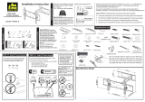
Speci cations
Ù Weight capacity-DO NOT EXCEED: 36.2 kg (80 lb) includes TV and any accessories
Ù Tilt: +5° -10°
CAUTION: Avoid potential personal injuries and property damage!
Ù Do not use this product for any purpose not explicitly speci ed by manufacturer.
Ù The wall must be capable of supporting ve times the weight of the monitor and mount combined.
Ù This product is not designed for use in metal stud walls!
Ù If you do not und
erstand these instructions, or have doubts about the safety of the installation, assembly or use of this
product, contact Customer Service or call a quali ed contractor.
Ù Manufacturer is not responsible for damage or injury caused by incorrect assembly or use.
Technical Speci cations
in.
mm
Required Tools
10mm
(3/8 in.)
5.5mm
(7/32 in.)
13mm
(1/2 in.)
ඔ ෫ୗᆒᚓኞไᡈ⪅ἥ㟢孠
ᮘᐦ▱
孮孮
孮凞
ᮏ
ໟྵⓗ ಙᜥᅾᮍ⚦⚦ ⚦⚦ ⚦
ᮏ ᡤໟྵⓗಙᜥ ᆒ⣔⚦⚦ ⚦⚦
UP TO
15.75
400.0
16.93
430.0
405.0
15.94
152.4
6.00
95.3
3.75
120.7
4.75
15.50
393.7

6904-002022 <01>
3
⁄ x 2¾ in. ⁄ in.
WARNING: This product contains small items that could be a choking hazard if swallowed.
Before starting assembly, verify all parts are included and undamaged. If any parts are missing or damaged, do not return the
damaged item to your dealer; contact Customer Service. Never use damaged parts!
NOTE: M4, M6, or M8 describes the diameter, mm describes the length of screws that are labeled M# X ##mm. Not all
hardwar
e included will be used.
[01] x 1
[02] x 1
[03] x 1
[04] x 3
[05] x 3 [06] x 3
[07] x 4 [08] x 4
[09] x 4
[10] x 4 [11] x 4
[12] x 4 [13] x 4
[14] x 4
[15] x 4
[16] x 4
Supplied Parts and Hardware
M6 x 12mm M6 x 20mm M6 x 35mm
M4 x 35mm
M4 x 12mm
M4 M6/M8
M8 x 16mm M8 x 35mm

6904-002022 <01>
4
M4/M6/M8
1-2 Attach brackets to a TV with a at back
[07, 09, 10, 12]
[02, 03]
[14, 15]
Ensure the brackets are level on the back of the TV.
If you require additional space for cables, recesses, or
protrusions, choose con guration B.
[03]
[02]
Your TV type will help you determine which hardware
con guration to use.
A. Installation option without spacers (TVs with at backs)
B. Installation option using spacers (TVs with irregular
backs)
Hand thread screws into the threaded inserts on the back of
your TV to determine the correct screw diameter (M4, M6, or
M8).
CAUTION: Avoid potential personal injuries and
property damage! Verify that there are adequate threads
to secure the brackets to the monitor. If you encounter
resistance, stop immediately and contact customer
service. Use the shortest screw and spacer combination to
accommodate your needs. Using hardware
that is too long
may damage your TV.
B
1-1 Select the hardware diameter and length
A
1 Select TV Hardware and Mount TV Brackets
A

6904-002022 <01>
5
M4/M6/M8
1-2 Attach brackets to a TV with an irregular back
1-3 Adjust straps
[08, 11, 13]
[02, 03]
[14, 15]
Ensure the bracket is level on the back of the TV.
Standard con gurations are shown.
For special applications, or if you are uncertain about your
hardware selection, contact Customer Service.
[03]
[03]
[16]
[02]
[02]
For ease of access, straps should be level with the bottom of the TV.
B

6904-002022 <01>
6
[01]
[01]
< 16 mm
(5/8 in.)
2 Mount the Wall Plate
Wood stud
2-1 Locate stud
2-2 Mark the wall
Level the wall plate [01] and mark the hole locations.
2-3 Drill pilot holes
2-4 Tighten lag bolts [04]
CAUTION:
Avoid potential injuries or property damage!
Improper use could reduce the holding power of the lag bolt. To
avoid potential injuries or property damage
Ù DO NOT over-tighten the lag bolts [04].
Ù Tighten the lag bolts [04] only until the washe
rs [06] are
pulled rmly against the wall plate [01].
[04]
[06]
Verify the center of the stud using an awl, a thin nail, or an
edge to edge stud nder.
CAUTION: Avoid potential personal injuries and property
damage!
Ù Any material covering the wall must not exceed 16 mm
(5/8 in.).
Ù Minimum wood stud size: common 51 x 102 mm (2 x 4 in.)
(nominal 38 x 89 mm (1½ x 3½ in.)).
CAUTION:
Avoid potential injuries or property damage! Pilot
holes MUST be drilled to a depth of 75 mm (3 in.), using a 5.5 mm (⁄
in.) diameter drill bit.
75 mm
(3 in.)
5.5 mm
(7/32 in.)
13 mm
(1/2 in.)

6904-002022 <01>
7
2-1 Level wall plate [01] and mark hole locations
2 Mount the Wall Plate
Solid Concrete and Concrete Block
2-2
Drill pilot holes as illustrated
2-3 Insert anchors [05]
2-4 Tighten lag bolts [04]
CAUTION: Avoid potential personal injuries and property
damage!
Ù Mount the wall plate [01] directly onto the concrete surface.
Ù Minimum solid concrete thickness: 203 mm (8 in.).
Ù Minimum concrete block size: 203 x 203 x 406 mm (8 x 8 x 16 in.).
Ù Minimum space between top two fasteners: 120.7 mm (4¾ in.
).
CAUTION: To avoid potential injuries or property damage:
Ù Pilot holes MUST be drilled to a depth of 75 mm (3 in.) using a
10 mm (3/8 in.) diameter drill bit.
Ù Never drill into the mortar between blocks.
CAUTION: To avoid potential injuries or property damage:
Be sure the anchors [05] are seated ush with the concrete surface.
[01]
[05]
[05]
[01]
[04]
[06]
Tighten lag bolts [04] only until the washers [06] are pulled rmly
against the wall plate [01].
CAUTION: Improper use could reduce the holding power of
the lag bolt. To avoid potential injuries or property damage: DO NOT
over-tighten the lag bolts [04].
75 mm
(3 in.)
10 mm
(3/8 in.)
13 mm
(1/2in.)

6904-002022 <01>
8
[02, 03]
[02, 03]
[01]
[01]
3 Hang the TV onto the Wall Plate
1 2
HEAVY! You will need
assistance with this step.
There is an audible click when the brackets
[02, 03] are securely latched to the wall
plate [01].

6904-002022 <01>
9
4 Adjust Tilt and Level
10°
5°
Loosen the knobs on the TV brackets
[02, 03] to adjust the tilt of your TV.
Tighten the knobs when your TV is set
to the desired tilt.
If needed, tighten a screw on the TV brackets [02, 03] to level the TV.
[02, 03]
[03]
[02]

6904-002022 <01>
10
Milestone AV Technologies and its a liated corporations and subsidiaries (collectively, “Milestone”), intend to make this manual accurate and complete. However, Milestone makes no claim that the information
contained herein covers all details, conditions, or variations. Nor does it provide for every possible contingency in connection with the installation or u
se of this product. The information contained in this
document is subject to change without notice or obligation of any kind. Milestone makes no representation of warranty, expressed or implied, regarding the information contained herein. Milestone assumes no
responsibility for accuracy, completeness or su ciency of the information contained in this document.
To remove the TV from the wall plate, simultaneously pull
release cords down and TV out, and then lift the TV up and out
away from the wall.
HEAVY! You will need assistance with this step.
Maintenance - Removing the TV from the Wall Plate
/