Page is loading ...

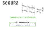
QSF
207
INSTRUCTION MANUAL
We’ll Make It Stress-Free
If you have any questions along the way, just give us a call.
1-800-359-5520 We’re ready to help!
Scan for easy install video
san.us/1143

2
CAUTION: IMPORTANT SAFETY INSTRUCTIONS — PLEASE READ ENTIRE MANUAL PRIOR TO USE — SAVE THESE INSTRUCTIONS
No? Perfect – you may continue.
Yes? This mount is NOT compatible.
Visit secura-av.com or call 1-800-359-5520
(UK: 0800 056 2853) to fi nd a compatible mount.
Please read through these instructions completely to be sure you’re comfortable with this easy install process.
Also check your TV owner’s manual to see if there are any special requirements for mounting your TV.
If you do not understand these instructions or have doubts about the safety of the installation, assembly or use
of this product, contact Customer Service at
1-800-359-5520 (UK: 0800 056 2853).
Do you have
all the tools
needed?
1
2
3
4
What is your
wall made of?
Ready to begin?
CAUTION:
DO NOT exceed the maximum
weight indicated
. This mounting system is intended for
use only with the maximum weights indicated. Use with
products heavier than the maximum weights indicated
may result in collapse of the mount and its accessories,
causing possible injury.
25 lbs.
(11.3 kg)
Does your TV
(including accessories)
weigh MORE than
25 lbs. (11.3 kg)?
CAUTION: Avoid potential personal injury or property damage!
● This product is designed for use in wood stud, steel stud, solid concrete, and concrete block walls -
DO NOT install into drywall alone
● The wall must be capable of supporting fi ve times the weight of the TV and mount combined
● Do not use this product for any purpose not explicitly specifi ed by manufacturer
● Manufacturer is not responsible for damage or injury caused by incorrect assembly or use
Wood Stud Install
Concrete Install
Steel Stud Install
Tape
Measure
Pencil Level
Screw
driver
Electric
Drill
Socket
Wrench
Stud
Finder
Awl
Wood
Drill Bit
Masonry
Drill Bit
Hammer
Steel
Drill Bit
3/8 in.
(10 mm)
7/32 in.
(5.5 mm)
1/2 in.
(13 mm)
1/2 in.
(13 mm)
Before getting started, let’s make sure this mount is perfect for you!
Solid concrete or
concrete block?
Perfect!
Drywall with
wood studs?
Perfect!
CAUTION:
DO NOT install into
drywall alone
Unsure?
Call Customer Service: 1-800-359-5520 (UK: 0800 056 2853)
?
Drywall
with
steel studs?
Steel stud kit required (NOT INCLUDED)

3
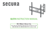
TV INTERFACE
WALL PLATE
FULLY ASSEMBLED MOUNT
TOP VIEW - EXTENDED
TOP VIEW - RETRACTED
SIDE VIEW - EXTENDED
SIDE VIEW - RETRACTED
3-D
3.94in
100mm
7.87in
200mm
7.87in
200mm
.35in
8.8mm
.33in
8.4mm
2.56in
65mm
7.19in
182.6mm
1.14in
29.1mm
4.90in
124.5mm
8.80in
223.6mm
8.80in
223.6mm
10.26in
260.5mm
ESTIMATED 32" TV
30deg 30deg
4.27in
108.6mm
9.96in
252.9mm
7.59in
192.7mm
3.31in
84.1mm
Dimension Specifications
NOTE: TV shifts 4.27 in. (108.6 mm) to
the right or left when in the home position.
Consider this when selecting the location of
your wall mount.

4
M4 x 8mm
22mm
M4
M6/M8
M8 x 16mm M8 x 35mm
M8 x 20mm
M6 x 12mm
M6 x 35mm
M4 x 35mm
STEP 1 Parts and Hardware
TV Bracket
TV Screws
TV Bracket
Extenders
Interface Screws
(TV Bracket Extenders)
Parts and Hardware
Washers
Spacers
03 x8
05 x4
06 x4 07 x4
11 x4 12 x4 13 x4
08 x4
09 x4
10 x4
01 x1
02 x4
M4
x 8
mm
M8
x
1
6m
M6 x
1
2
m
m
terface
S
crews
Bracket Extender
s)
0303 x
8
0
5
0
5
x4
0606
x4
WARNING: This product contains small items that could be a choking hazard if swallowed.
Before starting assembly, verify all parts are included and undamaged. If any parts are missing or damaged, do not return
the damaged item to your dealer; contact Customer Service. Never use damaged parts!
NOTE: Not all hardware included will be used.

5
STEP 2 Parts and Hardware
Wall Plate Assembly
14 x1
Lag Bolts
15 x2
16 x2
5/16 x 2¾ in.
Fischer UX 10 x 60R
Concrete Anchors
For concrete installations ONLY
CAUTION: Do not use in drywall or wood
Washers
5/16 in.
17
x2

6
8-32 x 3/8 in.
STEP 3 Hardware
Hardware to Manage Cables
Securement Screw
18 x1
8-32
Securement Washer
19 x1
Cable Ties
20 x3

7
1/4-20 Snap Toggle BB
S1 x2
S2 x2
S3 x2
Hardware for STEP 2C Steel Stud Installations Only
[NOT INCLUDED]
Contact Customer Service at 1-800-359-5520 (UK: 0800 056 2853)
to have these additional pieces shipped directly to you.
Anchors
Washers
.734 x .312 x .065 in
Screws
1/4-20 x 1.75

8
A
x
8mm
STEP 1 Attach TV Bracket to TV
These smaller hole patterns ONLY use TV bracket
01
.
Do not use the four TV bracket extenders
02
and eight screws
03
.
7.5 x 7.5
10.0 x 10.0
01
10.0
10.0
7.5
1-1 Measure Your TV Hole Pattern 1-2 Assemble Your TV Bracket
Determine which TV bracket configuration to use, A, B, or C
based on your TV hole pattern measurements.
TV hole pattern
measurement
cm
inches
02
03
Measure the width and height of your TV hole
pattern in cm (see conversion chart below).
Record your measurements:
Width ____cm x Height ____cm
7.5
Dimensions in cm
inch dimensions are approximate
inches cm mm
3 7.5 75
4 10 100
7 ⅞ 20 200
W
H

9
C
TV hole pattern
measurement
B
TV hole pattern
measurement
Assemble TV bracket extenders
02
onto TV bracket
01
as illustrated.
Secure using eight screws
03
in the corner holes shown.
Dimensions in cm Dimensions in cm
20.0 x 20.0
01
20.0
20.0
02
02
02
02
03
Assemble TV bracket extenders
02
onto TV bracket
01
as illustrated.
Secure using eight screws
03
in the corner holes shown.
20.0 x 10.0
20.0
10.0
01
02
02
02
02
03

10
1-3 Select TV Screw
Diameter
1-4 Select TV Screw Length
Too Short
Too Long
CAUTION:
Verify adequate thread
engagement with your screw/
washer/spacer combination
AND TV bracket (STEP 1-5).
- Too short will not hold the TV.
- Too long will damage the TV.
Correct
Standard configurations
are shown. For special
applications, or if you
are uncertain about your
hardware selection,
contact Customer Service
at 1-800-359-5520.
M6 M8
FLAT BACK ROUND BACK CABLESINSET HOLES
M4
If your TV has a flat back AND you want your TV closer to the
wall, use the shorter TV screws and no spacers
13
.
Spacers
13
and longer TV screws are supplied to accommodate:
● Round/irregular back TVs
● TVs with inset mounting holes
● Extra space needed for cables
Hand thread screws into
the threaded inserts on
the back of your TV to
determine which screw
diameter (
M4, M6, or M8)
to use.
13

11
Flat Back
1-5 Attach TV Bracket
TV Bracket
Confi guration A
Illustrated
(with spacers)
TOP OF TV
TOP OF TV
TV Bracket
Confi guration B
Illustrated
(with spacers)
NOTE: For 20.0 x 20.0 or 20.0 x 10.0 hole
patterns, you may need to loosen the screws
03
to align the bracket extenders
02
.
After bracket extenders
02
are secured to
the back of your TV, re-tighten screws
03
.
02
01
01
Round Back / Extra Space
04
13
11 12
08 09 10
11 12
05 06 07
Position your TV bracket configuration (A, B, or C)
over your TV hole pattern - making sure the bracket is centered over the TV hole pattern and level.
Install using the TV screw/washer/spacer configuration you selected for your TV.
CAUTION: Avoid potential personal injuries and property damage! DO NOT use power tools for this step. Tighten the screws only enough
to secure the TV bracket to the TV. DO NOT overtighten the screws.
IMPORTANT: Ensure TV bracket is securely fastened before moving on to the next step.

12
2 3
14
1
NOTE: TV shifts
4.27 in. (108.6 mm)
to the right or left
when in the home
position. Consider
this when select-
ing the location of
your wall mount.
STEP 2A Attach Wall Plate to Wall
Wood Stud Installation
Max. 5/8 in.
(16 mm)
7/32 in.
(5.5 mm)
2 ¾ in. (70 mm)
1. Locate your stud. Verify and mark the center of the stud by finding the stud edges using an awl, a thin nail, or an edge to
edge stud finder.
2. Position the wall plate
14
at your desired height and line up the holes with your stud center line. Level the wall plate
14
and
mark the hole locations.
3. Drill pilot holes using a 7/32 in. (5.5 mm) diameter drill bit.
IMPORTANT: Pilot holes must be drilled to a depth of 2 ¾ in. (70 mm). Be sure to drill into the center of the stud.
CAUTION: Avoid potential personal injury or property damage!
● Drywall covering the wall, must not exceed 5/8 in. (16 mm)
● Minimum wood stud size: common 2 x 4 in. (51 x 102 mm) nominal 1½ x 3½ in. (38 x 89 mm)
● Stud center must be verified

13
15
14
14
4
15
16
a
a
4. Install wall plate assembly
14
using two lag bolts
15
and washers
16
. Tighten the lag bolts only until the washers are
pulled firmly against the wall plate.
NOTE: If needed, you can make small level adjustments to the wall plate by loosening the bottom lag bolt
15
and shifting
the wall plate until level. Tighten the bottom lag bolt when adjustments are complete.
CAUTION: Avoid potential personal injury or property damage! Both lag bolts
15
MUST BE firmly tightened to
prevent unwanted movement of the wall plate
14
.
Ensure the wall plate is securely fastened to the wall before continuing
on to the next step.
Go to STEP 3 on PAGE 20.

14
1. Position the wall plate
14
on the wall at your desired height. Level the wall plate
14
and mark the hole locations.
2. Drill two pilot holes using a 3/8 in. (10 mm) diameter masonry drill bit.
IMPORTANT: Pilot holes must be drilled to a depth of 3 in. (75 mm). Never drill into the mortar between blocks.
14
21
NOTE: TV shifts 4.27 in. (108.6 mm)
to the right or left when in the home
position. Consider this when selecting
the location of your wall mount.
3/8 in.
(10 mm)
3 in. (75 mm)
STEP 2B
Attach Wall Plate to Wall
Solid Concrete or Concrete Block
Installation
CAUTION: Avoid potential personal injury or property damage!
● Mount the wall plate assembly
14
directly onto the concrete surface.
● Minimum solid concrete thickness: 8 in. (203 mm)
● Minimum concrete block size: 8 x 8 x 16 in. (203 x 203 x 406 mm)

15
43
3. Insert two anchors
17
.
CAUTION: Be sure the anchors are seated flush with the concrete surface.
4. Install wall plate assembly
14
using two lag bolts
15
and washers
16
. Tighten the lag bolts only until the washers are
pulled firmly against the wall plate.
CAUTION: Improper use could reduce the holding power of the lag bolt
15
. DO NOT over-tighten the lag bolts.
NOTE: If needed, you can make small level adjustments to the wall plate by loosening the bottom lag bolt
15
and shifting the
wall plate until level. Tighten the bottom lag bolt when adjustments are complete (see page 13).
Go to STEP 3 on PAGE 20.
14
15
17
16

16
● Studs must be at least 2x 4 in. / 25 ga.
● Stud type and structural strength must
conform to the North American Specification
for the Design of Cold-Formed Steel
Structural Members
[362 S 125 18, C-Shape, S - Stud Section].
● If back side of wall is unfinished, drywall must be
installed to a minimum of one stud left and right
of the stud(s) being used to install the mount.
● Drywall must be a minimum of 1/2 in. (13 mm)
thick on each side of the studs, and a minimum
clearance of 1⅞ in. (48 mm)
behind the wall is required.
● Drywall must be secured to studs with
screws 12 in. (304.8 mm) on center.
● This product must be centered on the studs.
Min.
1/2 in.
(13 mm)
1
2
1. Locate your stud. Verify and mark the center of the stud by finding the stud
edges using an awl, a thin nail, or an edge to edge stud finder.
2. Level the mount and mark the hole locations.
Steel Stud Anchor Kit SSMK1 is not included
(see page 7) Contact
Customer Service at 1-800-359-5520 to have the additional hardware
shipped directly to you.
NOTE: TV shifts 4.27
in. (108.6 mm) to the
right or left when in
the home position.
Consider this when
selecting the location
of your wall mount.
CAUTION:
Avoid potential personal
injury or property damage!
STEP 2C
Attach Wall Plate to Wall
Steel Stud Installation

17
3
4
3. Drill pilot holes as illustrated.
4. Fold metal channel of anchor
S1
until it is flat with the plastic straps and slide the metal channel into the drilled hole.
1 in. (25 mm)
1/2 in.
(13 mm)
S1

18
5
6
5. Hold the plastic straps of anchor
S1
by the end and pull towards you until the metal channel is flush behind the drywall.
6. Slide the plastic cap down the straps and into the hole with the lip of the cap flush against the wall.
S1
S1

19
7
8
7. Bend the straps up and down until they snap off level with the lip of the cap.
CAUTION: Be sure the cap
is seated against the drywall surface and the ends of the anchor do not extend beyond the
cap - cut if neccessary.
8. Install wall plate assembly
14
using two screws
S2
and two washers
S3
. Tighten the screws only until they are pulled
firmly against the wall plate.
NOTE: If needed, you can make small level
adjustments to the wall plate by loosening the bottom lag
bolt
S2
and shifting the wall plate until level. Tighten the
bottom lag bolt when adjustments are complete.
CAUTION:
Avoid potential personal injury or property
damage! All screws
S2
MUST BE firmly tightened to
prevent unwanted movement of the wall plate
14
.
Ensure
the wall plate is securely fastened to the wall before
continuing on to the next step.
S1
S3
S2
S1
14

20
HEAVY! You may need assistance with this step.
STEP 3 Hang TV onto Wall Plate
1. Hang the TV onto the arm of wall plate assembly
14
by first hooking the top support, then resting the TV into place.
2. Lock the TV to the wall plate assembly
14
with securement screw
18
and washer
19
.
CAUTION: Avoid potential personal injury or property damage! This securement screw
18
must be installed to secure
the TV onto the wall plate assembly
14
.
14
14
44
1 2
18
19
/