Page is loading ...

Sanus Systems
2221 Hwy 36 West
Saint Paul, MN 55113 USA
Customer Service
Americas: 800-359-5520 • 651-484-7988 • [email protected]
Europe, Middle East, and Africa: + 31 40 2324700 • europe.sanus@milestone.com
Asia Pacifi c: 86 755 8996 9226 • [email protected]om
accents.sanus.com
©2010 Milestone AV Technologies, a Duchossois Group Company.
All rights reserved. Accents is a Milestone brand.
All other brand names or marks are used for identifi cation purposes and are trademarks of their respective owners.
A701
(6904-002018 <00>)
3 mm
(1/8 in.)
Wood Stud
12 mm
(7/16 in.)
6 mm
(15/64 in.)
2.4 mm
(3/32 in.)

6904-002018 <00>
2
1
2
3
1
2
3
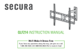
Thank you for purchasing the ELM701 anti-tip strap. Installing this product is as easy as 1 - 2 - 3!
1. Attach to the TV.
2. Attach to the furniture.
3. Optional - Attach to the wall.
See manual for more detailed instructions.
IMPORTANT SAFETY INSTRUCTIONS - SAVE THESE INSTRUCTIONS - PLEASE READ ENTIRE MANUAL BEFORE USING THIS PRODUCT

6904-002018 <00>
3
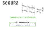
Wood stud walls
Tools required
CAUTION / WARNING Loosen/Tighten Heavy! Assistance Required.
WARNING: This product contains small items that could be a
choking hazard.
CAUTION: Avoid potential personal injuries and property damage!
Do not use this product for any purpose not explicitly speci ed by manufacturer.
This product is designed for use in wood frame walls only!
If you do not understand these instructions, or have doubts about the safety of the installation, assembly or use of this product, contact manufacturer
Customer Service or call a quali ed contractor.
Manufacturer is not responsible for damage or injury caused by incorrect assembly or use.
CAUTION:

6904-002018 <00>
4
Supplied Parts and Hardware
Before starting assembly, verify all parts are included and undamaged. If any parts are missing or damaged, do not return the damaged item to your dealer; contact Customer
Service. Never use damaged parts!
NOTE:
Not all hardware included will be used.
M8 x 40mm
M4 x 30mm
M6 x 35mm
M5 x 30mm
M4 / M5
M6 / M8
M4 / M5
M6 / M8
1/4 x 2.0 in.
1/4 in.
#10 x 1 in.
1/4-20
1/4-20
[08] x 2 [09] x 2
[10] x 2 [11] x 2
[12] x 2 [13] x 2 [14] x 2 [15] x 2
[04] x 2
[05] x 1 [06] x 1 [07] x 1
[01] x 1 [02] x 1
[03] x 2

6904-002018 <00>
5
1
CAUTION:
Attach TV Supports (T) to TV
1. Hand thread screws into the threaded inserts on the back of your TV to determine the correct screw diameter (M4, M5, M6, or M8).
2. Attach TV supports (T) using one of the M4, M5, M6, or M8 screw, washer, spacer combinations shown.
CAUTION: Avoid potential personal injuries and property damage!
TV supports (T) must be attached to the to bottom most mounting holes on the back of your TV.
Do not use screws without spacers.
Standard con gurations are shown. For special applications, or if you are uncertain about your hardware selection, contact Customer Service.
M4
M6
M5
M8
(T)
[14]
[14]
[15]
[15]
[12]
[12]
[13]
[13]
[08]
[09]
[10]
[11]
[01]
[01]
[01]
[01]
[01]
(T)
1
2

6904-002018 <00>
6
Attach the Mounting Plate (P) to Furniture
If you are attaching the anti-tip strap to compatible furniture, see step 2-1.
If you are attaching the anti-tip strap to wood furniture that is at least 26 mm (1 in.) thick, see step 2-2.
If you are attaching the anti-tip strap to metal furniture that is at least 3 mm (1/8 in.) thick, see step 2-3.
2

6904-002018 <00>
7
1
2
(P)
(S)
(S)
(S)
(S)
(P)
[05]
2-1
If you are attaching the anti-tip strap to compatible furniture:
1. Place the mounting plate (P) over the threaded insert on the back of the furniture.
2. Insert and tighten screw [05].
CAUTION:
To avoid potential injuries or property damage!
Ensure mounting plate (P) is securely fastened to the furniture.
Ensure all straps (S) are tight.
CAUTION:

6904-002018 <00>
8
2-2
If you are attaching the anti-tip strap to wood furniture:
1. Locate a secure area near the top of the furniture that is at least 26 mm (1 in.) thick.
2. Drill pilot hole to a depth of 26 mm (1 in.) using a 2.4 mm (3/32 in.) diameter drill bit.
3. Place the mounting plate (P) over the drilled hole on the back of the furniture. Insert and tighten screw [06].
CAUTION:
To avoid potential injuries or property damage!
Ensure mounting plate (P) is securely fastened to the furniture.
Ensure all straps (S) are tight.
CAUTION:
1
2
3
(S)
(P)
[06]
(P)
(S)
(S)
2.4 mm
(3/32 in.)

6904-002018 <00>
9
2-3
1 2
3
(S)
(P)
[07]
(P)
(S)
(S)
If you are attaching the anti-tip strap to metal furniture:
1. Locate a secure area near the top of the furniture that is at least 3 mm (1/8 in.) thick.
2. Drill pilot hole to a depth of 13 mm (1/2 in.) using a 6 mm (15/64 in.) diameter drill bit.
3. Place the mounting plate (P) over the drilled hole on the back of the furniture. Insert and tighten screw [07].
CAUTION:
To avoid potential injuries or property damage!
Ensure mounting plate (P) is securely fastened to the furniture.
Ensure all straps (S) are tight.
CAUTION:
6 mm
(15/64 in.)

6904-002018 <00>
10
3
3 mm
(1/8 in.)
12 mm
(7/16 in.)
[02]
[01]
Attach Wall Plate [02] and Anti-tip Strap [01] to Wood Stud Wall
1. Locate stud. Verify the center of the stud with an awl or thin nail or use an edge to edge stud nder.
2. Level the wall plate [02] and mark the hole locations.
3. Drill pilot holes as illustrated.
4. Tighten the lag bolts [03] only until the washers [04] are pulled rmly against the wall plate [02].
5. Insert the strap hook (H) into the wall plate [02].
6. Rotate the strap hook (H) so that it is perpendicuar to the wall plate [02].
7. Tighten straps (S).
NOTE: If you need to move your funiture, loosen the straps and then unclip the strap hook (H) from the wall plate [02].
CAUTION:
Improper use could reduce the holding power of the lag bolt. To avoid potential injuries or property damage:
Pilot holes must be drilled to a depth of 63.5 mm (2.5 in.), using a 3mm (1/8 in.) diameter drill bit.
Do not over-tighten the lag bolts [03].
Any material covering the wall must not exceed 16 mm (5/8 in.).
CAUTION:

6904-002018 <00>
11
3
4
[02]
< 16 mm
(5/8 in.)
[04]
[03]
3
1 2
[02]
63.5mm
2.5 in.

6904-002018 <00>
12
3
5 6
7
[02]
[02]
(H)
(H)
(H)
(S)
[02]
Milestone AV Technologies and its a liated corporations and subsidiaries (collectively, “Milestone”), intend to make this manual accurate and complete. However, Milestone makes no claim that the information
contained herein covers all details, conditions, or variations. Nor does it provide for every possible contingency in connection with the installation or use of this product. The information contained in this
document is subject to change without notice or obligation of any kind. Milestone makes no representation of warranty, expressed or implied, regarding the information contained herein. Milestone assumes no
responsibility for accuracy, completeness or su ciency of the information contained in this document.
/