
1. DESCRIPTION
The BA364E is a eld mounting intrinsically safe, two input
Counter with a separate terminal compartment which will
function with a wide variety of sensors. The instrument
can display rate and total of the two inputs and their sum or
dierence.
This abbreviated instruction sheet is intended to assist with
installation, a comprehensive instruction manual describing
safety certication, system design and conguration may be
downloaded from the BEKA website or may be requested
from the BEKA sales oce.
The BA364E Counter has IECEx, ATEX and UKEX intrinsic
safety certication for use in ammable gas atmospheres,
plus ETL and cETL gas and dust certication. The certication
information label, which is located on the top of the instrument
assembly, shows the certication numbers and codes. Other
certications may be shown. Copies of certicates may be
downloaded from the BEKA website.
Typical certication information label
2. INSTALLATION
The BA364E Counter has a robust IP66 GRP enclosure with
a separate terminal compartment incorporating an armoured
glass window & stainless steel ttings. It is suitable for
exterior surface mounting in most industrial environments, or
pipe mounting using an accessory kit.
If the enclosure is not bolted to an earthed post or structure,
the earth terminal should be connected to local earthed
metalwork or to the plant’s potential equalising conductor.
B
D
DB
D
D
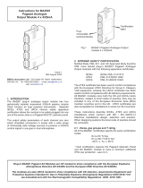
Step C and D
Remove the temporary
hole plug and install an
appropriate IP rated cable
gland or conduit fitting and
terminate field wiring.
Finally replace the terminal
cover and tighten the two
'A' screws.
Step B
Secure the instrument
to a flat surface with M6
screws through the
two 'B' holes.
Alternatively use a pipe
mounting kit.
Step A
Remove the terminal
cover by unscrewing
the two 'A' screws
B
D
DB
D
D
DISPLAY
DISPLAY
C
A
C
A
DISPLAY
PE
Fig 1 BA364E installation procedure
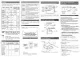
91
117
72
Two M6 clearance
holes for surface
mounting
M20 x 1.5 tapped. Supplied
with two IP66 stopping plugs
& one temporary hole plug.
1 2
RS1
RS2
3 4 5 6
C1 C2 C3 C4 A3 A4A1 A2
+
Alarm 1 Alarm 2
Terminals for
dual alarms
+
+
Terminals for
4/20mA output
ResetPower
supply
+
Add link
to energise
pulse input A
Pulse
input A
+
7 8 9 10
Add link
to energise
pulse input b
Pulse
input b
+
P1S2S1EP2
Pulse
output
Terminals S1 & S2
internally linked for
joining cable screens
+
141
212
Separate
terminal
compartment
DISPLAY
PE
Fig 2 Dimensions and terminal connections
EMC
For specied immunity all wiring should be in screened twisted
pairs with screens earthed at one point within the safe area.
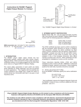
DISPLAY
PE
Safe area
Power
supply
Single channel
positive polarity
28V: 93mA
Zener barrier
Single channel
positive polarity
28V: 93mA
Zener barrier
Remote reset
in hazardous
area
Input b
Sensor
b
Input A
Remote reset
in safe area
6 5
+
4 3 10 9 8 7
RS2
RS1
2 1
+
+
Hazardous area
Sensor
A
+
Sensor output Input A Input b
Proximity detector
Switch contact
Open collector
Link
3 & 4
Link
7 & 8
Voltage pulse
Magnetic pick-off
Don’t link
3 & 4
Don’t link
7 & 8
Fig 3 Typical measurement loop
Units of measurement and tag number
The BA364E is tted with a blank escutcheon around the
liquid crystal display. This can be supplied printed with any
units of measurement and tag information specied at the
time of ordering. Alternatively, the information may be added
on-site via an embossed strip, dry transfer or a permanent
marker.
To gain access to the escutcheon remove the terminal cover by
unscrewing the two ‘A’ screws which will reveal two concealed
‘D’ screws. Remove the push buttons by unscrewing the
two ‘C’ screws and un-plug the ve way connector. Finally,
unscrew all four ‘D’ screws and carefully lift o the front of the
instrument. The location of all the screws is shown in Fig 1.
3. OPERATION
The BA364E is controlled and congured via four front panel
push buttons. In the display mode i.e. when the instrument
is counting the push button functions are:
) + & Grand total - shows the least signicant 8 digits of
a 16 digit counter.
) + * Grand total - shows the most signicant 8 digits of
a 16 digit counter. If buttons are pressed for longer
than 10 seconds the grand total will be reset to zero
if the grand total reset function clr gtot is enabled.
To reset the grand total to zero from the operating
mode press the ) and * buttons for ten seconds
until CLr. no is displayed. Using the & or * button
change the display to Clr . YE5 and press ) which will
reset the grand total and restore the original display.
& + * If the local total reset function clr tot is enabled in
the conguration menu, simultaneously pressing
the & and * buttons for more than three seconds
allows total A, total b or both totals to be selected
by operating the & or * button. Operating the
) button will then reset the selected total and
clear any stored output pulses.
( + & Shows in succession, rmware version number,
instrument function
2chcntr
and output
accessories which are always tted.
-A Control outputs
-P Pulse output
-c 4/20mA output
( + * Provides direct access to the alarm setpoints when
the AC5P setpoints function has been enabled.
( + ) Access to conguration menu
Abbreviated Instruction for
BA364E intrinsically safe two input
eld mounting Counter
Issue 3
24th November 2022
BEKA associates Ltd. Old Charlton Rd, Hitchin, Hertfordshire,
web: www.beka.co.uk
E
P


 1
1
 2
2


 BEKA associates BA367E User manual
 BEKA associates BA3501 Operating instructions
 BEKA associates BA304G-SS Installation guide
 BEKA associates BA3601 Owner's manual
KHADAS EDGE2 User guide
Omega Engineering DP-F30 User manual
 PRECISION DIGITAL PD8-6363 ProtEX-MAX User manual
Omega DPF-310 Series Owner's manual
 PRECISION DIGITAL PD6363 User manual
 PRECISION DIGITAL PD6363 User manual


