KC HiLiTES 97062 is a relay wire harness designed to power two lights with a maximum wattage of 130W each. It includes a switch, relay, sheet metal screw, and six wire ties for easy installation. The wire harness can be routed from the battery or other power source to the lights, and the switch can be mounted in a desired location. The relay should be mounted close to the battery with the blades facing down. The yellow power lead should be connected to the positive side of the battery, and the black ground lead should be connected to the negative side of the battery or chassis ground.
KC HiLiTES 97062 is a relay wire harness designed to power two lights with a maximum wattage of 130W each. It includes a switch, relay, sheet metal screw, and six wire ties for easy installation. The wire harness can be routed from the battery or other power source to the lights, and the switch can be mounted in a desired location. The relay should be mounted close to the battery with the blades facing down. The yellow power lead should be connected to the positive side of the battery, and the black ground lead should be connected to the negative side of the battery or chassis ground.

-
 1
1
KC HiLiTES 97062 Installation guide
- Type
- Installation guide
- This manual is also suitable for
KC HiLiTES 97062 is a relay wire harness designed to power two lights with a maximum wattage of 130W each. It includes a switch, relay, sheet metal screw, and six wire ties for easy installation. The wire harness can be routed from the battery or other power source to the lights, and the switch can be mounted in a desired location. The relay should be mounted close to the battery with the blades facing down. The yellow power lead should be connected to the positive side of the battery, and the black ground lead should be connected to the negative side of the battery or chassis ground.
Ask a question and I''ll find the answer in the document
Finding information in a document is now easier with AI
Related papers
-
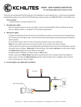 KC HiLiTES 519 Installation guide
-
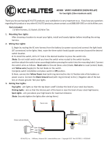 KC HiLiTES 6308 User manual
-
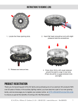 KC HiLiTES 4401 Installation guide
-
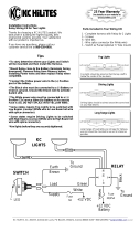 KC HiLiTES 9150 Installation guide
-
 KC HiLiTES 367 Installation guide
-
 KC HiLiTES 366 Installation guide
-
KC HiLiTES 91336 Operating instructions
-
KC HiLiTES KC 355 User manual
-
 KC HiLiTES 42341 User manual
-
KC HiLiTES M-RACK Installation guide
Other documents
-
ADVENTURE FURTHER 2-LIGHT 40A Relay 160W Wire Harness User manual
-
Western PRO‑PLOW Series 2, POLY PRO‑PLOW Series 2, PRO PLUS & MIDWEIGHT Mechanic's Guide
-
 Hiniker 700 User manual
-
Western HTS Mechanic's Guide
-
 Hiniker C-PLOW 8901 User manual
-
Western WIDE-OUT Mechanic's Guide
-
Western Prodigy Mechanic's Guide
-
Pentair Pool Products PG2000 840240 Installation guide
-
Western MVP PLUS Mechanic's Guide
-
 SnowDogg MD75 Owner's manual


